TDK-Lambda Genesys series Technical Manual
Lan interface
Hide thumbs
Also See for Genesys series:
- User manual (113 pages) ,
- Manual (44 pages) ,
- Instruction manual (28 pages)

Related Manuals for TDK-Lambda Genesys series


Summary of Contents for TDK-Lambda Genesys series
- Page 1 CONTROLLED COPY 19.01.09 N.L.I. R&D TECHNICAL MANUAL LAN INTERFACE GENESYS™ POWER SUPPLIES Document: IA672-04-01 Rev. D IA672-04-01-Rev. D...
- Page 2 This page is intentionally blank...
-
Page 3: Table Of Contents
Table of Contents GENERAL INFORMATION ................ 1 1.1. INTRODUCTION ....................1 1.2. FEATURE SUMMARY ...................2 1.3. GLOSSARY ....................3 1.4. REQUIRED ACCESSORIES .................4 SPECIFICATIONS ..................5 2.1. POWER SUPPLY SPECIFICATIONS ............5 2.2. LAN OPTION PHYSICAL DESCRIPTION .............5 2.3. LAN FEATURES ....................6 GETTING STARTED .................. 9 3.1. - Page 4 7.5. OUTPUT PROTECTION ................35 7.6. LAN SPECIFIC COMMANDS ..............36 7.7. COMMON COMMANDS ................38 7.8. ERROR AND STATUS COMMANDS ............39 7.9. RS-485 MULTI-DROP COMMANDS ............47 SAMPLE PROGRAMS ................49 RS-485 MULTI-DROP CHAIN ..............51 9.1. Introduction ....................51 9.2. Configure the LAN Supply ................51 9.3.
-
Page 5: General Information
1. GENERAL INFORMATION 1.1. INTRODUCTION The Local Area Network (LAN) option for the Genesys series power supply allows the user to remotely program, measure and check status of the power supply. It uses an Ethernet connection like those used to connect computers to each other and to the Internet A computer’s web page browser may be used to operate the power supply through a built-in web page server. -
Page 6: Feature Summary
1.2. FEATURE SUMMARY Communicate over any standard TCP/IP network • LAN (Local Area Network) WAN (Wide Area Network) Communicate across the world using the Internet Web page viewable with any web page browser, such as Internet Explorer • Optional password protection prevents unauthorized operation Program the output settings and protections Measure the power supply output, view the power supply status Configure the network connection settings... -
Page 7: Glossary
1.3. GLOSSARY 1.3.1. Auto-IP: This is when the power supply configures it’s own settings because they cannot be obtained using DHCP. When forced into an auto-IP situation, the power supply will select a random address in the range of 169.254.xxx.xxx 1.3.2. -
Page 8: Required Accessories
1.3.14. RS-485: A communication bus used by the Genesys™ power supply for a multi-drop system. One LAN supply controls a string of supplies that do not have the LAN option. This bus uses a 4-wire twisted pair cable through the J3-IN and J3-OUT connectors 1.3.15. -
Page 9: Specifications
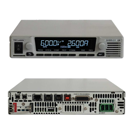
2. SPECIFICATIONS 2.1. POWER SUPPLY SPECIFICATIONS When using the LAN, the power supply ratings and accuracies are the same as for the digital remote programming using RS-232 or RS-485. See the Technical Manual for Genesys™ Power Supply for those specifications 2.2. -
Page 10: Lan Features
2.2.1. Link and Activity LED: this small LED, embedded in the RJ-45 socket, glows green when the connection is made to an active network and it blinks when any message packets are detected 2.2.2. Collision LED: this small LED, embedded in the RJ-45 socket, blinks amber when the LAN packets are corrupted by collisions 2.2.3. - Page 11 2.3.6. TCP/IP Protocols IPv4: conforms to Internet Protocol version 4 TCP: conforms to the Transmission Control Protocol for data packets over the network HTTP: the Hyper Text Transfer Protocol is a communication protocol that enables web page browsing over the network and the internet ICMP / Ping Server: Response to another device’s ping requests (unless disabled by the web page as described in section 5.5.4) 2.3.7.
- Page 12 This page is intentionally blank...
-
Page 13: Getting Started
3. GETTING STARTED 3.1. SELECT THE INTERFACE The power supply, with the LAN option installed, may be operated through three interfaces. This section describes how to enable each. Only one interface may be enabled at a time MODE NAME MODE DESCRIPTION Local Mode Control using the front panel encoders and buttons Control using the 3 or 4-wire serial digital J3-IN and... -
Page 14: Setup The Lan Computer
3.2. SETUP THE LAN COMPUTER 3.2.1. Using a Network Connection If the computer you are using is connected to a network server (as shown below), and the Genesys™ power supply is connected using routers, switches or hubs, then no further setup should be required for the computer Ethernet Computer with Web Page Viewer or... -
Page 15: Setup The Lan Power Supply
By default, the computer’s network interface card (NIC) will also be DHCP/auto-IP, so if no network server is detected, the computer will create it’s own valid IP address using the auto- IP feature If the computer and power supply both have auto-IP addresses, then the LAN connection may be made by simply typing the supply’s IP address into a web browser as described in section 3.4 3.3. -
Page 16: Ip Address Overview
Alternately, if the power supply is set for “DHCP/Auto-IP”, and if NetBIOS naming service is running on the computer, the hostname may then be used for addressing the web page as shown below. See Section 3.6 for a description of the hostname 3.5. -
Page 17: Troubleshooting The Web Connection
After a “LAN Reset” is done (see section 4.2), the power supply will create a default hostname based on the model and serial number of the supply The default hostname is in the format: < Product > < Voltage rating > – < Current rating > – < last 3 digits of serial number > If the rating has a decimal point, substitute “p”... -
Page 18: Other Troubleshooting
C. Try to “PING” the Supply The Ping utility verifies the computer can send a message and get a response from the power supply over the network On a Windows XP computer, open a command line window by: 1. Click the “Start” button, Select “Run…” 2. - Page 19 3.8.3. Cannot Open Web Page using Laptop or Dual-LAN Card Computer If you have a computer with two network cards, the computer may not know which card to use when trying to open the Genesys™ web page. Verify the two cards do not have over- lapping IP address ranges, otherwise it may be necessary to disable or disconnect the network card that is not being used If you have a laptop computer with an Ethernet jack and a wireless network, it may be...
-
Page 20: Connecting Over Wan
3.9. CONNECTING OVER WAN To connect over the a Wide Area Network (i.e.: the global internet ), the following settings must be made in the network server In the Genesys™ power supply LAN interface, there are two servers. One web server is listening in Port 80. -
Page 21: Lan Setup
4. LAN SETUP 4.1. VIEW THE IP AND MAC ADDRESSES When the power supply is running with the LAN enabled, the IP and MAC addresses may be viewed on the front panel by following these steps: Press and hold the FOLD button for three seconds. The 7-segment displays will show something such as: IP-1 By turning the voltage encoder knob, the complete IP and MAC addresses may be seen. - Page 22 IP address: 169.254.xxx.xxx (see section 3.2.2) • Subnet mask: 255.255.0.0 • Default gateway: 0.0.0.0 • DNS Server 0.0.0.0 • Hostname: GENvvv-aaa-sn (see hostname in section 5.2) • Description: “Genesys Power Supply” • Ping Server: Enable • Keep-Alive 1800 Seconds (30 minutes) before idle logged-in user •...
-
Page 23: Using The Web
5. USING THE WEB PAGES 5.1. OVERVIEW Once the web page is opened in a web browser program, most of the power supply’s settings may be viewed or changed from any location on the network 5.2. HOME PAGE The opening web page displays the model identity and LAN settings. Some of the fields are: VISA Name Using IP Address: For automation programming, VISA is a type of communication driver. -
Page 24: Logging In
Auto-Negotiate: This is a setting which allows the LAN port to adjust it’s speed to the fastest available on the network 5.3. LOGGING IN To change power supply output settings or to change the LAN settings, a user must first log in. By clicking the “Login”... -
Page 25: Dc Power Page
5.4. DC POWER PAGE When the “DC Power” tab is clicked, the following web page opens. This page, and it’s sub-menus, allow you to operate the power supply and adjust it’s output settings 5.4.1. DC Power ‡ Output Page When the “DC Power” tab is selected, four buttons are available across the top of the panel. Click the “Output”... - Page 26 button on the power supply front panel Measurements: This section displays the selected power supply’s actual output voltage and current and the operating mode (constant-voltage or constant-current or off). Also, faults are shown in the voltage display Settings: This section displays the selected power supply’s voltage and current limit settings (as if they were set on the front panel encoders) Modify Settings: This button is disabled (gray text) until you login (see section 5.3).
-
Page 27: Lan Page
(this resets any supplies connected to the multi-drop bus) C. Save (see section 7.7.3) (this saves the settings for only the supply selected in the RS-485 listbox) D. Recall (see section 7.7.4) (this recalls the settings for only the supply selected in the RS-485 listbox) 5.4.5. - Page 28 The following settings are shown on the “LAN ‡ Configure” web page: IP Address Source: Displays the way the IP address was selected. Options are DHCP/ Auto-IP and Static IP IP Address: Displays the IP address assigned to the power supply through either DHCP, Auto-IP or Static IP sources Subnet Mask: Displays the subnet mask assigned to the power supply through either DHCP, Auto-IP or Static IP (see glossary 1.3.16)
- Page 29 TCP/IP Mode: This selects how the power supply gets it’s network settings. Select either: DHCP Assigned / AUTO IP: If this mode is selected, the network server uses DHCP − to assign the IP address, subnet mask , default gateway and DNS server (see glossary section 1.3).
- Page 30 LAN Keep-Alive: If you are logged in as an administrator, this is how many seconds the web pages may be unused (idle) before the power supply automatically logs you out. The default is 1800 seconds = 30 minutes. Any mouse click on any page will reset the timer Ping Server: ‘Ping’...
- Page 31 5.5.5. LAN ‡ Users Page This page allows you to create password protection for the web pages. There is no password protection for automation programming with VISA (see sections 6 and 7) By default, the “old password” is blank. The new password must be four or more characters long Reset the password: once a password is applied, it may be changed by using this screen, but it can only be removed by performing the “LAN Reset”...
-
Page 32: Help Page
5.6. HELP PAGE The left side of the power supply’s web page has a Help tab. When clicked, the following page appears: This page is a set of Internet links to Lambda website pages. Your network administrator must assign the power supply’s default gateway (see section 5.5.2) and give privileges to view and download from the internet... -
Page 33: Remote Programming Using Commands
6. REMOTE PROGRAMMING USING COMMANDS 6.1. OVERVIEW How to communicate with test and automation systems, called the programmatic interface, is described in this section This method uses a computer’s LAN connection to send text commands to the power supply, and to read text responses back. The format of the text messages is called SCPI. A driver layer between the user’s program and the LAN protocol is called VISA. -
Page 34: Socket Programming
6.5. SOCKET PROGRAMMING In addition to web page and VISA communication, programs may be written which communicate through raw sockets. Use port 8001 to write and read SCPI commands... -
Page 35: Scpi Command Reference
7. SCPI COMMAND REFERENCE 7.1. COMMAND SYNTAX 7.1.1. General SCPI Rules Terminator: no terminator is required, but carriage-returns or line feeds at the end of the SCPI message is allowed Characters: commands are made of printable letters, numbers, spaces and some punctuations. -
Page 36: Configuring The Output
For a command is described as: |MAX > [SOURce]:VOLTage:PROTection:LEVel <nn.nn The following are correct forms of the same command: (longest form of command) SOURCE:VOLTAGE:PROTECTION:LEVEL MAX (SOURCE is optional) :VOLTAGE:PROTECTION:LEVEL (Abbreviate VOLTAGE) :VOLT:PROTECTION:LEVEL MAX (Shortest form of command) :VOLT:PROT:LEV MAX (Small letters acceptable) :volt:prot:lev max The following are invalid forms of the command and will cause an error: (missing parameter, MAX or number) -
Page 37: Measuring The Output
including AC fault, over-temperature, J1-Enable and J1-Shut Off, will prevent turning the output on until the fault clears. For non-latching faults, including over-voltage and current fold-back, turning the output on will clear the fault Syntax: OUTPut:STATe <0|1|OFF|ON> Parameter: 0 or OFF will set the power supply output to OFF 1 or ON will set the power supply output to ON, if it is able to Example:... - Page 38 the power supply outputs and statuses. However, as soon as one LAN command is used to change the supply output, the supply will automatically go into remote mode See section 3.1.1 for further discussion of the local and remote modes Syntax: SYSTem:SET <0|1|2|LOC|REM|LLO>...
-
Page 39: Output Protection
7.5. OUTPUT PROTECTION 7.5.1. Set Over-Voltage Protection This command sets the over-voltage protection level. If the power supply output exceeds this voltage at it’s output (or remote sense point), then the output will immediately turn off, the supply front panel will show “OUP” and the Questionable Condition register bit 4 will be set high. -
Page 40: Lan Specific Commands
Errors: SYSTEM:ERROR? may return errors including: +302,”PV below UVL” +306,”UVL above PV” -222,”Data out of range” 7.5.4. Set Foldback Protection This command enables or disables the foldback protection. When the FB protection is enabled, if the power supply goes into constant-current (CC) mode for about a ½ second, then the output will turn off, the front panel will show “Fb”... - Page 41 7.6.2. Read the Hostname The hostname (see section 1.3.6) may be read with this query Syntax: SYSTem:COMMunicate:LAN:HOST? Example: SYST:COMM:LAN:HOST? Response: The hostname string, up to 15 characters long Example: GEN7p5-1000-123 is a typical default hostname 7.6.3. Read the IP Address The IP address (see section 1.3.9) may be read with this query Syntax: SYSTem:COMMunicate:LAN:IP?
-
Page 42: Common Commands
Refer to the Genesys Technical Manual for a description of the RS-232 & RS-485 Remote Control command set Syntax: DIAGnostic:COMMunicate:PASSthrough <string> Parameter: <string> is any RS-232/485 command or query (no quotes are used to enclose the string) Example #1: will program the voltage limit to 25 volts DIAG:COMM:PASS PV 25 Response #1: OK will be returned by the above command,... -
Page 43: Error And Status Commands
7.7.3. Save All Settings This saves the present power supply settings. This is used along with the *RCL 0 command (in section 7.7.4) which allows you to bring the power supply back to some setup configuration with only one command When the supply is powered-down, the *SAV 0 settings are over-written by the power- down settings Syntax:... - Page 44 7.8.1. Read System Error This is query to read error messages from the power supply. It is recommended that after any command is sent over the LAN, the SYSTEM:ERROR should be read to verify the command is accepted. The SYSTEM:ERROR queue can also be set to report faults which have shut-down the supply’s output The SYSTEM:ERROR is a queue, or stack, that holds the last ten messages.
- Page 45 7.8.3. Read SCPI Version This query returns the SCPI version that the Genesys™ power supply is compatible with Syntax: SYSTem:VERSion? Example: SYST:VERS? Response: <SCPI version> Example: 1999.0 USING THE ERROR AND STATUS REGISTERS The SCPI error and status registers report many conditions, statuses and events into short numeric codes.
-
Page 46: Figure 6. Error And Status Registers
THE IEEE-488.2 ERROR AND STATUS REGISTERS Questionable Condition Syst:Err Queue Condition Enable Event LSB 0 ISUM (for Multidrop) ISUM ISUM AC Fail Over Temperature Fold Back Prot Over Voltage Prot Shut Off Output Off Output Enable Internal Input Overflow INPO INPO Internal Overflow INTO... - Page 47 7.8.5. Read the Status Byte Register The Status Byte register is a summary of all events that have been enabled. Figure 6 shows the commands that are used to enable events. The Status Byte is a condition register, that is, reading it will not clear the contents. To clear the Status Byte register, the connected event registers must be read or cleared These are the bit assignments of the Status Byte: VALUE...
- Page 48 Syntax: *ESR? Response: <nnn>, a number from 0 to 255 Example: 32 (an illegal command was received) 7.8.8. Set the Standard Event Status Enable Register When one or more bits in the Standard Event Status Event Register (*ESR, see above) are set, a bit can be set in the Status Byte (*STB,see section 7.8.5).
- Page 49 Syntax: STATus:OPERation:CONDition? Example: STAT:OPER:COND? Response: <nnn>, a number from 0 to 255 Example: 128 (local mode with the output off (because CV and CC both zero)) 7.8.12. Set the Operational Condition Enable Register When one or more bits in the Operational Condition Condition Register (see 7.8.11 above) are set, a bit can be set in the Status Byte (*STB,see section 7.8.5).
- Page 50 These are the bit assignments of the Questionable Condition Condition Register: VALUE SYMBOL DESCRIPTION 0 or In single LAN supply, bit is always 0. ISUM In Multi-drop system, is Instrument Summary bit. AC Fail fault Over-temperature fault Fold-back protection fault Over-voltage protection fault Shut-off fault, using the “J1”...
-
Page 51: Rs-485 Multi-Drop Commands
Response: <nnn>, a number from 0 to 4095 Example: 12 (the supply went into fold-back fault then the AC voltage dropped) 7.8.17. Enable All the Event Registers This command that will enable some of the events for the operational (section 7.8.12) and all of the events for the questionable (section 7.8.15) registers. - Page 52 This page is intentionally blank...
-
Page 53: Sample Programs
8. SAMPLE PROGRAMS Refer to Lambda website for the latest support software at: http://www.lambdaeurope.com http://www.lambdaeurope.com/uk/mand_pages/drivers_download.htm Downloads may include: GUI program • This is a “Graphical User Interface” program that gives you remote control of the power supply using the LAN network IVI-COM Drivers •... - Page 54 This page is intentionally blank...
-
Page 55: Rs-485 Multi-Drop Chain
9. RS-485 MULTI-DROP CHAIN 9.1. Introduction The Genesys™ power supply LAN option allows you to control up to 29 other supplies which do not have the LAN option installed. All are controlled through one IP address from the supply with the LAN option This is called the Multi-drop configuration. -
Page 56: Connect And Configure The Rs-485 Supplies
9.2.2. To Set the RS-485 Address: In addition to the supply’s IP address, the multi-drop requires setting an RS-485 address. It is viewed on the front panel of the power supply by setting it to local mode (see section 3.1.1) and pressing and holding the REM/LOC button. The address may then be changed by turning the voltage encoder The default RS-485 address is 6. -
Page 57: Multi-Drop Programming Using Scpi Commands
9.4. Multi-drop Programming Using SCPI Commands 9.4.1. Selecting One Power Supply in a Multi-drop Chain All the SCPI commands in section 7 may be sent to any one of the supplies in an RS-485 chain by first sending the INST:SEL address command. All commands and queries will then apply only to the selected supply, until a new INST:SEL is sent When a multi-drop chain is first powered-up, the LAN supply is automatically the one selected until the first INST:SEL is sent... - Page 58 GLOBAL COMMANDS The following global commands affect all power supplies on a multi-drop chain. See section 9.4.2 for requirements. There is no query version of these commands 9.4.4. Global Set the Voltage Limit This is the global version of the :VOLT command in section 7.2.1 Syntax: GLOBal:VOLTage[:LEVel][:IMMediate][:AMPLitude] <nn.nn>...
- Page 59 A structural register difference is, in all the RS-485 chained supplies, the Operational Condition Event Register and the Questionable Condition Event Register are ORed together to generate an event in the LAN supply’s Questionable Condition Event Register bit 0. This is called the ISUM bit and it may be used to set a bit in the Status Byte if an event occurs in the LAN or any RS-485 supply Other differences are:...
- Page 60 This page is intentionally blank...
-
Page 61: System:error? Messages
10. SYSTEM:ERROR? MESSAGES These are the system error messages which may be returned from the “SYST:ERR?” query. See section 7.8.1 for a description of this system error queue ERROR ERROR MESSAGE ERROR DESCRIPTION “No error” No error reported -100 “Command error” LAN card receives command with unspecified error A character was received that is not: -101... - Page 62 +340 “Internal message fault” General non-specified Internal message fault +341 “Input overflow” LAN card input data buffer is too full. Serial receive buffer in LAN card is full because the Main +342 “Internal overflow” micro sent too many characters LAN card did not receive response from supply before +343 “Internal timeout”...
-
Page 63: Customer Support
11. CUSTOMER SUPPORT For further assistance regarding the LAN interface, please contact the factory or a local service center in your area. To get a list of service centers in your country, go to: http://www.lambdaeurope.com... - Page 64 NOTES...
Need help?
Do you have a question about the Genesys series and is the answer not in the manual?
Questions and answers