TDK-Lambda GENESYS Series Instruction Manual
Programmable dc power supplies, g1.7 - 5kw in 1u 0-600v, 0-500a, parallel kit
Hide thumbs
Also See for GENESYS Series:
- User manual (113 pages) ,
- Technical manual (64 pages) ,
- Manual (44 pages)

Related Manuals for TDK-Lambda GENESYS Series


Summary of Contents for TDK-Lambda GENESYS Series
- Page 1 Series Programmable DC Power Supplies G1.7 - 5kW in 1U 0-600V, 0-500A PARALLEL KIT INSTRUCTION MANUAL The manual covers kit options: G/P-3U-10V G/P-3U-20-40V G/P-3U-60-100V G/P-3U-150-600V ...
- Page 2 General Parallel kit is supplied separately from the power supply packing according to order. The usage of parallel kit is according to customer's needs. Advanced Parallel For parallel connection, refer to advanced parallel chapter in the series User Manual. Product Safety Instructions Safety approvals are valid for single unit only.
- Page 3 Image Component Quantity M3 x 4C Flat Head Screw, Nickel Plated 8 Paralleling Cable 2 Output Cover 1 Bus Bar Insulator 2 M3 x 8 SEMS Screw, Nickel Plated 6 3 ...
- Page 4 1.4.1.2 Installation Steps 1. Attach connection plates, one on each side of the power supplies, using 12 pan head screws, 12 helical spring-lock washers and 12 plain washers as illustrated in Figure 1. Connection Plate 3U Plain Washer, No. 10, Stainless Steel Helical Spring‐Lock Washer, No. 10, Stainless Steel ...
- Page 5 3. Connect two paralleling cables from top unit M connector to bottom unit S connector as illustrated in Figure 3. Paralleling Cable Figure 3: Three 10V Units Paralleling Cable Connection 4. Insert output cover through the cables as illustrated in Figure 4. ...
- Page 6 5. Assemble two lugs on each bus bar, one on each side, using two hexagon bolts, four plain washers, two helical spring-lock washers and two hexagon nuts as illustrated in Figure 5. Hexagon Nut, M10, Stainless Steel Helical Spring‐Lock Washer, M10, Stainless Steel Plain Washer, M10, Stainless Steel M10 x 25 Hexagon Bolt, Stainless Steel ...
- Page 7 7. Fix output cover to the power supplies using six SEMS screws as illustrated in Figure 7. M3 x 8 SEMS Screw, Nickel Plated Tightening torque: 4.7‐5.7 Lbf‐inch (0.53‐0.64Nm) Figure 7: Three 10V Units Output Cover Assembly ...
- Page 8 1.4.2 G/P-3U-20-40V - Assembly Instructions for three 20V-40V units in Parallel 1.4.2.1 Components List Image Component Quantity 10‐32 x 5/16 Pan Head Screw, Stainless Steel 12 Helical Spring‐Lock Washer, No. 10, Stainless Steel 12 Plain Washer, No. 10, Stainless Steel 12 Connection Plate 3U 2 Output Short 2 M3 x 4C Flat Head Screw, Nickel Plated 8 Paralleling Cable 2 ...
- Page 9 Image Component Quantity Bus Bar Insulator 2 Protection Insulator 1 M3 x 8 SEMS Screw, Nickel Plated 8 9 ...
- Page 10 1.4.2.2 Installation Steps 1. Attach connection plates, one on each side of the power supplies, using 12 pan head screws, 12 helical spring-lock washers and 12 plain washers as illustrated in Figure 8. Connection Plate 3U Plain Washer, No. 10, Stainless Steel Helical Spring‐Lock Washer, No. 10, Stainless Steel ...
- Page 11 3. Connect two paralleling cables from top unit M connector to bottom unit S connector as illustrated in Figure 10. Paralleling Cable Figure 10: Three 20V‐40V Units Paralleling Cable Connection 4. Insert output cover through the cables as illustrated in Figure 11. ...
- Page 12 5. Assemble one lug on each bus bar using two hexagon bolts, four plain washers, two helical spring-lock washers and two hexagon nuts as illustrated in Figure 12. Hexagon Nut, M10, Stainless Steel Helical Spring‐Lock Washer, M10, Stainless Steel Plain Washer, M10, Stainless Steel M10 x 25 Hexagon Bolt, Stainless Steel Tightening torque: 220‐265 Lbf‐inch (24.9‐29.9 Nm) ...
- Page 13 7. Fix output cover to the power supplies using six SEMS screws as illustrated in Figure 14. M3 x 8 SEMS Screw, Nickel Plated Tightening torque: 4.7‐5.7 Lbf‐inch (0.53‐0.64Nm) ...
- Page 14 1.4.3 G/P-3U-60-100V - Assembly Instructions for three 60V-100V units in Parallel 1.4.3.1 Components List Image Component Quantity 10‐32 x 5/16 Pan Head Screw, Stainless Steel 12 Helical Spring‐Lock Washer, No. 10, Stainless Steel 12 Plain Washer, No. 10, Stainless Steel 12 Connection Plate 3U 2 Output Short 2 M3 x 4C Flat Head Screw, Nickel Plated 6 Paralleling Cable 2 ...
- Page 15 Image Component Quantity Bus Bar Protection Bracket 1 Bus Bar Cover Plug 6 M3 x 8 SEMS Screw, Nickel Plated 8 15 ...
- Page 16 1.4.3.2 Installation Steps 1. Attach connection plates, one on each side of the power supplies, using 12 pan head screws, 12 helical spring-lock washers and 12 plain washers as illustrated in Figure 16. Connection Plate 3U Helical Spring‐Lock Washer, No. 10, Stainless Steel Plain Washer, No. 10, Stainless Steel 10‐32 x 5/16 Pan Head Screw, Stainless Steel ...
- Page 17 3. Connect two paralleling cables from top unit M connector to bottom unit S connector as illustrated in Figure 18. Paralleling Cable Figure 18: Three 60V‐100V Units Paralleling Cable Connection 4. For load wires with a diameter smaller than or equal to 11 millimeter insert six bus bar cover plugs into the bus bar protection bracket and fix it to the output cover using two SEMS screw.
- Page 18 5. For load wires with a diameter greater than 11 millimeter divide each bus bar cover plug into two separate parts by bending and breaking it along its separate grooves, as illustrated in Figure 20. Insert only the rounded parts into the bus bar protection bracket and fix it to the output cover using two SEMS screw.
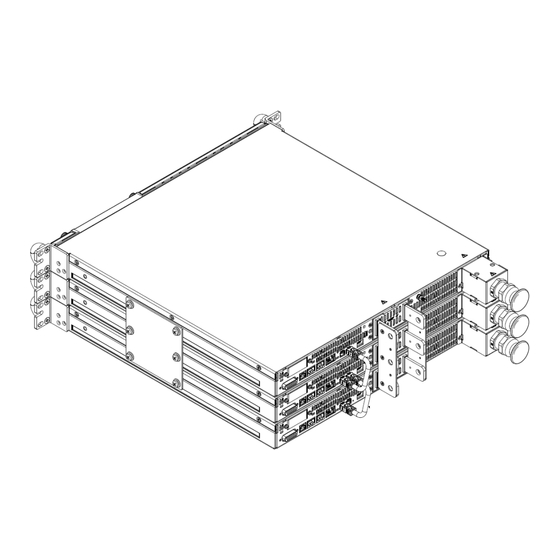
- Page 19 7. Fix output cover to the power supplies using six SEMS screws as illustrated in Figure 22. M3 x 8 SEMS Screw, Nickel Plated Tightening torque: 4.7‐5.7 Lbf‐inch (0.53‐0.64Nm) Figure 22: Three 60V‐100V Units Output Cover Assembly 1.4.4 G/P-3U-150-600V - Assembly Instructions for three 150V-600V units in Parallel 1.4.4.1 Components List Image Component ...
- Page 20 Image Component Quantity Paralleling Cable 2 Fixing Bracket 1 M3 x 8 SEMS Screw, Nickel Plated 6 Output Bracket G+15KW 1 M3 x 10 SEMS Screw, Nickel Plated 4 Output Bracket 1 M3 x 6G Flat Head Screw, Nickel Plated 2 Output Plug 1 20 ...
- Page 21 1.4.4.2 Installation Steps 1. Attach connection plates, one on each side of the power supplies, using 12 pan head screws, 12 helical spring-lock washers and 12 plain washers as illustrated in Figure 23. Connection Plate 2U Plain Washer, No. 10, Stainless Steel Helical Spring‐Lock Washer, No. 10, Stainless Steel ...
- Page 22 3. Attach fixing bracket to power supply’s back side using six SEMS screws, eight millimeter screw length, as illustrated in Figure 25. Make sure the horizontal tab is located as illustrated in Figure 25. Horizontal Tab M3 x 8 SEMS Screw, Nickel Plated Tightening torque: 4.7‐5.7 Lbf‐inch (0.53‐0.64Nm) Figure 25: Fixing bracket installation ...
- Page 23 5. Attach output bracket G+15KW to fixing bracket using four SEMS screws, ten millimeter screw length, screws as illustrated in Figure 27. M3 x 10 SEMS Screw, Nickel Plated Tightening torque: 4.7‐5.7 Lbf‐inch (0.53‐0.64Nm) Figure 27: Output bracket G+15KW installation ...
- Page 24 6. Attach output bracket to output bracket G+15KW using two flat head screws as illustrated in Figure 28. M3 x 6G Flat Head Screw, Nickel Plated Tightening torque: 4.7‐5.7 Lbf‐inch (0.53‐0.64Nm) Figure 28: Output bracket installation 7. Connect two paralleling cables from top unit M connector to bottom unit S connector as illustrated in Figure 29.
- Page 25 8. To operate the power supply use the output plug and fasten it using its two built-in screws as illustrated in Figure 30. Built‐in screws Output plug Tightening torque: 3.8 Lbf‐inch (0.43Nm) Figure 30: Output plug 25 ...
- Page 26 This page intentionally left blank 26 ...
- Page 27 NOTES _________________________________________________ _________________________________________________ _________________________________________________ _________________________________________________ _________________________________________________ _________________________________________________ _________________________________________________ _________________________________________________ _________________________________________________ _________________________________________________ _________________________________________________ _________________________________________________ _________________________________________________ _________________________________________________ _________________________________________________ _________________________________________________ _________________________________________________ _________________________________________________ _________________________________________________ _________________________________________________ _________________________________________________ _________________________________________________ _________________________________________________ _________________________________________________ _________________________________________________ _________________________________________________ _________________________________________________ _________________________________________________ ...
- Page 28 NOTES _________________________________________________ _________________________________________________ _________________________________________________ _________________________________________________ _________________________________________________ _________________________________________________ _________________________________________________ _________________________________________________ _________________________________________________ _________________________________________________ _________________________________________________ _________________________________________________ _________________________________________________ _________________________________________________ _________________________________________________ _________________________________________________ _________________________________________________ _________________________________________________ _________________________________________________ _________________________________________________ _________________________________________________ _________________________________________________ _________________________________________________ _________________________________________________ _________________________________________________ _________________________________________________ _________________________________________________ _________________________________________________ ...
Need help?
Do you have a question about the GENESYS Series and is the answer not in the manual?
Questions and answers