Table of Contents
Advertisement
Quick Links
Advertisement
Table of Contents

Subscribe to Our Youtube Channel
Summary of Contents for WALLACH FETAL2EMR 902300
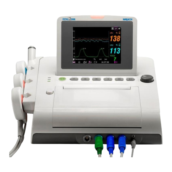
- Page 1 Fetal Monitor REF 902300 37474 • Rev B • 2/12...
- Page 3 No part of this document may be photocopied, reproduced or translated to another language without prior written consent of Wallach. All information contained in this publication is believed to be correct. Wallach shall not be liable for errors contained herein nor for incidental or consequential damages in connection with the furnishing, performance, or use of this material.
-
Page 4: Table Of Contents
Table of Contents Chapter 1 Safety Guide ......................... 1 1.1 Intended Use........................1 1.2 Instruction for Safe Operation ..................... 1 1.3 Ultrasound Safety Guide ..................... 2 1.4 Safety Precautions ....................... 2 1.5 Definitions and Symbols ..................... 6 Chapter 2 Monitor and Accessories ....................8 2.1 Opening and Checking Package .................. - Page 5 5.2.2 Choosing Paper Speed .................... 31 5.2.3 Changing Print Timer ....................31 5.2.4 Switching Print Self-Check On or Off ..............32 5.3 Understanding Recorder Paper Printout................32 Chapter 6 Pre-Monitoring Preparation ..................34 6.1 Confirming Fetal Life ....................... 34 6.2 Switching On ........................34 6.3 Checking Recorder Paper ....................
- Page 6 9.2 Completing the Monitoring ....................54 9.3 Switching Off ........................54 Chapter 10 Maintenance and Cleaning ..................55 10.1 Maintenance ........................55 10.1.1 Maintaining Inspection..................55 10.1.2 Maintenance of Monitor ..................55 10.1.3 Maintenance of Transducers ................. 56 10.1.4 Storage of Recorder Paper ..................56 10.1.5 Maintenance of Recorder ..................
-
Page 7: Chapter 1 Safety Guide
Wallach Fetal2EMR Fetal Monitor. 1.1 Intended Use The Wallach Fetal2EMR (Model F3) Fetal Monitor (hereinafter called Fetal2EMR) is intended for non-invasive monitoring of a single or twin fetuses during antepartum examination, labor and delivery. It is intended to be used only by trained and qualified personnel in antepartum examination rooms, labor and delivery rooms. -
Page 8: Ultrasound Safety Guide
Chapter 1: Safety Guide 1) Ultrasound (FHR1, FHR2) 2) External TOCO 3) Intrauterine Pressure (IUP) 4) Fetal Movement Mark (FM) This symbol indicates that the electric shock defend grade of this applied part is Type BF. DECG (Direct Electrocardiography) (Not available in this model) This symbol indicates that the protection against electric shock of this applied part is Type CF. - Page 9 15 The monitor is not protected against defibrillation. Do not apply it during electrosurgery or MRI; as it might result in harm to the patient or the operator. 16 Only connect accessories supplied or recommended by Wallach Surgical Devices to the device.
- Page 10 Chapter 1: Safety Guide technical service department or your local distributor. Proper Monitoring Safety Precautions: Clinical decision making based on the output of the device is left to the discretion of the provider. Alarms may be set up based on different situations. Audio should be activated when monitor is in use.
- Page 11 Replace the battery with a new one the same as the one provided or recommended by Wallach Surgical Devices. 16 When not using battery for an extended period, remove it from the monitor and store it in a place with low humidity and low temperature.
-
Page 12: Definitions And Symbols
Chapter 1: Safety Guide 1.5 Definitions and Symbols Socket for ultrasound transducer 1 (Type BF applied part) Socket for ultrasound transducer 2 (Type BF applied part) Socket for DECG cable ( Type CF applied part) Socket for TOCO transducer or IUP cable (Type BF applied part) Socket for Remote Event Marker (Type BF applied part) Reserved Type BF applied part... - Page 13 Chapter 1: Safety Guide Channel selection Equipotential Grounding System Fuse Attention See Instructions for use Antenna USB (Universal Serial Bus) Connection Serial interface Network port The symbol indicates that the device complies with the European Council Directive 93/42/EEC concerning medical devices. The symbol indicates that the device should be sent to the special agencies according to local regulations for separate collection after its useful life.
-
Page 14: Chapter 2 Monitor And Accessories
Chapter 2: Monitor and Accessories Chapter 2 Monitor and Accessories 2.1 Opening and Checking Package Visually examine the package prior to unpacking. If any signs of mishandling or damage are detected, contact the carrier and file a claim for damage. Open the package and take out the monitor and accessories carefully. -
Page 15: Overview
Chapter 2: Monitor and Accessories 2.2 Overview 1 Alarm Indicator 2 LCD 3 Keys 4 Control Knob 5 Paper Drawer 6 Accessory Ports 7 Indicators 8 Paper Drawer Latch Figure 2-1 Front View 9 Accessory Holder Figure 2-2 Left Panel - 9 -... - Page 16 Chapter 2: Monitor and Accessories 10 DECG Socket 11 TOCO/IUP Socket 12 FHR1 Socket 13 FHR2 Socket 14 MARK Socket 15 EXT.1 Socket 10 11 12 13 14 15 Figure 2-3 Front Panel 16 Power Socket 17 Equipotential Grounding Terminal 18 DB9 Socket 19 RJ45Socket 20 USB Socket...
-
Page 17: Keys And Control Knob
Chapter 2: Monitor and Accessories 21 Handle 22 Battery Compartment Figure 2-5 Bottom Panel 2.2.1 Keys and Control Knob Figure 2-6 Keys and Control Knob The Fetal2EMR monitor is a user-friendly device with operation controlled by a few keys on the front panel and the control knob. - Page 18 Chapter 2: Monitor and Accessories (3) SILENCE key Function: Switch on/off the alarm sound Press this key to switch on/off the alarm sound. (4) AUTO ZERO key Function: TOCO zero Adjust the external TOCO contractions trace/value to preset unit (external monitoring contractions) or the IUP trace/value to reference point 0 (internal monitoring contractions).
-
Page 19: Indicators
Chapter 2: Monitor and Accessories a) A menu pops up on the screen, or the menu is replaced by another one. b) A submenu with several options appears. If this item has more than 6 options, they will be displayed on more than one page. Select Prev to switch to the previous page, or select Next to switch to the next page. -
Page 20: Accessories
Chapter 2: Monitor and Accessories 2.3 Accessories 2.3.1 Ultrasound (US) Transducer 1 US Transducer (Pink Labeled) 2 Transducer Cable 3 Transducer Connector Figure 2-7 US Transducer 2.3.2 TOCO Transducer 1 TOCOS Transducer (Blue Labeled) 2 Transducer Cable 3 Transducer Connector Figure 2-8 TOCO Transducer 2.3.3 Belt Figure 2-9 Belt... -
Page 21: Remote Event Marker
Chapter 2: Monitor and Accessories 2.3.4 Remote Event Marker 1 Marker Plug 2 Press Key Figure 2-10 Remote Event Marker 2.4 Screen 2.4.1 Main Interface 17 16 13 12 11 Figure 2-11 Main Interface Item Screen element Description Alarm messages displaying area Alarm reviewing key - 15 -... - Page 22 Chapter 2: Monitor and Accessories Display mode switch Setup key Fetal heart sound volume adjust/indicator: : the current fetal heart sound comes from this channel. : the fetal heart sound of this channel is mute. Fetal heart signal quality indicator: poor acceptable optimum...
-
Page 23: Setup Interface
Chapter 2: Monitor and Accessories 2.4.2 Setup Interface The setup menu is provided to change the monitor configurations and monitoring settings. Press the Setup key on the main interface to open this menu. Figure 2-12 Setup Menu Item Screen element Setup Items Function Description In the setup main menu, you have access to all the items other than System. -
Page 24: Chapter 3 Installation Guide
Chapter 3: Installation Guide Chapter 3 Installation Guide Note: Installation must be carried out by qualified personnel authorized by Wallach Surgical Devices. In order to ensure the operator and patient safety, read through this chapter before using this monitor. 3.1 Installing Battery WARNING Switch off the monitor and unplug it before installing or removing the battery. - Page 25 Chapter 3: Installation Guide Battery Connector Anode & Cathode of Battery Output WARNING Do not touch the anode and cathode of the battery output with fingers or metal materials, to avoid hazards caused by the short-circuit. 4) Arrange the battery flat in the compartment, and push the strip at the end of the battery into the gap.
-
Page 26: Installing Monitor
Chapter 3: Installation Guide 2 When the battery configuration is provided, after the device is transported or stored, the battery must be charged. Connecting the Fetal2EMR to a power supply will charge the battery even if the monitor is not turned on. 3.2 Installing Monitor The monitor should be placed on a flat surface. - Page 27 Chapter 3: Installation Guide 2) Take out the thermosensitive paper; remove the wrapper. 3) Guide the pack into the drawer underneath the retaining rod, abutting it against the right edge. Make sure the blank side of the paper faces you and the FHR trace area is on the left. 4) Unfold a sheet from the top of the pack and pull its end out of the drawer (make sure the pack in the drawer remains flat).
- Page 28 2 Make sure the paper pack in the drawer remains flat when the top sheets are pulled out of the drawer. If paper deflection is detected after the drawer cover is closed, reload paper to prevent paper jam. Use only paper provided by Wallach Surgical Devices to avoid printing problems.
-
Page 29: Tearing Off Recorder Paper
Chapter 3: Installation Guide 3.4 Tearing Off Recorder paper Perform the following procedure to tear off the recorder paper: 1) Press the PRINT key on the front panel if the recorder is running. 2) Pull up the end of the paper (fold the paper if it is very long), and use moderate force to tear paper off in an upward motion along the paper-cutting edge. -
Page 30: Connecting Transducers
Chapter 3: Installation Guide 3.6 Connecting Transducers Check for visible damage to the transducers every time before connecting them to the monitor. Pay special attention to possible cracks on the transducers and cables before immersing them into conductive fluid. If damage is found, replace them. When plugging transducers into the monitor, make sure the arrow symbol of the connector is facing up. -
Page 31: Connecting Power Cable
Chapter 3: Installation Guide all the way into one of the holes on the holder. Make sure that the transducer cable is on the bottom. To place the remote event marker, put the small end of the marker into the hole as far as it can go. Placing the transducer Placing the marker NOTE:... -
Page 32: Chapter 4 Alarms
Chapter 4: Alarms Chapter 4 Alarms 4.1 Alarms Classification The monitor has two types of alarm: patient alarm and technical alarm. Patient alarms indicate that the vital signs are exceeding its configured limit. They can be disabled. The adjustable alarm limits determine the conditions that trigger the alarm. Technical alarms indicate that the monitor cannot measure and therefore cannot reliably detect critical patient conditions. -
Page 33: Visual Alarm
Chapter 4: Alarms 4.3 Visual Alarm When an alarm is active, the following 3 visuals occur: Alarm indicator: the alarm indicator lights up. Alarm Category Indicator Color Flashing Frequency Duty Cycle Medium level alarm Flashing orange 0.4Hz to 0.8Hz 20% to 60% on Low level alarm orange... -
Page 34: Changing Alarm Volume
Chapter 4: Alarms 4.6 Changing Alarm Volume To change the alarm volume: 1 Select the setup key on the main interface. 2 Select Alarm > Alarm Volume. 3 Select Low (default), Medium or High. 4 Select OK. 4.7 Reviewing Alarms An alarm reviewing menu records a list of up to 50 of the most recent patient and technical alarm messages with date and time information. -
Page 35: Testing Alarms
Chapter 4: Alarms 4.9 Testing Alarms To test the functions of visible and audible alarms, do the following: 1. Switch on the monitor. 2. Enable the alarm. 3. Set the alarm limits to a narrow range. 4. Simulate a signal that is higher than the upper alarm limit or lower than the lower alarm limit. -
Page 36: Chapter 5 Printing
Chapter 5: Printing Chapter 5 Printing 5.1 Function Description The built-in thermal recorder applied in the monitor supports both the American and international standard width recorder paper. It prints continuous traces synchronously along with marks. The monitor supports some other functions listed below: ... -
Page 37: Switching Auto Start Printing On Or Off
Chapter 5: Printing 5.2.1 Switching Auto Start Printing On or Off Switch auto start printing on or off as follows: 1. Select the setup key on the main interface. 2. Select Start Monitoring > PRINT. 3. Select ON or OFF (default). 4. -
Page 38: Switching Print Self-Check On Or Off
Chapter 5: Printing 5.2.4 Switching Print Self-Check On or Off To switch print self-check on or off: 1. Select the setup key on the main interface. 2. Select Recorder > Print Self-Check. 3. Select ON or OFF (default). 4. Select OK. 5.3 Understanding Recorder Paper Printout WARNING 1 If there is any difference between the display and the printout, the printout should... - Page 39 Chapter 5: Printing Item Information Description Patient The patient’s ID and name. Information The monitor prints a self-check trace after being switched on. It is used to Self-Check Trace check if the recorder paper is properly loaded. The FHR pane range 30 bpm ~ 240 bpm indicates the paper style is Paper Style American Standard.
-
Page 40: Chapter 6 Pre-Monitoring Preparation
If any sign of damage is detected, or the monitor displays some error messages, do not use it on a patient. Contact biomedical engineer in the hospital or the Wallach service engineer immediately. -
Page 41: Checking Recorder Paper
Chapter 6: Pre-Monitoring Preparation 6.3 Checking Recorder Paper The monitor provides the print self-check function to check if the recorder paper is loaded correctly and set. The recorder prints a baseline after start-up (if Print Self-Check in the menu is ON). Observe the borders of the printed baselines (illustrated with the arrow). -
Page 42: Adjusting Volume
Chapter 6: Pre-Monitoring Preparation 6.5 Adjusting Volume The monitor automatically detects which channel the ultrasound transducer is connected to. The corresponding volume adjustment key of this channel displays , indicating the fetal heart sound is coming out from this channel; while the other one displays , for example: Press the CHANNEL key to switch the fetal heart sound to the other channel. -
Page 43: Chapter 7 Fetal Monitoring
Chapter 7: Fetal Monitoring Chapter 7 Fetal Monitoring WARNING The monitor is not intended for use in intensive care units (ICU), operating rooms or for home use. The monitor is not protected against defibrillation. Do not apply it during electro-surgery or MRI;... - Page 44 Chapter 7: Fetal Monitoring Fetal Heart Pregnancy Early Parturition Late Parturition Figure 7-1 Positioning Ultrasound Transducer (single fetus) During parturition, the fetal heart moves downward as the labor progresses. It is recommended to move the transducer along with the fetus. 3) Acquiring Fetal Heart Signal Apply acoustic gel on the transducer and move it slowly around the abdomen.
-
Page 45: Switching The Fhr Alarm On Or Off
Chapter 7: Fetal Monitoring 4 During long-time monitoring, the gel may dry out as the transducer moves around. Add more gel if necessary. 5 It is not possible to examine FHR unless an audible fetal heart signal is present. 7.1.3 Switching the FHR Alarm On or Off Always check if the alarm settings are appropriate for your patient before starting to monitor. -
Page 46: Monitoring Twin Fhrs
Chapter 7: Fetal Monitoring WARNING The FHR alarm delay is adjustable between 0 and 300 seconds. If there is a condition to which attention should be directed, the alarm delay should be set properly. 7.2 Monitoring Twin FHRs 7.2.1 Monitoring Twins Externally To monitor twin FHRs externally, you need to connect a US transducer to the US1 socket and the second US transducer to US2 socket of the monitor. -
Page 47: Monitoring Uterine Activity Externally
Chapter 7: Fetal Monitoring “FHR2/DFHR: -20bpm”: the FHR2/DFHR trace is 20bpm lower than it really is. “FHR2/DFHR: +20bpm”: the FHR2/DFHR trace is 20bpm higher than it really is. 7.3 Monitoring Uterine Activity Externally 7.3.1 Parts Required 1. TOCO transducer 2. Belt 7.3.2 TOCO Monitoring Procedure 1) Placing Transducer Belt Place the transducer belts across the bed, ensuring that the belt will be around the patient’s... -
Page 48: Monitoring Fetal Movement
Chapter 7: Fetal Monitoring 1. Select the setup key on the main interface. 2. Select Fetus > UA Baseline. 3. Select 5, 10 (default), 15 or 20. 4. Select OK. 7.4 Monitoring Fetal Movement 7.4.1 Auto Fetal Movement Monitoring (AFM) During fetal heart monitoring with ultrasound, fetal movement signals are also detected. -
Page 49: Manual Fetal Movement Monitoring (Mfm)
Chapter 7: Fetal Monitoring 7.4.4 Manual Fetal Movement Monitoring (MFM) The MFM monitoring result comes from the patient’s feeling of fetal movement. The count will be displayed on the screen in MFM numeric window area. 1. Insert the remote event marker connector into the MARK socket on the monitor. 2. -
Page 50: Changing Maternal Information
Chapter 7: Fetal Monitoring 7.6.2 Changing Maternal Information You can change the current patient’s information after the monitoring starts: 1. Select the patient ID area next to the Mat. Info key on the main interface. 2. Select ID. 3. Select the required number for patient’s ID on the soft keyboard. 4. -
Page 51: Chapter 8 Understanding Measurement Results
Chapter 8: Understanding Measurement Results Chapter 8 Understanding Measurement Results 8.1 Changing Screen Display Mode The monitor has three display modes: trace-numeric mode, trace mode and numeric mode. If you want to observe the traces (FHR, TOCO and AFM) and numerics simultaneously, choose the trace-numeric mode (figure 8-1). - Page 52 Chapter 8: Understanding Measurement Results Figure 8-2 Trace Mode Figure 8-3 Numeric Mode - 46 -...
-
Page 53: Traces
Chapter 8: Understanding Measurement Results 8.2 Traces WARNING Due to the LCD size, resolution and system settings, the traces displayed on the screen may look different from the recorder printout. The printout should prevail when making diagnoses. 1 FHR1 Trace 2 FHR2 Trace 3 AFM Trace 4 TOCO Trace... -
Page 54: Changing Time Scale
Chapter 8: Understanding Measurement Results 8.2.1 Changing Time Scale The fetal monitoring traces share the same time scale, which displays the time every two minutes. This scale is either in real time format or relative time format. Real time is the time of the monitor. Relative time records the elapsed time for the current monitoring. -
Page 55: File Management (Optional)
Chapter 8: Understanding Measurement Results 8.2.3 File Management (Optional) The USB feature of the monitor allows you to export the auto-saved files into a USB disk, and then you can save the files in a PC or open them in a data managing system. Once the monitor is configured with the relevant hardware, the USB feature can be enabled or disable by the service personnel of the manufacturer. - Page 56 Chapter 8: Understanding Measurement Results exported files on a PC. 4. The monitor only supports those USB disks with FAT or FAT32 (recommended) format, and with capacity not larger than 8G. You are advised to use the USB disk provided by the manufacturer.
-
Page 57: Reviewing
Chapter 8: Understanding Measurement Results 8.2.4 Reviewing The reviewing keys (backward key) and (forward key) under the traces are used to review the traces. Select the backward key to review the previous traces. The traces start to retreat. The amount of the progress symbol “<”... -
Page 58: Alarm Messages
Chapter 8: Understanding Measurement Results TOCO or IUP measurement numeric display area. If the TOCO socket is not connected with a transducer/catheter, nothing displays here. If the TOCO socket is connected with a transducer/catheter, it displays the value. FHR2 or DFHR measurement numeric display area. If the transducer/cable is connected but no monitoring is going on, it displays ---. - Page 59 Chapter 8: Understanding Measurement Results Technical Alarm (Low Level) Check the connection of the US transducer 1 or US US1 UNPLUGGED or transducer. transducer 2 is not well US2 UNPLUGGED connected. Check if the US transducer is aimed US1 SIGNAL LOSS FHR1 or FHR2 signal is too weak at the fetal heart;...
-
Page 60: Chapter 9 After Monitoring
Chapter 9: After Monitoring Chapter 9 After Monitoring 9.1 Saving Data The monitor automatically saves the data every five minutes and prior to shutdown, including fetal monitoring traces and maternal information. The maximum capacity is 12-hour data. When the monitor is switched on again, the saved data will be loaded. You can review the data or print it at a high speed. -
Page 61: Chapter 10 Maintenance And Cleaning
2. Check all the outer cables, power socket and power cables. 3. Check if the monitor functions properly. If any damage is detected, stop using the monitor. Replace the damage part(s) or contact Wallach Surgical Devices for service before reusing it. -
Page 62: Maintenance Of Transducers
Chapter 10: Maintenance and Cleaning 10.1.3 Maintenance of Transducers Keep the transducers in a dry environment, where the temperature should be lower than +45°C (+113 °F). Gel must be wiped from the US transducer after use. These precautions will prolong the life of the transducer. -
Page 63: Cleaning
2. Wipe the printhead with a cotton swab or a soft cloth moistened with isopropyl alcohol. 3. Air-dry the printhead surface and then close the drawer. CAUTION Use only paper provided by Wallach Surgical Devices or damage to the recorder may occur. This type of damage is not covered by warranty. 10.2 Cleaning In order to avoid contamination, clean and disinfect the monitor and accessories after each use. -
Page 64: Cleaning Of Accessories
Chapter 10: Maintenance and Cleaning Clean the screen with a dry soft cloth. If necessary the screen may be cleaned with a neutral detergent or isopropyl alcohol. Do not use chemical solvents, acidic or alkali solutions. CAUTION 1 Although the monitor is chemically resistant to most common hospital cleaners and non-caustic detergents, different cleaners are not recommended and may stain the monitor. -
Page 65: Disinfecting
5 Check that the monitor and accessories are in good condition. If any aging or damage is detected (e.g. the belt loses its elasticity), replace the damaged part(s) or contact Wallach Surgical Devices for service before reusing them. 10.4 Sterilizing Do not sterilize the monitor or the accessories, unless this is necessary according to your hospital regulation. -
Page 66: Chapter 11 Warranty And Service Policy
Material and Manufacture Wallach warrants that there is no defect in material and manufacture. During the 1 year warranty period, Wallach will repair or replace the defective part free if the defect has been confirmed as material or manufacture defect. -
Page 67: Appendix 1 Product Specifications
Appendix 1: Product Specifications Appendix 1 Product Specifications A1.1 Environmental Specifications Temperature: +5 ºC ~ + 40 ºC ( +41 ºF ~ +104 ºF) Working Relative Humidity: 25% ~ 80% (non-condensing) Atmospheric Pressure: 860hPa ~ 1060hPa Temperature: -20 ºC ~ +55 ºC (-4ºF ~ +131 ºF) Transport and Storage Relative Humidity: 25% ~ 93% (non-condensing) -
Page 68: A1.3 Performance Specifications
Appendix 1: Product Specifications Working System Continuous running equipment N.C. S.F.C. Earth Leakage Current (Limit) 300µA 300µA N.C. S.F.C. Enclosure Leakage Current (Limit) 100µA 300µA N.C. S.F.C. Patient Leakage Current (Limit) d.c. 10µA 50µA a.c. 10µA 50µA N.C. S.F.C. Patient Auxiliary Current (Limit) d.c. -
Page 69: A1.4 Recorder Specifications
Appendix 1: Product Specifications Ultrasound Ultrasound Frequency: (1.0±10%) MHz p- <1 MPa <10 mW/cm <100 mW/cm spta FHR Measurement Range: 50 bpm ~ 240 bpm Resolution: 1 bpm Accuracy: ±2 bpm Dielectric Strength: > 4000Vrms ISATA@ the transducer face: 1.865 mW/cm Entrance beam: 6.08 cm Measurement uncertainties for ISATA: +26.6% Measurement uncertainties for ultrasonic power: +26.6%... -
Page 70: A1.5 Rechargeable Lithium-Ion Battery Specifications
Appendix 1: Product Specifications TOCO printout width: 40mm TOCO scaling: 25%/cm Printing speed: Standard Speed (Real-Time Traces ): 1 cm/min, 2 cm/min, 3 cm/min Fast Print Speed (Stored Traces): Up to 15mm/sec Accuracy of data: ± 5% (X axis) Accuracy of data: ±... -
Page 71: A1.6 Low Output Summary Table
Appendix 1: Product Specifications Short Term (within 1 month): -20 ºC ~ +60 ºC (-4 ºF ~ +140 ºF) Middle Term (within 3 months): -20 ºC ~ +45 ºC (-4 ºF ~ +113 ºF) Storage Long Term (within 1 year): -20 ºC ~ +20 ºC (-4 ºF ~ +68 ºF) During storage, recharge the battery at least every six months. -
Page 72: Appendix 2 Signal Input/Output Connector
Appendix 2: Signal Input/Output Connector Appendix 2 Signal Input/Output Connector Accessory equipment connected to these interfaces must be certified according to the respective IEC/EN standards (e.g. IEC/EN 60950 for data processing equipment and IEC/EN 60601-1 for medical equipment). Furthermore all configurations shall comply with the valid version of the system standard IEC/EN 60601-1-1. -
Page 73: Appendix 3 Troubleshooting
Appendix 3: Troubleshooting Appendix 3 Troubleshooting A3.1 No Display Error Condition Possible Cause Corrective Action Power cable is loose. Tighten the power cable. The fuse is blown. Change the fuse. Power indicator is off. The battery runs out of power. Connect to AC power supply. -
Page 74: A3.4 Trouble With Ultrasound Fhr Monitoring
Appendix 3: Troubleshooting Use paper recommended Faint trace or no trace Wrong paper is being used. by manufacturer. monitor gives “check paper” warning Clean the paper sensor gently The paper sensor is dirty. when there is paper in with a dry cloth. the drawer. -
Page 75: A3.6 Blown Fuses
Appendix 3: Troubleshooting fluctuant TOCO baseline The belt has no elasticity. Replace the belt. Request that the patient reduce Maternal movement. movement. Frequent fetal movements. Delay the monitoring. Confirm good contact to patient high TOCO The body pressure from uterus to skin with TOCO transducer. -
Page 76: A3.7 Paper Jam
Appendix 3: Troubleshooting 4. Take the fuse out and replace it with a new one that is supplied by the manufacturer or of the same specifications. 5. Push the fuse container all the way back in position. A3.7 Paper Jam When the recorder does not function properly, open the drawer to check for a paper jam. - Page 77 Appendix 3: Troubleshooting Plastic Strip 3. Reload paper and then close the drawer. - 71 -...
-
Page 78: Appendix 4 Abbreviation
Appendix 4: Abbreviation Appendix 4 Abbreviation The abbreviations used in this manual and their full names are listed below: Abbreviation Full Name Alternative Current Automatic Fetal Movement [Detection] Beat(s) Per Minute Cardiotocography Direct Current DFHR Direct FHR Electrocardiogram Fetal Heart Rate Fetal Movement Intensive Care Unit Identity... -
Page 79: Appendix 5 Ordering Information
Belt (pack of 3) 902308 Rolling cart with tray 902340 Thermosensitive Paper (GE-American) 902304 Fetal2EMR Software 902320 Rechargeable Lithium-ion Battery (4200mAh) 902350 CAUTION Only accessories supplied or recommended by Wallach Surgical Devices may be connected to the monitor. - 73 -... -
Page 80: Appendix 6 Emc Information - Guidance And Manufacturer's Declaration
Appendix 6: EMC Information Appendix Information – Guidance Manufacturer’s Declaration A6.1 Electromagnetic Emissions – for all EQUIPMENT and SYSTEMS Guidance and manufacturer’s declaration – electromagnetic emission The Fetal Monitor is intended for use in the electromagnetic environment specified below. The user of the Fetal Monitor should assure that it is used in such an environment. -
Page 81: A6.2 Electromagnetic Immunity - For All Equipment And Systems
Appendix 6: EMC Information A6.2 Electromagnetic Immunity – for all EQUIPMENT and SYSTEMS Guidance and manufacturer’s declaration – electromagnetic immunity The Fetal Monitor is intended for use in the electromagnetic environment specified below. The customer or the user of the Fetal Monitor should assure that it is used in such an environment. IEC 60601 test Electromagnetic environment Immunity test... - Page 82 Appendix 6: EMC Information < 5% U < 5% U (> 95% dip in U (> 95% dip in U for 0.5 cycle for 0.5 cycle Mains power quality should be that of a typical commercial or 40% U 40% U Voltage dips, short hospital environment.
-
Page 83: A6.3 Electromagnetic Immunity - For Equipment And System That Are Not Life-Supporting
Appendix 6: EMC Information A6.3 Electromagnetic Immunity – for EQUIPMENT and SYSTEM that are not LIFE-SUPPORTING Guidance and manufacturer’s declaration – electromagnetic immunity The Fetal Monitor is intended for use in the electromagnetic environment specified below. The user of the Fetal Monitor should assure that it is used in such an environment. Compliance Electromagnetic environment - Immunity test... - Page 84 Appendix 6: EMC Information NOTE 1: At 80 MHz and 800 MHz, the higher frequency range applies. NOTE 2: These guidelines may not apply in all situations. Electromagnetic propagation is affected by absorption and reflection from structures, objects and people. Field strengths from fixed transmitters, such as base stations for radio (cellular/cordless) telephones and land mobile radios, amateur radio, AM and FM radio broadcast and TV broadcast cannot be predicted theoretically with accuracy.
-
Page 85: A6.4 Recommended Separation Distance
Appendix 6: EMC Information A6.4 Recommended Separation Distance Recommended separation distance between portable and mobile RF communications equipment and the Fetal Monitor The Fetal Monitor is intended for use in an electromagnetic environment in which radiated RF disturbances are controlled. The user of the Fetal Monitor can help prevent electromagnetic interference by maintaining a minimum distance between portable and mobile RF communications equipment (transmitters) and the Fetal Monitor as recommended below, according to the maximum output power of the communications equipment. -
Page 86: Appendix 7 Limitations Of Ultrasonic Monitoring
Appendix 7: Limitations of Ultrasonic Monitoring Appendix 7 Limitations of Ultrasonic Monitoring A7.1 How Does Ultrasound Work When the ultrasound waves strike an object, they bounce back and create an echo. If the object moves toward the sound source, the frequency of the echo increases. If the object moves away from the sound source, the frequency of the echo decreases. - Page 87 Appendix 7: Limitations of Ultrasonic Monitoring (3) Halving: When the FHR increases to 180 bpm or higher, it is possible for the monitor to mistake the two separate hearbeats for the diastole and systole of a single heartbeat. As a result, a heart rate trace that is half the actual heart rate is produced.
-
Page 88: A7.3 Audio Output And Screen Reading
Appendix 7: Limitations of Ultrasonic Monitoring Auscultation should be applied when sudden changes in baseline are detected. If the amniotic membrane rupture and cervical dilatation are sufficient, consider using a spiral electrode to obtain precise FHR with direct fetal ECG as the signal source. (4) Erratic Traces / Drop out When the fetal heart moves partially out of the ultrasound wave path, the transducer receives mixed or weak signals, and thereby the monitor presents erratic traces. - Page 89 Manufactured for: WALLACH SURGICAL DEVICES 95 Corporate Drive Trumbull, CT 06611 800-243-2463 wallach@wallachsurgical.com 0123 Edan Instruments, Inc. 3/F-B, Nanshan Medical Equipments Park, Nanhai Rd 1019#, Shekou, Nanshan Shenzhen, 518067 P.R. China EC REPRESENTATIVE Shanghai International Holding Corp. GmbH (Europe) Eiffestrasse 80, D-20537 Hamburg Germany Tel: +49-40-2513175 Fax: +49-40-255726 37474 •...
Need help?
Do you have a question about the FETAL2EMR 902300 and is the answer not in the manual?
Questions and answers
How to fix when the screen says the fetal HR is one number, but it is printing out a different number on the actual paper?
To fix the issue of different fetal heart rate (FHR) appearances on the screen and the printed output, ensure that the paper speed setting is consistent. Different paper speed settings (1 cm/min, 2 cm/min, or 3 cm/min) can change how the FHR trace looks. Set all monitors to the same paper speed to avoid misinterpretation.
This answer is automatically generated