Table of Contents
Advertisement
Quick Links
INTRODUCTION
Information contained herein is current at date of publication. As a result of improvements,
some numerical values and illustrations contained in this publication may not correspond to the
factual specification of the machine supplied to the user. The manufacturer reserves the right to
introduce design changes in machines produced that facilitate operation and improve the quality
of their work, without making minor amendments to this Operator's Manual.
This Operator's Manual is an integral part of the machine's documentation. Before using the
machine, the user must carefully read
recommendations. This guarantees safe operation and ensures malfunction free work of the
machine. The machine is designed to meet obligatory standards, documents and legal
regulations currently in force.
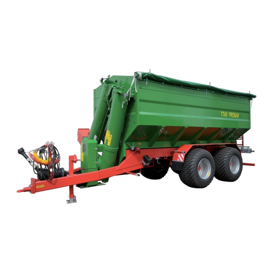
The manual describes the basic safety rules and operation of Pronar T740 trans-shipment
trailer. If the information contained in the Operator's Manual needs clarification then the user
should refer for assistance to the sale point where the machine was purchased or to the
Manufacturer.
MANUFACTURER'S ADDRESS:
CONTACT TELEPHONES
PRONAR Sp. z o.o.
ul. Mickiewicza 101A
17-210 Narew
+48 085 681 63 29
+48 085 681 63 81
this
Operator's Manual and observe all
+48 085 681 64 29
+48 085 681 63 82
Advertisement
Table of Contents

Related Manuals for PRONAR T740


Summary of Contents for PRONAR T740
- Page 1 The machine is designed to meet obligatory standards, documents and legal regulations currently in force. The manual describes the basic safety rules and operation of Pronar T740 trans-shipment trailer. If the information contained in the Operator's Manual needs clarification then the user should refer for assistance to the sale point where the machine was purchased or to the Manufacturer.
- Page 2 SYMBOLS APPEARING IN THIS OPERATOR'S MANUAL Information, descriptions of danger and precautions and also recommendations and prohibitions associated with user safety instructions are marked: and also preceded by the word "DANGER”. Failure to observe the instructions may endanger the machine operator's or other person's health or life. Particularly important information and instructions, the observance of which is essential, are distinguished in the text by the sign: and also preceded by the word "ATTENTION".
- Page 3 DIRECTIONS USED IN THIS OPERATOR'S MANUAL Left side – side to the left hand of the operator facing in the direction of machine's forward travel. Right side – side to the right hand of the operator facing in the direction of machine's forward travel.
-
Page 5: Table Of Contents
TABLE OF CONTENTS BASIC INFORMATION IDENTIFICATION 1.1.1 IDENTIFICATION OF TRANS-SHIPMENT TRAILER 1.1.1 AXLE IDENTIFICATION INTENDED USE FITTINGS WARRANTY CONDITIONS TRANSPORT 1.5.1 TRANSPORT ON VEHICLE 1.5.2 INDEPENDENT TRANSPORT BY THE USER 1.10 ENVIRONMENTAL HAZARDS 1.10 WITHDRAWAL FROM USE 1.11 SAFETY IN USE BASIC INFORMATION CONCERNING SAFE OPERATION OF THE MACHINE SAFETY DURING REPAIR AND MAINTENANCE WORK... - Page 6 CONSTRUCTION AND PRINCIPLE OF OPERATION SPECIFICATION CHASSIS 3.2.1 DRAWBAR EYE 3.2.2 TRAILER SUPPORT LOAD BOX FRONT CONVEYOR FRONT CHAIN TRANSMISSION 3.11 FRONT GEAR WHEEL TRANSMISSION 3.13 REAR CHAIN TRANSMISSION 3.14 WORKING BRAKE 3.15 PARKING BRAKE 3.20 3.10 TURNING INTERLOCK HYDRAULIC SYSTEM 3.21 3.11 HYDRAULIC SYSTEM SLIDE BOLT AND CONVEYOR 3.22...
- Page 7 PROPER USE AND MAINTENANCE OF TYRES 4.16 4.10 WEIGHER OPERATION 4.17 4.10.1 MOUNTING INDICATOR 4.17 4.10.2 STANDARD WORK 4.18 TECHNICAL MAINTENANCE PRELIMINARY INFORMATION TRANS-SHIPMENT TRAILER SERVICE INSPECTION 5.2.1 OPERATION NO. 1 - INSPECTION OF WHEEL AXLE BEARINGS 5.2.2 OPERATION NO. 2 - REGULATION OF MAIN BRAKE 5.2.3 OPERATION NO.
- Page 8 5.2.20 OPERATION NO. 20 – CHANGE OIL IN CONVEYOR INTERSECTING AXIS GEARING 5.32 UNLOADING SPEED REGULATION 5.34 5.3.1 ROOF HEIGHT REGULATION 5.34 5.3.2 REGULATION OF CHANNEL SLIDES IN GRAIN TANK 5.35 CONSUMABLES 5.37 5.4.1 HYDRAULIC OIL 5.37 5.4.2 GREASES 5.38 HYDRAULIC CLUTCH OPERATION 5.38 5.5.1...
-
Page 9: Basic Information
SECTION BASIC INFORMATION IDENTIFICATION INTENDED USE FITTINGS WARRANTY CONDITIONS TRANSPORT ENVIRONMENTAL HAZARDS WITHDRAWAL FROM USE... -
Page 10: Identification
1.1 IDENTIFICATION 1.1.1 IDENTIFICATION OF TRANS-SHIPMENT TRAILER FIGURE 1.1 Location of the data plate and serial number (1) data plate, (2) serial number The trailer is marked with the data plate (1), located on the right frame brace and the factory number (2) located on a gold painted rectangle. -
Page 11: Axle Identification
The meanings of the individual fields found on the data plate – figure (1.1) are presented in table (1.1). TABLE 1.1 Markings on data plate ITEM MARKING General description and purpose Symbol /Type Year of manufacture Seventeen digit serial number (VIN) Official certificate number Tare weight Maximum gross weight... -
Page 12: Intended Use
FRONT AXLE FACTORY NUMBER REAR AXLE FACTORY NUMBER 1.2 INTENDED USE The T740 trans-shipment trailer is constructed according to current safety requirements and engineering standards. The braking system and the light and indicator system meet the requirements of road traffic regulations. - Page 13 • familiarise himself with the contents of the operating instructions of the agricultural tractor, articulated telescopic shaft and weigher (if included in trailer equipment) and comply with these instructions. TABLE 1.1 THE AGRICULTURAL TRACTOR'S REQUIREMENTS CONTENTS UNIT REQUIREMENTS Brake system Pneumatic system 1 - conduit sockets compliant with A DIN 74 294 Pneumatic system 2 - conduit...
-
Page 14: Fittings
• for transporting people and animals, • using the machine to transport and trans-ship any materials other than those listed in the instructions. 1.3 FITTINGS TABLE 1.2 T740 TRANS-SHIPMENT TRAILER EQUIPMENT FITTINGS • OPERATING INSTRUCTIONS • WARRANTY BOOK • EZ 400 WEIGHER OPERATING INSTRUCTIONS •... -
Page 15: Warranty Conditions
Articulated telescopic shaft 1.4 WARRANTY CONDITIONS PRONAR Sp. z o.o., Narew guarantees the reliable operation of the machine when it is used according to its intended purpose as described in the OPERATOR'S MANUAL. The repair period is specified in the WARRANTY BOOK. -
Page 16: Transport
• by inappropriate use, adjustment or maintenance, use of the trailer for purposes other than those for which it is intended, • use of damaged machine, • repairs carried out by unauthorised persons, improperly carried out repairs, • making unauthorised alterations to machine design, the user will lose the right to warranty service. - Page 17 connected with the tractor according to the requirements closed in this Operators Manual. The trailer brake system must be started in checked before driving off or onto ramp. The trailer should be attached firmly to the platform of the vehicle using straps or chains fitted with a tightening mechanism.
-
Page 18: Independent Transport By The User
DANGER Incorrect application of securing measures may cause an accident. INDEPENDENT TRANSPORT BY THE USER In the event of independent transport by the user after purchase of the trailer, the user must read the trailer Operator's Manual and adhere to the recommendations contained therein. Independent transport involves towing the trailer with own agricultural tractor to destination. -
Page 19: Withdrawal From Use
DANGER Used hydraulic oil or gathered remains mixed with absorbent material should be stored in a precisely marked container. Do not use food packaging for this purpose. Oil, which has been used up or is unsuitable for further use owing to a loss of its properties should be stored in its original packaging in the conditions described above. - Page 20 Worn out or damaged parts that cannot be reclaimed should be taken to a collection point for recyclable raw materials. Hydraulic oil should be taken to the appropriate facility dealing with the re-use of this type of waste. 1.12...
-
Page 21: Safety In Use
SECTION SAFETY IN USE BASIC INFORMATION CONCERNING SAFE OPERATION OF THE MACHINE SAFETY DURING REPAIR AND MAINTENANCE WORK DANGERS DURING TRANS-SHIPMENT WORK HITCHING, UNHITCHING SAFETY PRINCIPLES WHEN WORKING WITH TYRES DANGERS DURING TRAVEL OPERATION OF ARTICULATED TELESCOPIC SHAFT SAFETY TIPS FOR HYDRAULIC CLUTCH OPERATION DESCRIPTION OF MINIMAL RISK INFORMATION AND WARNING STICKERS... -
Page 22: Basic Information Concerning Safe Operation Of The Machine
2.1 BASIC INFORMATION CONCERNING SAFE OPERATION OF THE MACHINE • Before using the trans-shipment trailer the user should thoroughly acquaint himself with the content of these instructions and the articulated telescopic shaft instructions. While using the machine, follow all the recommendations contained in these documents. -
Page 23: Safety During Repair And Maintenance Work
2.2 SAFETY DURING REPAIR AND MAINTENANCE WORK • Any modification to the trans-shipment trailer frees PRONAR Narew from any responsibility for damage or detriment to health, which may arise as a result. • It is recommended that necessary repairs to trans-shipment trailer should be undertaken by specialised workshops. - Page 24 • Do NOT change the settings of bolts placed on axle body limiting angle of axle turning (turning block bolts are set in the factory). Change of bolt settings may cause damage to braking system elements and damage to tyres. •...
-
Page 25: Dangers During Trans-Shipment Work
• Do NOT make repairs to drawbar eye (straightening, repairing or welding). Damaged drawbar eye should be replaced. • Reduce the oil or air pressure in the trans-shipment trailer before dismantling the hydraulic or pneumatic elements. • Regularly check the technical condition of the connections and the hydraulic and pneumatic leads. -
Page 26: Hitching, Unhitching
2.4 HITCHING, UNHITCHING • Be especially careful when attaching the machine. Ensure appropriate visibility and check that persons assisting in hitching the machine are at a safe distance from danger zone. • When attaching, there must be nobody between the trans-shipment trailer and the tractor. -
Page 27: Dangers During Travel
• Repair work on the wheels or tyres should be carried out by persons trained and entitled to do so. This work should be carried out using appropriately selected tools. • Regularly inspect the tightness of nuts securing the wheel to the axle according to the recommendations of the axle manufacturer. -
Page 28: Operation Of Articulated Telescopic Shaft
• When disconnected from the tractor the trans-shipment trailer must be secured by parking brake and wedges. • Do NOT move off or drive when support is lowered. FIGURE 2.1 Positioning of warning sign (1) warning sign, (2) attachment point 2.7 OPERATION OF ARTICULATED TELESCOPIC SHAFT •... - Page 29 • Never use a damaged articulated telescopic shaft, it may cause an accident. A damaged shaft must be repaired or replaced. • Disconnect the drive shaft each time when it is not necessary to drive the machine, or when the tractor and trans-shipment trailer are at an unsuitable angle to each other.
-
Page 30: Safety Tips For Hydraulic Clutch Operation
• Do NOT wear loose clothing, straps or whatever may become wrapped round the rotating drive shaft. Contact with rotating articulated telescopic shaft may cause severe injuries. • Do NOT go over and under the shaft or to stand on it equally during work as also when the machine is parked. -
Page 31: Description Of Minimal Risk
2.9 DESCRIPTION OF MINIMAL RISK Pronar Sp. z o. o. in Narew has made every effort to eliminate the risk of accidents. There is, however, a certain minimal risk which could lead to an accident, and this is connected mainly with the actions described below: •... -
Page 32: Information And Warning Stickers
• using strictly suited protective clothing, • ensuring unauthorised persons have no access to the machine, especially children. • maintaining the machine in due technical condition. 2.10 INFORMATION AND WARNING STICKERS The trans-shipment trailer is marked with information and warning stickers referred to in table (2.1). - Page 33 ITEM STICKER DESCRIPTION Danger of being pulled in by rotating auger conveyors. Do not approach and do not place hands near rotating mechanisms. Danger of crushing Do not place limbs in crushing danger zone. Attention! Do not stand on auger conveyors. Danger of being pulled in by rotating auger conveyors.
- Page 34 ITEM STICKER DESCRIPTION Danger of crushing to limbs. Take care when in the vicinity of rotating machine elements. Before entering load box or on platform disconnect tractor engine and remove key from ignition. Maximum rotation speed of Power Takeoff Shaft Check correct tightness of nut and bolt connections on axles.
- Page 35 ITEM STICKER DESCRIPTION Clearance warning sticker. Machine type Hydraulic clutch operation information sticker. 2.15...
- Page 36 ITEM STICKER DESCRIPTION Hydraulic connection function and hydraulic valves designation information sticker. Hydraulic valve lever position. Maximum vertical drawbar load Air pressure in the tyres 2.16...
- Page 37 FIGURE 2.2 Locations of information and warning stickers. Labelling in line with table (2.1). 2.17...
- Page 38 2.18...
-
Page 39: Construction And Principle Of Operation
SECTION CONSTRUCTION AND PRINCIPLE OF OPERATION SPECIFICATION CHASSIS LOAD BOX FRONT CONVEYOR FRONT CHAIN TRANSMISSION FRONT GEAR WHEEL TRANSMISSION REAR CHAIN TRANSMISSION WORKING BRAKE PARKING BRAKE TURNING INTERLOCK HYDRAULIC SYSTEM SLIDE BOLT AND CONVEYOR HYDRAULIC SYSTEM HYDRAULIC CLUTCH SYSTEM LIGHTING ELECTRIC SYSTEM WEIGHER ELECTRIC SYSTEM... -
Page 40: Specification
3.1 SPECIFICATION TABLE 3.1 TECHNICAL SPECIFICATION OF STANDARD FITTINGS CONTENTS UNIT T740 Dimensions Total length 9 142 Width 2 900 Height 3 645 LOAD BOX DIMENSIONS Length 6 038 Width 2 530 Maximum height 2 570 Technical specification LOAD BOX CAPACITY... -
Page 41: Chassis
CONTENTS UNIT T740 Maximum PTO speed revs 1 000 Minimal clutch working pressure Maximum clutch working pressure 3.2 CHASSIS Trans-shipment trailer chassis is shown on figure (3.1). The frame (1) is made as a welded structure from steel profiles. The main support elements are two longitudinal rails connected with crossbars. - Page 42 FIGURE 3.1 Trans-shipment trailer chassis (1) lower frame, (2) suspension, (3) front axle, (4) rear axle, (5) drawbar eye, (6) PTO connection, (7) wheel, (8) mudguard, (9) rear lighting beam, (10) weight simulator / loading link cell, (11) support, (12) conduit bracket...
-
Page 43: Drawbar Eye
3.2.1 DRAWBAR EYE As a standard, the T740 trans-shipment trailer is equipped with rotating eye of internal diameter ∅50 mm. At the client's request the machine may be equipped with ball hitch of diameter ∅80 mm. Both types of hitching connections are secured to the head plate (3) of the drawbar with 6 bolts. - Page 44 maximally raised and secured using pin (5), and crank (3) setting neutral position (A). The support is equipped with two gear gearing mechanism. Setting is changed by pulling crank to position (C) or pressing it into position (B). FIGURE 3.3 Trans-shipment trailer support (1) support (2) support foot, (3) crank, (4) gearing, (5) securing pin, (A) neutral position (B) gear position I , (C) gear position II...
-
Page 45: Load Box
3.3 LOAD BOX FIGURE 3.4 Load box construction (1) load box (container), (2) height extension set, (3) cover tilt, (4) rear platform, (5) ladder, (6) rear chain gearing, (7) chute slide, (8) inspection cover The load box is constructed as a welded construction and seated on the lower frame with the aid of weight simulators or loading link cells. - Page 46 FIGURE 3.5 Load box construction (1) auger conveyor IX (rear), (2) auger conveyor X (left front), (3) auger conveyor XI (right front), (4) auger conveyor VIII (collecting), (5) auger intake control roof, (6) channel slide cover, (7) bearing connector On the front wall of the load box (inside container) all their intake control roof is bolted to brace (5) –...
-
Page 47: Front Conveyor
Speed of inflow of grain to container channel depends on the setting of channel slides (6), placed over conveyors. Auger conveyors transporting grain in container channels have a variable pitch, which prevents blocking during unloading and enables even transport of grain from rear part of low box to the collecting auger conveyor. - Page 48 FIGURE 3.6 Front conveyor (1) vertical conveyor, (2) folding conveyor, (3) conveyor hinge, (4) chute, (5) folding ram / unfolding conveyor, (6) ram bolting folded conveyors, (7)collection pipe 3.10...
-
Page 49: Front Chain Transmission
FIGURE 3.7 Bolting method (1) ram unbolting folded conveyor, (2) ram folding/unfolding conveyor, (3) spring, (4) striker, (5) spring, (6) locking bolt 3.5 FRONT CHAIN TRANSMISSION Front chain transmission transmits torque to the two auger conveyors placed in container and front auger conveyor. - Page 50 FIGURE 3.8 Front chain transmission (1) hydraulic clutch, (2) drive shaft, (3) collecting auger conveyer shaft, (4) intersecting axis gearing, (5) toothed cog securing pin, (6) abrasive friction clutch, (7) exit shaft housing , (8) gear wheel transmission (two gears), (9) pressure gauge Power transmission shaft (2) is connected through PTO shaft and articulated shaft to PTO of tractor.
-
Page 51: Front Gear Wheel Transmission
engaging PTO drive and after initiation of hydraulic clutch (1). The torque is transmitted via gear wheels to intersecting axis gearing (4), which drives two auger conveyors mounted in the front conveyor. Next, the torque is transmitted to further receivers – the collecting auger conveyor (3) and two auger conveyors (divided) placed in container. -
Page 52: Rear Chain Transmission
FIGURE 3.9 Front gear wheel transmission (1) gear wheel transmission, (2) drive shaft (3) setting change lever, (A) neutral position, (B) RAPID REVOLUTIONS position, (C) SLOW REVOLUTIONS position 3.7 REAR CHAIN TRANSMISSION Rear chain transmission is mounted on container wall. It transmits torque from auger conveyors placed in channel on the right side of the container to 2 conveyors placed on the left side of the container. -
Page 53: Working Brake
FIGURE 3.10 Rear chain transmission (1) Rear right auger conveyer shaft, (2) rear left auger conveyer shaft, (3) tightening cog 3.8 WORKING BRAKE The trans-shipment trailer is equipped with one of three types of working brake installations (pneumatic brakes): • two conduit pneumatic system with three position braking force regulator - figure (3.11) –... - Page 54 FIGURE 3.11 Two conduit pneumatic system diagram with three position regulator (1) air tank, (2) control valve, (3) brake force regulator, (4) pneumatic ram, (5), (6) lead connectors, (7) air filter, (8) air tank control connectors (9) drain valve Working brake is activated from the tractor driver's cab by pressing on the brake pedal in the tractor.
- Page 55 FIGURE 3.12 Single conduit pneumatic system diagram with three position regulator (1) air tank, (2) control valve, (3) brake force regulator, (4) pneumatic ram, (5), (6) lead connectors, (6) air filter, (7) air tank control connectors (8) drain valve Brake pneumatic cylinders applied in the systems are mounted on specially prepared brackets welded to the axle.
- Page 56 FIGURE 3.13 Two conduit pneumatic system diagram with an automatic regulator (1) air tank, (2) control valve, (3) automatic brake force regulator, (4) transmission valve, (5) pneumatic cylinder, (6), (7) lead connectors, (8) air filter, (9) drain valve (10) air tank control connectors In two conduit braking system, with automatic braking force regulator, an additional transmission valve is mounted (4), the function of which is to significantly increase the speed...
- Page 57 FIGURE 3.14 Three position manual regulator (1) three-step brake force regulator, (2) regulator setting control lever, (A), (B), (C) regulator operation position Three-step brake force regulator - figure (3.9), applied in pneumatic systems adjusts braking force depending on setting. Switching to a suitable working mode is done manually by machine operator with the aid of the lever (2) prior to moving off.
-
Page 58: Parking Brake
Additionally, each pneumatic connection is equipped with a cut-off valve, which automatically cuts off outflow of pneumatic conduit in the event of disconnection from agricultural tractor socket. 3.9 PARKING BRAKE FIGURE 3.15 Parking brake (1) parking brake crank mechanism, (2) handle with wheel, (3) axle expander lever, (4) steel cable The parking brake is for immobilising trans-shipment trailer while standing motionless. -
Page 59: Turning Interlock Hydraulic System
causes tilting of the expander lever, which parts the jaws of the brake shoes immobilising the trans-shipment trailer. 3.10 TURNING INTERLOCK HYDRAULIC SYSTEM Trans-shipment trailer as standard equipment in passively steered turning rear axle. Axle design enables easier cornering and easier manoeuvring on marshy terrain, due to which there is less tyre wear on machine. -
Page 60: Hydraulic System Slide Bolt And Conveyor
Turning interlock system hydraulic connections are marked with blue coloured stoppers, as stated by sticker (5). 3.11 HYDRAULIC SYSTEM SLIDE BOLT AND CONVEYOR FIGURE 3.17 Slide bolt and conveyor hydraulic system concept diagram (1) quick couplers, (2) hydraulic valve, (3) slide bolt cylinder, (4) folded conveyor raising cylinder, (5) folded conveyor bolting cylinder 3.22... - Page 61 FIGURE 3.18 Placing of elements of hydraulic slide bolt and conveyor installation (1) folded conveyor raising cylinder, (2) folded conveyor bolting cylinder, (3) locking bolt cylinder, (4) hydraulic valve, (5) quick couplers, (6) slide bolt, (7) cylinder bracket, (8), (9) information sticker System design and concept diagram are presented on figures (3.17) and (3.18).
-
Page 62: Hydraulic Clutch System
• raising / lowering folded conveyor, • locking / unlocking folded conveyor, • opening / closing container channels slide. Connecting individual circuits for work takes place manually by the machine operator with the aid of hydraulic valves (4) – figure (3.18), placed on bracket. Valve set in position 1 directs hydraulic oil stream to cylinders (1) and (2). - Page 63 FIGURE 3.19 Position of hydraulic clutch system elements (1) reduction valve connection plate, (2) hydraulic valve, (3) pressure gauge, (4) quick couplers, (5) return valve, (6) rotary connection, (7) information sticker IMPORTANT! After connecting agricultural tractor trans-shipment trailer regulate the reduction valve (1) –...
- Page 64 Hydraulic oil pressure range for starting clutch is 90-95 bar. Cut-off valve (2) is designed for cutting off hydraulic oil in flow to clutch during working pressure regulation of system. In the course of normal use it must be set in open position. Quick coupler terminals are marked with black coloured stoppers, as stated on information sticker (7).
-
Page 65: Electric Lighting System
3.13 ELECTRIC LIGHTING SYSTEM FIGURE 3.21 Electric lighting system diagram Description of markings in table (3.2) 3.27... - Page 66 TABLE 3.2 LIST OF MARKINGS APPLIED ON FIGURE (3.21) SYMBOL FUNCTION Rear right light combination group Rear left light combination group Front seven pin socket 3-pin plug Cigarette lighter supply plug Rear right clearance light Rear left clearance light Right registration plate light Left registration plate light Working light Trans-shipment trailer electric lighting system is adapted to supply from direct current source...
-
Page 67: Electric Weighing System Installation
TABLE 3.4 CONDUIT COLOUR MARKING MARKING CONDUIT COLOUR MARKING CONDUIT COLOUR White Brown Black Orange Violet Pink Grey Lazurite Green Blue Yellow Working lamp placed on vertical conveyor is supplied from 12V DC socket mounted on rear of tractor. 3.14 ELECTRIC WEIGHING SYSTEM INSTALLATION Trans-shipment trailer may be equipped with transported load weighing system. - Page 68 FIGURE 3.22 Lighting panel Description of markings on table (3.5) 3.30...
- Page 69 FIGURE 3.23 Weighing system diagram (1) counter, (2) rubber vacuum cup, (3) load cell connection socket, (4) power supply socket Counter (1) is mounted in tractor operator cab on bracket with rubber suction pad. Power supply to counter and whole weighing system is through connection conduit connected with the lighter socket in the tractor.
- Page 70 3.32...
-
Page 71: Correct Use
SECTION CORRECT USE PREPARING FOR WORK BEFORE FIRST USE ATTACHING TO TRACTOR TRANS-SHIPMENT TRAILER SUPPORT OPERATION LOADING SECURING LOAD TRAILER TRANSPORT UNLOADING DISCONNECTING FROM TRACTOR PROPER USE AND MAINTENANCE OF TYRES WEIGHER OPERATION... -
Page 72: Preparing For Work Before First Use
4.1 PREPARING FOR WORK BEFORE FIRST USE The manufacturer guarantees that the trans-shipment trailer is fully operational and has been checked according to quality control procedures and is ready for normal use. This does not release the user from an obligation to check the machine's condition after delivery and before first use. - Page 73 • Check if the nuts and bolts fixing the wheels, the drawbar and front conveyor are properly tightened, • Drain air tank of the brake system. • Ensure that pneumatic, hydraulic and electric connections in agricultural tractor are according to the requirements, if not the trans-shipment trailer should not be hitched to the tractor.
- Page 74 • Disconnect PTO drive, turn off tractor engine, unhitch trans-shipment trailer from tractor. Service operation hitching/unhitching from tractor, regulation of clutch pressure supply etc. are described in detail in further parts of the instructions. The trans-shipment trailer may be hitched only when all preparatory activities including inspection of technical condition have been completed satisfactorily.
-
Page 75: Attaching To Tractor
4.2 ATTACHING TO TRACTOR Ensure that pneumatic, hydraulic and electric connections and the hitch of agricultural tractor are according to the Manufacturer's requirements, if not the trans-shipment trailer should not be hitched to the tractor. In order to hitch the trans-shipment trailer to the tractor perform the actions below in the sequence presented. - Page 76 • Connect to conduit hydraulic clutch system (black). Conduit with mounted return valve should be connected to socket "slow pouring” by-passing hydraulic manifold. DANGER When hitching, there must be nobody between the trailer and the tractor. When hitching the machine, tractor driver must exercise caution and make sure that nobody is present in the hazard zone.
-
Page 77: Trans-Shipment Trailer Support Operation
ATTENTION! Trans-shipment trailer may only be hitched to a tractor, which has the appropriate connection sockets for braking, hydraulic and electrical, and hydraulic oil in both machines is the same type and also the tractor hitch is capable of bearing the vertical drawbar loading of the loaded trailer. - Page 78 FIGURE 4.1 FOLD SUPPORT LEG (1) support (2) support foot, (3) crank, (4) gearing, (5) securing pin, (A) neutral position (B) gear position I , (C) gear position II Lowering support • Remove safety pin. • Set crank in position (B) or (C). •...
-
Page 79: Loading
IMPORTANT! Do not move and drive with lowered support. 4.4 LOADING Load box can be loaded only when the trailer is connected to the tractor and positioned horizontally. Always aim at distributing the load uniformly in the load box. This will ensure stability when travelling and correct axle and drawbar loads. -
Page 80: Securing Load
With regard to the varying density of materials, using the total load box capacity may cause exceeding permissible carrying capacity of the trailer. ATTENTION! Do NOT exceed permissible load weight of trailer because this may cause danger while travelling and cause damage to the machine. 4.5 SECURING LOAD Regardless of the type of load carried, the user is obliged to secure it in such a manner that the load is unable to spread and cause contamination of the road. -
Page 81: Transporting The Trailer
FIGURE 4.2 TARPAULIN COVER (1) crank strip, (2) tarpaulin cover, (3) strap clamp, (4) fastening strap 4.6 TRANSPORTING THE TRAILER When travelling on public or private roads, respect the road traffic regulations, exercise caution and prudence. Listed below are the key guidelines for driving the tractor and trailer combination. - Page 82 • Raise trans-shipment trailer support and secure it in transport position. • Ensure that trans-shipment trailer is properly hitched to the tractor and that the tractor hitch has been properly secured. • While reversing immobilise rear turning axle with the aid of turning interlock cylinder rams.
-
Page 83: Unloading
• Speed must be sufficiently reduced before making a turn or driving on an uneven road or a slope. • During reversing one should use the assistance of another person, who gives directions standing clear of the danger zone. 4.7 UNLOADING Unloading with the aid of vertical conveyor FIGURE 4.3 GEAR WHEEL TRANSMISSION... - Page 84 • Start tractor PTO at speed of approx. 500 revs (auger conveyor begins to rotate). • Using tractor manifold lever start hydraulic clutch (drive to container augers is started). Gradually increase PTO revs, until a speed of 1,000 revs is reached. •...
-
Page 85: Disconnecting From Tractor
• Disconnect clutch. Operation of auger conveyors in container must be short enough so that grain from the collecting shaft does not reach the vertical conveyor. • During unloading monitor working pressure of hydraulic clutch. During unloading using the channel chute there is no need to unfold the vertical conveyor. The load from the container shall pour directly to the reception hopper grating. -
Page 86: Proper Use And Maintenance Of Tyres
• Unhitch trans-shipment trailer drawbar eye from tractor hitch and drive tractor away. Wheel wedges shall be so placed that one of the is in front of the wheel and the second is behind it. Pneumatic system conduits must be placed in the sockets designed for this purpose positioned on the drawbar bracket. -
Page 87: Weigher Operation
4.10 WEIGHER OPERATION 4.10.1 MOUNTING INDICATOR Weight indicator should be placed in tractor operator cab. Panel should be secured with the aid of rubber suction to windscreen. Select mounting place, we are indicator shall be visible and animal operation will not cause difficulty during driving the tractor. After securing indicator then connect conduit supply connecting attached to weighing system. -
Page 88: Standard Work
Power supply and signal lead plugs are so designed that it is impossible to connect them incorrectly to the indicator panel. 4.10.2 STANDARD WORK Switching weigher on. • Press ON/OFF button . A short HELLO message appears. Weigher moves into weighing mode GROSS (total weight). -
Page 89: Technical Maintenance
SECTION TECHNICAL MAINTENANCE PRELIMINARY INFORMATION TRANS-SHIPMENT TRAILER SERVICE INSPECTION UNLOADING SPEED REGULATION CONSUMABLES HYDRAULIC CLUTCH OPERATION THOROUGH LOAD TANK CLEANING CLEANING TRANS-SHIPMENT TRAILER STORAGE TIGHTENING TORQUE FOR NUT AND BOLT CONNECTIONS LIST OF BULBS FAULTS AND MEANS OF REMEDYING THEM... -
Page 90: Preliminary Information
5.1 PRELIMINARY INFORMATION When using the trans-shipment trailer, regular inspections of its technical condition are essential and the performance of maintenance procedures, which keep the machine in good technical condition. In connection with this the user of the trans-shipment trailer is obliged to perform all the maintenance and regulation procedures defined by the Manufacturer. - Page 91 • Cleaning the air filters • • Inspection of hydraulic system tightness • • Inspection of lighting and signalling system Inspection of nut and bolt tightness on See 5.2.12 wheels and drawbar Inspection of greasing points According to schedule • Technical inspection of wheels Regulation of working pressure of clutch See 5.2.15...
- Page 92 TABLE 5.2 INSPECTION PERFORMANCE FREQUENCY INSPECTION DESCRIPTION Perform service after first travel of trans-shipment trailer After first use (without load) - once only inspection. Perform service after first travel of trans-shipment trailer After first travel with load (with load) - once only inspection. Perform inspection after first week of normal use of After a week of use trans-shipment trailer –...
-
Page 93: Operation No. 1 - Inspection Of Wheel Axle Bearings
5.2.1 OPERATION NO. 1 - INSPECTION OF WHEEL AXLE BEARINGS In a newly purchased trailer, after the first week of use or covering a distance of 100 km, while during further use – after 6 months of vehicle use check and regulate wheel axle bearings when needed. -
Page 94: Operation No. 2 - Regulation Of Main Brake
• Grasp wheel above and below and try to feel any slack play, this may equally be checked with the aid of a jack placed under the wheel supported on the floor/ground. If slack is felt, adjust bearing. Unusual sounds coming from bearing may be symptoms of excess wear, dirt or damage. - Page 95 • as a result of wear of brake shoe linings between lining and drum there is excessive slack and reduced braking effectiveness. • wheel brakes do not brake evenly or simultaneously. • repairs are made to braking system If brakes are correctly regulated, braking of trans-shipment trailer road wheels takes place simultaneously.
-
Page 96: Operation No. 3 - Regulation Of Parking Brake
any construction elements, because too little withdrawal of a piston ram may cause abrasion of brake shoes in drum and result in overheating trans-shipment trailer brakes. Inspection and regulation of main brake: • Every 12 months • if needed. ATTENTION! Main brake braking force, is the braking force of all trans-shipment trailer wheels. -
Page 97: Operation No. 4 - Draining Water From The Air Tank
• tighten cable and tighten clamps. Length of parking brake cable should be so selected that at total release of working and parking brake the cable would be loose and hanging by 1 - 2 cm. Inspection and regulation of parking brake: •... -
Page 98: Operation No. 5 - Cleaning Drain Valve
Required service actions • Open out drain valve (2) placed in lower part of tank. • The compressed air in the tank causes the removal of water to the exterior. After release valve mandrel should automatically close and stop air flow from tank. -
Page 99: Operation No. 6 - Inspection Of Connections
5.2.6 OPERATION NO. 6 - INSPECTION OF CONNECTIONS Required service actions • Check technical condition of bodies of pneumatic, hydraulic and electrical connectors. • Check electric contacts. • Check condition of pneumatic connector seals, check condition of safety covers. Damage including cracking of body, burnt or broken electrical contacts, damage thread classifies contact for replacement. -
Page 100: Operation No. 8 - Inspection Of Braking System Tightness
sideways, if there is an insignificant pressure drop in braking system one should consider the system to be reliable. A metallic noise during braking, rapid heating of brake drums, uncontrolled slips sideways, jerking of trailer, too low air pressure, sudden pressure drop or other symptoms appearing during braking may be the cause of brake shoe lining wear, damage connectors or conduits, unreliability of control valve or other serious system faults. -
Page 101: Cleaning The Air Filters
Contact of pneumatic leads with oils, greases, petrol etc. may cause damage and accelerate ageing process. Bent conduits, permanently deformed, cut or worn should be replaced. Tightness inspection: • After a week of use • Every 12 months of use. 5.2.9 CLEANING THE AIR FILTERS Depending on trailer working conditions, but not less than once in three months, take out and clean air filter inserts, which are placed in pneumatic system connection conduits. -
Page 102: Operation No. 10 - Inspection Of Hydraulic System Tightness
FIGURE 5.4 AIR FILTER (1) securing slide lock, (2) air filter cover 5.2.10 OPERATION NO. 10 – INSPECTION OF HYDRAULIC SYSTEM TIGHTNESS Required service actions • Hitch trans-shipment trailer to tractor. • Connect all hydraulic system conduits according to service instructions. •... -
Page 103: Operation No. 11 - Inspection Of Lighting And Signalling System
ATTENTION! The trans-shipment trailer and tractor must not be attached if the hydraulic oil in the two machines is of different types. Do not use the trans-shipment trailer with damaged hydraulic system. Tightness inspection: • After a week of use •... -
Page 104: Operation No. 12 - Inspection Of Tightness Of Wheels And Drawbar Nuts And Bolt Connections
Annual inspection of system does not relieve user of daily inspection of technical condition of lighting system. 5.2.12 OPERATION NO. 12 - INSPECTION OF TIGHTNESS OF WHEELS AND DRAWBAR NUTS AND BOLT CONNECTIONS FIGURE 5.5 TIGHTENING WHEELS NUTS (1) - (10) sequence of nut tightening, (L) spanner length, (F) user weight Inspection of wheel axle and drawbar eye tightening: •... -
Page 105: Operation No.9 - Inspection Of Greasing Points
TABLE 5.3 SPANNER ARM WHEEL TIGHTENING TORQUE BODY WEIGHT (F) ARM LENGTH (L) [Nm] [kg] 0.75 0.65 0.55 0.50 Drawbar eye tightness should be checked simultaneously with wheel nut tightness checking. Tightening torque should amount to 240 Nm. Nuts should be tightened gradually diagonally, using torque spanner. - Page 106 ITEM GREASING POINT Lever Expander shaft bracket sleeve Expander shaft sleeve in drum hub Support gearing Leaf spring absorbers Multi-flanged terminal of articulated telescopic shaft Rotating drawbar eye Sleeve Leaf spring absorber sliding surfaces Striker sleeve Sliding bearing of folding conveyor cylinder ram Lock sleeve Bolting ram securing pin Self-centering bearing...
- Page 107 ITEM GREASING POINT Cylinder bolt and pin Hinge pin Parking brake mechanism Parking brake guide rollers pin Chain Bearing assembly Front gear wheel transmission 500H Shaft elbows the first oil change is carried out after 50 hours work, comply with the instructions of shafts Manufacturer, greasing periods –...
- Page 108 FIGURE 5.6 TRAILER GREASING POINTS - CHASSIS 5.20...
- Page 109 FIGURE 5.7 TRAILER GREASING POINTS – VERTICAL CONVEYOR 5.21...
- Page 110 FIGURE 5.8 TRAILER GREASING POINTS – PARKING BRAKE FIGURE 5.9 TRAILER GREASING POINTS – REAR CHAIN GEARING 5.22...
- Page 111 FIGURE 5.10 TRAILER GREASING POINTS – FRONT CHAIN GEARING 5.23...
- Page 112 FIGURE 5.11 TRAILER GREASING POINTS – GATHERING AUGER SHAFT AND CONTAINER AUGER SHAFT BEARING ASSEMBLY Trailer greasing should be performed with the aid of a manually or foot operated grease gun, filled with generally available permanent grease based on lithium or lime soap. Before beginning greasing in so far as is possible remove old grease and other contamination.
-
Page 113: Operation No. 14 - Technical Inspection Of Wheels
Thoroughly wash accumulated deposits off parabolic leaf springs and then after drying grease internal surfaces of leaves with anticorrosion and greasing preparation. When using the trans-shipment trailer, the user is obliged to observe greasing instructions according to greasing schedule. 5.2.14 OPERATION NO. 14 - TECHNICAL INSPECTION OF WHEELS Tyre pressure should be checked each time after changing spare wheel and not less than every 3 months. - Page 114 Required service actions FIGURE 5.12 REGULATION OF WORKING PRESSURE OF CLUTCH (1) reduction valve, (2) cut-off valve, (3) connection plate, (4) pressure gauge, (5) information sticker • Hitch trans-shipment trailer to tractor. 5.26...
-
Page 115: Operation No. 16 - Inspection Of Tightness Of Front Chain Gearing (I Stage)
• Immobilise tractor and trailer with parking brake. • Set cut-off valve (2) in (Z) position – closed. • Start tractor, using hydraulic manifold supplying hydraulic clutch system. • Using reduction valve (1), placed on connection plate (3) regulate pressure in clutch system. -
Page 116: Operation No. 17 - Inspection Of Tightness Of Front Chain Transmission (Ii Stage)
• After achieving required tightness, tighten counter nut (4). FIGURE 5.13 I STAGE OF FRONT CHAIN GEARING (1) chain, (2) tensioner toothed cog, (3) tensioner bolt, (4) counter nut, (5) tightening nut Check drive chain tightness of the I stage of transmission gear: •... - Page 117 Required service actions • Immobilise tractor and trailer with parking brake. • Put two wedges behind the wheel, to stop machine rolling. Check drive chain tightness of the III stage of transmission gear: • every 10 hours of work - before greasing chain. FIGURE 5.14 II STAGE OF FRONT CHAIN TRANSMISSION (1) chain, (2) connector housing, (3) tensioner bolt, (4) bolt connection, (5) tensioner toothed...
-
Page 118: Operation No.18 - Inspection Of Tightness Of Rear Chain Transmission
• If there is an excessive looseness, loosen tensioner bolt (6) and tighten chain (1) while lifting the wheel. Tensioner block, joined with tensioner toothed cog (5) is moved upwards. • After achieving required tightness, tighten tensioner bolt (6). • If there is still an excessive looseness in the transmission, loosen 4 nuts (4) and tighten chain (1) using adjustment bolt (3) –... -
Page 119: Operation No. 19 - Change Oil In Front Gear Wheel Transmission
• Put two wedges behind the wheel, to stop machine rolling. • Open transmission cover. • Check chain looseness. Press with thumb in mid-length (place marked with arrow), chain loose play should amount to 7 - 15 mm. • If there is greater looseness then loosen counter nut (4), and nut (5) tighten chain (1). -
Page 120: Operation No. 20 - Change Oil In Conveyor Intersecting Axis Gearing
FIGURE 5.16 FRONT GEAR WHEEL TRANSMISSION (1) oil drain plug, (2) oil filler plug First oil change should be performed after working 50 hours and then after every 500 hours of work. Check gearing each month for oil leaks and mechanical damage. 5.2.20 OPERATION NO. - Page 121 • Unscrew inlet plug (2) - inlet plug is on the opposite side to the drain plug (1). • Unscrew drain plug (1). • Drain used oil into container. • Tighten drain plug. • Pour in new oil (2.3 litres). •...
-
Page 122: Unloading Speed Regulation
5.3 UNLOADING SPEED REGULATION The unloading time of grain (with the assumption that the PTO revolution speed is constant), is dependent on several factors: • setting of front gear wheel transmission, • roof cover position, • grain tank channel slides position. Recommended settings are shown in table below. -
Page 123: Regulation Of Channel Slides In Grain Tank
FIGURE 5.18 ROOF HEIGHT REGULATION (1) roof, (2) bolt connection Roof position regulation must be performed with empty grain tank. DANGER Before entering grain tank switch off tractor engine, disconnect articulated telescopic shaft, immobilise trans-shipment trailer using parking brake and secure tractor against access of unauthorised persons. - Page 124 • Dismantle articulated telescopic shaft, connecting tractor with machine (if trans- shipment trailer is connected to tractor). • Loosen two nuts (2). • Move channel slide choosing appropriate setting. • Tighten both nuts. • repeat action for remaining channel slides, maintaining constant distance of slide sheets from tank sides in all elements.
-
Page 125: Consumables
Channel slide position regulation must be performed with empty grain tank. DANGER Before entering grain tank switch off tractor engine, disconnect articulated telescopic shaft, immobilise trans-shipment trailer using parking brake and secure tractor against access of unauthorised persons. 5.4 CONSUMABLES 5.4.1 HYDRAULIC OIL Always adhere to the principle that the oil in the trans-shipment trailer hydraulic system and in the tractor hydraulic system are the same type. -
Page 126: Greases
(petrol, kerosene). Contaminated clothing should be changed to prevent access of oil to skin. In the event of contact of oil with eye, rinse with large quantity of water and in the event of the occurrence of irritation consultant a doctor. Hydraulic oil in normal conditions is not harmful to the respiratory tract. -
Page 127: Tightening Torque For Nut And Bolt Connections
• Permissible loading and maximum revs may not be exceeded. • Attention should be given to the tightness of oil conduits and connections in steering parts. • Incorrect dismantling of clutch may lead to damage the body. Pay attention that the clutch is under spring tension. -
Page 128: Thorough Load Tank Cleaning
5.6 THOROUGH LOAD TANK CLEANING Change of grain type requires thorough cleaning of trailer tank to remove remains of previous load. The chute slide, inspection covers and conveyor covers are used for this purpose, which should be opened before beginning work. Compressed air is recommended for thorough cleaning of tank. - Page 129 pneumatic, electric and hydraulic plugs, lights, electrical connections, information and warning stickers, identification plates, hydraulic clutch, chain gears etc. Great water jet pressure may damage these elements. • Do not direct water jet at individual trailer greasing points. • For cleaning and maintenance of plastic coated surface it is recommended to use clean water or special preparations designed for this purpose.
-
Page 130: Storage
• Observe environmental protection principles and wash trans-shipment trailer in a place designated for such purpose. 5.8 STORAGE Trans-shipment trailer should be stored in a completely enclosed or roofed building. If the trans-shipment trailer will not be used for a long time, it is essential to protect it from adverse weather, especially rust and accelerated tyre deterioration. - Page 131 TABLE 5.8 TIGHTENING TORQUE FOR NUT AND BOLT CONNECTIONS 10.9 THREAD METRIC [Nm] 1 050 1 150 1 650 1 050 1 450 2 100 – resistance class according to DIN ISO 898 standard FIGURE 5.20 BOLT WITH METRIC THREAD (1) resistance class, (d) thread diameter 5.43...
-
Page 132: List Of Bulbs
5.10 LIST OF BULBS TABLE 5.9 LIST OF BULBS LAMP BULB R10W – 4 units Rear lamp group P21W – 4 units. PY21W – 1 unit. T4W – 1 unit. License plate light C5W – 1 unit. – Number of bulbs applies to one lamp 5.11 FAULTS AND MEANS OF REMEDYING THEM TABLE 5.10 FAULTS AND MEANS OF REMEDYING THEM... - Page 133 FAULT CAUSE REMEDY brake force regulator Check slack and regulate if Excessive slack in bearings needed Noise in axle hubs Damaged bearing Replace bearing Incorrect main or parking Regulate setting of expander arms Excessive heating of axle brake regulation hubs Worn brake linings Change brake shoes Check oil quality, make sure that...
- Page 134 FAULT CAUSE REMEDY Insufficient working Check pressure and set at pressure required value. Springs slips because oil Check pressure and set at Clutch heats to over pressure is too low required value. 120°C when connected Worn out abrasive ring Install a new abrasive ring Restore slow rotation to cone Cone shield resting on pin shield on pins.
- Page 135 NOTES ………………………………………………………………………………………………………………………………….. ………………………………………………………………………………………………………………………………….. ………………………………………………………………………………………………………………………………….. ………………………………………………………………………………………………………………………………….. ………………………………………………………………………………………………………………………………….. ………………………………………………………………………………………………………………………………….. ………………………………………………………………………………………………………………………………….. ………………………………………………………………………………………………………………………………….. ………………………………………………………………………………………………………………………………….. ………………………………………………………………………………………………………………………………….. ………………………………………………………………………………………………………………………………….. ………………………………………………………………………………………………………………………………….. ………………………………………………………………………………………………………………………………….. ………………………………………………………………………………………………………………………………….. ………………………………………………………………………………………………………………………………….. ………………………………………………………………………………………………………………………………….. ………………………………………………………………………………………………………………………………….. ………………………………………………………………………………………………………………………………….. ………………………………………………………………………………………………………………………………….. ………………………………………………………………………………………………………………………………….. ………………………………………………………………………………………………………………………………….. ………………………………………………………………………………………………………………………………….. ………………………………………………………………………………………………………………………………….. ………………………………………………………………………………………………………………………………….. ………………………………………………………………………………………………………………………………….. …………………………………………………………………………………………………………………………………..
- Page 136 ………………………………………………………………………………………………………………………………….. ………………………………………………………………………………………………………………………………….. ………………………………………………………………………………………………………………………………….. ………………………………………………………………………………………………………………………………….. ………………………………………………………………………………………………………………………………….. ………………………………………………………………………………………………………………………………….. ………………………………………………………………………………………………………………………………….. ………………………………………………………………………………………………………………………………….. ………………………………………………………………………………………………………………………………….. ………………………………………………………………………………………………………………………………….. ………………………………………………………………………………………………………………………………….. ………………………………………………………………………………………………………………………………….. ………………………………………………………………………………………………………………………………….. ………………………………………………………………………………………………………………………………….. ………………………………………………………………………………………………………………………………….. ………………………………………………………………………………………………………………………………….. ………………………………………………………………………………………………………………………………….. ………………………………………………………………………………………………………………………………….. ………………………………………………………………………………………………………………………………….. ………………………………………………………………………………………………………………………………….. ………………………………………………………………………………………………………………………………….. ………………………………………………………………………………………………………………………………….. ………………………………………………………………………………………………………………………………….. ………………………………………………………………………………………………………………………………….. ………………………………………………………………………………………………………………………………….. ………………………………………………………………………………………………………………………………….. ………………………………………………………………………………………………………………………………….. ………………………………………………………………………………………………………………………………….. ………………………………………………………………………………………………………………………………….. …………………………………………………………………………………………………………………………………..
Need help?
Do you have a question about the T740 and is the answer not in the manual?
Questions and answers