Table of Contents
Advertisement
Quick Links
PRONAR SP. Z O.O.
17-210 NAREW, UL. MICKIEWICZA 101A, WOJ. PODLASKIE
TEL.:
+48 085 681 63 29
+48 085 681 63 81
FAX:
+48 085 681 63 83
USER MANUAL
SEPTIC TANKER
PRONAR TG110
TRANSLATION OF THE ORIGINAL MANUAL
EDITION NO. 649.01.UM.1A.EN
ISSUE 1A
08-2022
+48 085 681 64 29
+48 085 681 63 82
+48 085 682 71 10
Advertisement
Table of Contents

Related Manuals for PRONAR TG110


Summary of Contents for PRONAR TG110
- Page 1 PRONAR SP. Z O.O. 17-210 NAREW, UL. MICKIEWICZA 101A, WOJ. PODLASKIE TEL.: +48 085 681 63 29 +48 085 681 64 29 +48 085 681 63 81 +48 085 681 63 82 FAX: +48 085 681 63 83 +48 085 682 71 10...
- Page 2 Copyright © PRONAR Sp. z o.o. All rights reserved. This study is the property of PRONAR Sp. z o.o. and is a work within the meaning of the Copyright and Related Rights Act. Any part of this document may not be distributed or copied in any way (electronic, mechanical or otherwise) without the written...
-
Page 3: Table Of Contents
1.8.7 Safety glasses with side shields 1.22 1.8.8 Industrial protective helmet 1.22 1.8.9 Anti-dust respirator 1.23 CHAPTER 2 GENERAL 2.1 Identification 2.1.1 Machine identification 2.1.2 Driving axle identification 2.2 Intended use of the machine 2.2.1 Using the machine in accordance with intended use Pronar TG110... - Page 4 4.6.2 Hydraulic system of the docking mechanism 4.15 4.7 Electrical lighting installation 4.18 CHAPTER 5 CONTROL PANEL 5.1 Control system 5.1.1 Main control pilot 5.1.2 Additional remote control 5.1.3 Inductive sensors CHAPTER 6 RULES OF USE 6.1 Drawbar height adjusting Pronar TG110...
- Page 5 7.18 The pneumatic braking system inspection 7.29 7.19 Tightening torques for screw connections 7.31 7.20 Tightening road wheels 7.33 7.21 Replacement of hydraulic hoses 7.35 7.22 Adjustment of the clearance of wheel axle bearings 7.36 7.23 Brake adjustment 7.38 7.24 Lubrication 7.43 7.25 Consumables 7.47 Pronar TG110...
- Page 6 7.25.1 Hydraulic oil 7.47 7.25.2 Lubricants 7.48 7.26 Tires 7.49 7.27 Faults and methods to remove them 7.50 ATTACHMENTS Pronar TG110...
-
Page 9: Chapter 1. Introducion
ChAPTER 1. INTRODUCION PRONAR TG110 649.01.UM.1A.EN... -
Page 10: Dear User
"User's Manual" should be observed and guided by reasonable procedure. Remember that the correct service, in accordance with the manufacturer's instructions, reduces the risk of an accident to a minimum, and working with the machine is more efficient and less emergency. Pronar TG110 649.01.UM.1A.EN... - Page 11 "Warranty card" and in the sales do- cuments. For information on identifying the machine, see "Basic information" chapter. We recommend that you have the most important serial numbers entered the field below. Machine serial number: WST.3.B-001.01.EN 649.01.UM.1A.EN Pronar TG110...
-
Page 12: Rules For Using The User's Manual
The machine was constructed in accordance with applicable standards, documents and current legal regulations. Separate studies can be attached to this manual that can be found in the chapter "Attachments and ad- ditional materials". WST.3.B-002.01.EN Pronar TG110 649.01.UM.1A.EN... -
Page 13: Target Group
• He has authorizations to drive vehicles (vehicle assemblies) required in the country of use. Responsibilities and permissions The user acquired by the user allows for safe handling of the machine. In unforeseen cases, the user should follow a reasonable procedure and take care of their safety, people located near a working machine and other traffic users. 649.01.UM.1A.EN Pronar TG110... -
Page 14: Qualified Person (Qualified Personnel)
A qualified person in addition to the necessary knowledge has the skills to use the specialized accessories necessary to perform the obligations. The following persons include qualified persons: • qualified mechanic, • qualified electrician, • qualified plumber. Pronar TG110 649.01.UM.1A.EN... -
Page 15: Service Personnel
1.3.4 Unauthorized user Who is an unauthorized user? An unauthorized user also known as a bystander is a person who has not been trained by the manufac- turer or an authorized seller, has not been familiarized 649.01.UM.1A.EN Pronar TG110... - Page 16 A bystander can not be admitted to work with the machine. WST.3.C-002.01.EN Pronar TG110 649.01.UM.1A.EN...
-
Page 17: Symbols And Tags Used In The Manual
1.4.3 Advice Additional instructions contained in the manual de- ADVICE scribe useful information on operating the machine and are marked with a frame with the word ADVICE. 649.01.UM.1A.EN Pronar TG110... -
Page 18: Personal Protective Equipment Pictograms
Rozdział 2 - Wstęp 1.4.4 Personal protective equipment pictograms Work shoes reflective vest industrial helmet working clothes respiratory protection safety goggles protective gloves hearing protectors 1.4.5 Qualification pictograms operator qualified mechanic qualified plumber qualified electrician 1.10 Pronar TG110 649.01.UM.1A.EN... -
Page 19: Typography Of The User Manual
Comment is most often a supplement and additional explanation to order a specific activity. Additional in- formation can also be included in the comment. An example of a comment The required air pressure is described on the sticker placed on the machine frame, over the wheel. 649.01.UM.1A.EN Pronar TG110 1.11... - Page 20 3. Insert the crank into a square shaft of the gear and turning the clock clockwise on the direction of the clock. 4..References to pages Reference to chapter (place in the manual) related thematically An example of a reference application page 9.4 WST.3.B-004.02.EN 1.12 Pronar TG110 649.01.UM.1A.EN...
-
Page 21: Glossary
4 to 9 including the driver. Danger zone A dangerous zone is an area around the machine in which people who are vulnerable to the risk of losing health or life. 649.01.UM.1A.EN Pronar TG110 1.13... - Page 22 Also known as a bystander - person who has not been trained and has not been allowed to handle the machine. Power reception shaft - transmitting a drive from the vehicle to the moving machine. WST.3.B-005.01.EN 1.14 Pronar TG110 649.01.UM.1A.EN...
-
Page 23: Designation Of Directions In The Manual
Right side - the right hand side of the observer facing the machine in the forward direction. Turn right – turn the mechanism clockwise (operator facing the mechanism). Turn left – turn the mechanism counterclockwise (operator facing the mechanism). WST.3.B-006.31.EN 649.01.UM.1A.EN Pronar TG110 1.15... -
Page 24: Final Acceptance
Check the correct tightening of the wheels. • Check the technical condition of flexible conduits of the hydraulic and pneumatic systems. Make sure the layouts are tight. • Inspect the hydraulic and/or pneumatic cylinders for leaks and leaks. 1.16 Pronar TG110 649.01.UM.1A.EN... -
Page 25: The First Start Of The Machine
• Noise and unnatural sounds coming from the rubbing of moving parts against the machine structure, • Leaking braking system, • hydraulic oil leaks, • Incorrect operation of hydraulic and/or pneu- matic actuators, or other faults, diagnose the problem. If the fault 649.01.UM.1A.EN Pronar TG110 1.17... - Page 26 After completing the test run, check the tightness of the wheel nuts. WST.3.B-007.01.EN 1.18 Pronar TG110 649.01.UM.1A.EN...
- Page 27 Under no circu- mstances should oils be poured into WST.3.B-008.01.EN drains or water bodies. 649.01.UM.1A.EN Pronar TG110 1.19...
-
Page 28: Personal Protective Equipment
(e.g. loader, belt conveyors, etc.). Remember to properly store and maintain your he- aring protectors. Poorly stored and maintained he- aring protectors lose their protective properties over time. Periodically replace the soundproofing cushions according to the manufacturer's recommendations. 1.8.4 Work shoes 1.20 Pronar TG110 649.01.UM.1A.EN... -
Page 29: Warning Vest
Protective gloves should protect the hands from cuts, scratches, abra- sions, punctures and similar injuries to the skin and against light burns in contact with hot surfaces. 649.01.UM.1A.EN Pronar TG110 1.21... -
Page 30: Safety Glasses With Side Shields
There are adjustment straps for this purpose. The helmet has a limited shelf life. After this date, the material from which it was made loses its properties and does not fulfil the assumed 1.22 Pronar TG110 649.01.UM.1A.EN... -
Page 31: Anti-Dust Respirator
Minimum half mask recommendations: • type FFP1, in accordance with EN-149: 2001 + A1: 2009, protection against non-toxic liquid or solid aerosols, • P1 class. WST.3.C-004.01.EN 649.01.UM.1A.EN Pronar TG110 1.23... - Page 32 Rozdział 1 - Wstęp 1.24 Pronar TG110 649.01.UM.1A.EN...
-
Page 33: Chapter 2 General
ChAPTER 2 GENERAL PRONAR TG110 649.01.UM.1A.PL... -
Page 34: Identification
When purchasing the machine, check the compliance of the serial numbers on the machine with the number written in the Warranty Card, in the sales documents and in the User Manual. Tables show the meaning of particular fields placed on rating plates. Record the trailer's serial number in the top field. PRONAR TG110 649.01.UM.1A.PL... - Page 35 Permissible load on the coupling Maximum permissible weight per axle 1 Maximum permissible weight per axle 2 Maximum permissible weight per axle 3 Technically permissible towed masses PRONAR Sp. z o. o. PRONAR PRONAR Sp. z o. o. Mickiewicza 101A...
- Page 36 Product trade name or generic designation and function Product VIN number Product type (assigned in the EU approval pro- cess) Year of production of the machine Product model PRONAR Sp. z o. o. Mickiewicza 101A 17-210 Narew PRONAR 661-E.03-1 Figure 2.3 CE Name plate PRONAR TG110 649.01.UM.1A.PL...
-
Page 37: Driving Axle Identification
The serial number of the driving axles and their type is stamped on the name plate (2) attached to the driving axle profile - figure(2.3). After purchasing of the ma- chine, it is recommended to enter the individual serial numbers in the fields below. Figure 2.4 Axle identification (1) driving axle (2) name plate (3) axle serial number INF.3.G-001.11.EN 649.01.UM.1A.PL PRONAR TG110... -
Page 38: Intended Use Of The Machine
WARRANTY CARD and to the guidelines contained in these documents, • understanding of the principle of machine oper- ation and the safe and proper operation of the vehicle, • act in compliance with established maintenance and adjustment plans, PRONAR TG110 649.01.UM.1A.PL... -
Page 39: Expected Misuse
(causing steel corrosion, damaging paint coatings, dissolving plastic elements, destroying rubber elements, etc.), • transport of improperly secured cargo that could cause road and environmental pollution while 649.01.UM.1A.PL PRONAR TG110... - Page 40 When operating the machine, it is strictly forbidden to: • stay in the danger zone, • climb onto the machine while it is working, • make any unauthorized design changes, • repairs and service by unauthorized and unqual- ified personnel. INF.3.G-002.01.EN PRONAR TG110 649.01.UM.1A.PL...
-
Page 41: Agricultural Tractor Requirements
Other requirements Minimum tractor power requirement kW/HP 88,3 / 120 – it is allowed to use other oil, provided that it can be mixed with the oil flooded in the trailer. Detailed information can be found in the product information sheet. 649.01.UM.1A.PL PRONAR TG110... -
Page 42: Minimum Load On The Front Axle Of The Tractor
Inadequate weighting of the front axle of the tractor may cause damage, insufficient stability and the ability to steer and brake the tractor. 657-E.04-1 Figure 2.5 Minimum load on the front axle of the tractor INF.3.G-003.01.EN 2.10 PRONAR TG110 649.01.UM.1A.PL... -
Page 43: Machine Equipment
This is due to the possibility of ordering a new machine with a different set - optional equipment, replacing the standard equipment. Tire information is provided at the end of the publication in APPENDIX A. INF.3.G-006.01.EN 649.01.UM.1A.PL PRONAR TG110 2.11... -
Page 44: Transport
Use only approved and technically reliable securing measures. Read the operating instructions of the securing 649-2.02-1 measures manufacturer. Figure 2.6 Trailer attachment points Incorrect application of securing (1) handle (2) lower frame measures may cause an accident. 2.12 PRONAR TG110 649.01.UM.1A.PL... -
Page 45: User's Transport
During reloading work, pay special attention not to damage elements of the machine equipment and the paint coating. 2.5.2 User's transport If the user decides to transport the trailer inde- pendently after purchasing the machine, read the 649.01.UM.1A.PL PRONAR TG110 2.13... - Page 46 While driving, adjust the speed to the prevailing an operator, read the contents of this road conditions, but it must not be greater than the User's Manual and follow the recom- mendations contained therein. maximum design speed. INF.3.G-005.21.EN 2.14 PRONAR TG110 649.01.UM.1A.PL...
-
Page 47: Terms Of Warranty
Chapter 2 - General information 2.6 TERMS OF WARRANTY PRONAR Sp. z o.o. in Narew guarantees easy oper- ADVICE ation of the machine when it is used in accordance You should require the seller to careful- with the technical and operational conditions de- ly fill out the Warranty Card and com- scribed in the USER MANUAL. -
Page 48: Threat To The Environment
It is prohibited to throw or pour oil into the sewage sys- 10 (hydraulic oil). Detailed information on oil can be tem or water reservoirs. found in the product safety data sheet. INF.3.B-007.01.EN 2.16 PRONAR TG110 649.01.UM.1A.PL... - Page 49 15 01 10* hazardous substances Sorbents, filter materials and protective clothing con- 15 02 02* taminated with hazardous substances 16 01 03 Worn tires 17 04 05 Iron and steel 17 04 11 Cables other than those mentioned in 17 04 10 649.01.UM.1A.PL PRONAR TG110 2.17...
- Page 50 Chapter 2 - General information 2.18 PRONAR TG110 649.01.UM.1A.PL...
-
Page 51: Chapter 3 Safety Of Use
ChAPTER 3 SAFETY OF USE PRONAR TG110 649.01.UM.1A.EN... -
Page 52: Basic Safety Rules
Remember that your safety is the most important thing. • It is forbidden to use the machine by persons PRONAR TG110 649.01.UM.1A.EN... - Page 53 • Use of the machine for purposes other than en- visaged by the Manufacturer is inconsistent with the intended use and may void the warranty. BHP.3.G-001.01.EN 649.01.UM.1A.EN PRONAR TG110...
-
Page 54: Safety When Operating The Hydraulic And Pneumatic Systems
Hydraulic oil can penetrate the skin and cause infection. • If the oil gets into the eyes, rinse with plenty of water and if irritation occurs, contact a doctor. • In the event of contact of oil with skin wash the PRONAR TG110 649.01.UM.1A.EN... - Page 55 Chapter 3 - Safety of use area of contact with water and soap. Do not use organic solvents (petrol, kerosene). BHP.3.G-003.01.EN 649.01.UM.1A.EN PRONAR TG110...
-
Page 56: Safety During Coupling Of The Machine
After completing the coupling of the machines, check the coupling protection. Familiarize yourself with the content of the tractor operator's manual. If it is equipped with an automatic hitch, make sure the aggregation operation is complete. PRONAR TG110 649.01.UM.1A.EN... - Page 57 While the machine is moving, there is a risk of damage to the support. • It is forbidden to support the loaded machine with the parking stand. Unload the load before disconnecting the machine from the tractor. BHP.3.G-002.21.EN 649.01.UM.1A.EN PRONAR TG110...
-
Page 58: Principles Of Safe Maintenance
• Any modifications to the machine release the PRONAR Narew company from liability for any damage or health detriment. • The machine may only be entered when it is absolutely motionless and the tractor engine is turned off. Secure the set with the parking brake. - Page 59 After lifting the machine use additional stable and durable supports. You cannot perform any work under the machine, which has only been lifted with the 649.01.UM.1A.EN PRONAR TG110...
- Page 60 • Perform maintenance and repair activities ap- plying the general principles of health and safety at work. • In case of injury, wash and disinfect the wound immediately. • If you experience more serious injury, seek medical advice. BHP.3.G-004.01.EN PRONAR TG110 649.01.UM.1A.EN...
-
Page 61: Description Of Residual Risk
• a ban on being on the machine while it is working, • maintenance work carried out by trained personnel, • using appropriate fitted protective clothing, • securing the machine against access by unau- thorized persons, especially children. BHP.3.G-005.01.EN 649.01.UM.1A.EN PRONAR TG110... -
Page 62: Driving On Public Roads
• Make sure the parking brake is released before 3.10 PRONAR TG110 649.01.UM.1A.EN... - Page 63 The brakin system of the machine has been adjusted to th total weight of the machine, exceeding whic will drastically reduce the operation of the mai brake. • Prolonged driving on slopes creates the risk o 649.01.UM.1A.EN PRONAR TG110 3.11...
- Page 64 • It is forbidden to get on the machine while driving. • Parking the the machine on a decline is prohibited. BHP.3.G-006.01.EN 3.12 PRONAR TG110 649.01.UM.1A.EN...
-
Page 65: Working With The Machine With The Power Take-Off (Pto)
• During transport, the shaft should be stored in a horizontal position so as to avoid damaging the guards and other securing elements. • When using the shaft and the machine, do not use PTO rotation speed other than 540 rpm. Do 649.01.UM.1A.EN PRONAR TG110 3.13... - Page 66 • Do not use safety chains to support the shaft when the machine is parked or transported, use the handle on the drawbar of the machine. BHP.3.G-007.01.EN 3.14 PRONAR TG110 649.01.UM.1A.EN...
-
Page 67: Information And Warning Stickers
When cleaning of the ma- chine, do not use solvents that may damage the label coating and do not direct a strong stream of water at them. 649.01.UM.1A.EN PRONAR TG110 3.15... - Page 68 Danger of poisoning and explosion. High pressure fluid. Electric shock hazard. Keep a safe distance from overhead power lines 661N-00000003 Company branding. 566N-97000003-03 Trailer type TG214. 661N-00000001 Tank capacity label. 661N-00000002 Left warning sticker. (282x423) Right warning sticker. (282x423) 3.16 PRONAR TG110 649.01.UM.1A.EN...
- Page 69 Chapter 3 - Safety of use n=540 649-3.02-1 Figure 3.3 Arrangement of information and warning stickers BHP.3.G-009.01.EN 649.01.UM.1A.EN PRONAR TG110 3.17...
- Page 70 Chapter 3 - Safety of use 3.18 PRONAR TG110 649.01.UM.1A.EN...
- Page 71 ChAPTER 4 CONSTRUCTION AND PRINCIPLE OF OP- ERATION PRONAR TG110 649.01.UM.1A.EN...
- Page 72 120 / 88,3 Connection of electrical installation Emitted noise level below 70 * - depending on the legal restrictions in the country of sale and the completion of the trailer, the above data may differ from those given herein. PRONAR TG110 649.01.UM.1A.EN...
- Page 73 Chapter 4 - Construction and principle of operation 649-4.01-1 Figure 4.1 Dimensions of the slurry tanker Table 4.2. Main dimensions of the machine Content Unit TG110 Length Height Width CAUTION BIZ.3.G-012.01.EN Depending on the trailer's additional equipment, some technical parame- ters may change. 649.01.UM.1A.EN PRONAR TG110...
-
Page 74: Chapter 4 Construction And Principle Of Operation
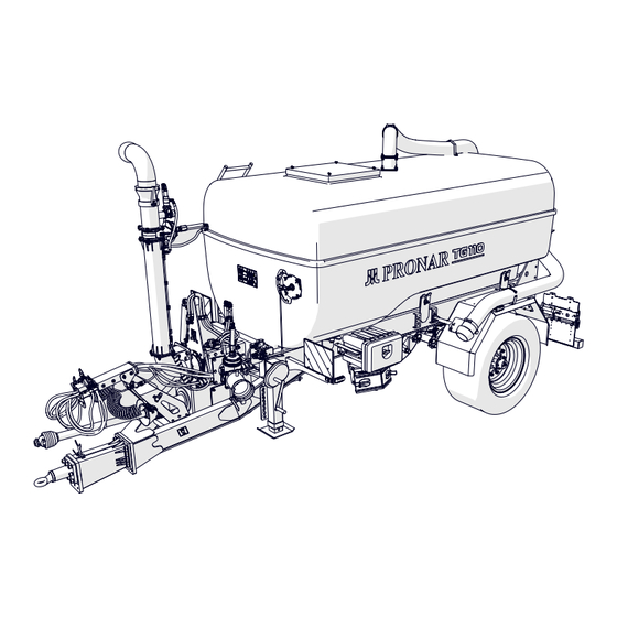
(4) wheel (5) drawbar (6) drawbar eye (7) parking stand (8) support wedges (9) lighting beam (10) mudguards (11) filling system (12) tool box (13) docking system (14) spreader (15) suction pipes (16) rear beam (17) ladder PRONAR TG110 649.01.UM.1A.EN... - Page 75 (11) driven by the tractor's power take-off shaft. The control is carried out using a remote control that performs individual functions of the liquid distribution system. The machine is coupled to the tractor by means of a drawbar (5) with a drawbar eye (6). BIZ.3.G-013.01.EN 649.01.UM.1A.EN PRONAR TG110...
-
Page 76: Pneumatic Braking System
(3), which adjusts the braking force of the machine to the weight of the transported load. The control valve has a button (2) that releases the brake, used when the trailer is disconnected from the PRONAR TG110 649.01.UM.1A.EN... - Page 77 Connection of wires Air reservoir Brake cylinder Control valve (connector) Air filter tractor. As soon as the air hose is connected to the tractor, the retarder device automatically adjusts itself to the position which enables the brakes to operate normally. 649.01.UM.1A.EN PRONAR TG110...
- Page 78 Chapter 4 - Construction and principle of operation 661-G.04-1 Figure 4.4 Control valve (1) control valve (2) release button BIZ.3.G-014.01.EN PRONAR TG110 649.01.UM.1A.EN...
-
Page 79: Parking Brake
(4). By turning the crank of the mech- anism (1) clockwise, the steel cable is tightened, causing the lever of the brake expanders to deflect, which, by spreading the brake shoes, immobilizes the machine. Before driving, release the parking brake - the steel cable must hang loosely. BIZ.3.G-004.01.EN 649.01.UM.1A.EN PRONAR TG110... - Page 80 Access to the vent line (3) and manholes (2) is provided by a ladder (5). On the front part there is a float indicator (4). CAUTION BIZ.3.G-005.11.EN After several trips with a load, check the tightness of screw connections (6). 4.10 PRONAR TG110 649.01.UM.1A.EN...
-
Page 81: Liquid Distribution System
A spreader (7) is installed in the rear part of the there are bystanders in the vicinity. Be vehicle. especially careful! 649.01.UM.1A.EN PRONAR TG110 4.11... -
Page 82: Hydraulic Liquid Distribution System
(6) and (7). The oil from the appropriate sections of with L-HL32 Lotos hydraulic oil. the distributor goes to the next actuators of the gate valves. In this way, the functions of loading, mixing and unloading of the transported medium are performed. 4.12 PRONAR TG110 649.01.UM.1A.EN... - Page 83 Chapter 4 - Construction and principle of operation BIZ.3.G-007.01.EN CAUTION Connect the hydraulic hoses first. Then start the remote control, in the last step turn on the tractor's PTO drive. 649.01.UM.1A.EN PRONAR TG110 4.13...
-
Page 84: Docking Mechanism
Changing of the working side of the machine consists in changing the position of the actuator (3) in relation to the mounting mast (2) and rotating the suction elbow (7). 4.14 PRONAR TG110 649.01.UM.1A.EN... -
Page 85: Hydraulic System Of The Docking Mechanism
(1) hydraulic conduits (2) hydraulic distributor (3) 6-way valve (4) docking latch actuator (5) suction latch actuator (6) tank latch actuator (7) docking mechanism vent actuator (8) cylinder lifting / lowering the docking mechanism tube (9) remote control 649.01.UM.1A.EN PRONAR TG110 4.15... - Page 86 Chapter 4 - Construction and principle of operation functions are performed by means of appropriate hy- draulic gate valves. The valve (3) switches the side suction to the docking mechanism. BIZ.3.G-008.01.EN 4.16 PRONAR TG110 649.01.UM.1A.EN...
- Page 87 Depressurize the system before con- sprinklers, etc. It is possible to place two hydraulic sections necting the hydraulic hoses. controlled from the agricultural tractor's external hydraulic manifold. BIZ.3.G-009.01.EN 649.01.UM.1A.EN PRONAR TG110 4.17...
-
Page 88: Electrical Lighting Installation
(5) rear combination lamp (6) rear marker lamp (7) license plate lamp (8) rear triangle reflector The electrical lightning installation of the machine is adapted to be supplied from a DC source with a voltage of 12V. 4.18 PRONAR TG110 649.01.UM.1A.EN... - Page 89 Before driving, check the operation and completeness of the electrical system. Driving with faulty lighting installation 5/58R 3/31 is forbidden. 7/58L 6/54 2/54 661-G.15.1 Figure 4.13 7 pin socket (1) socket (2) view from the beam side 649.01.UM.1A.EN PRONAR TG110 4.19...
- Page 90 Left indicator (yellow) 2/54 is can- Not used celled 3/31 is can- Ground (white) celled Left indicator (yellow) 5/58R Rear right position light (brown) 6/54 is can- STOP light (red) celled Left rear position lamp (black) BIZ.3.G-011.01.EN 4.20 PRONAR TG110 649.01.UM.1A.EN...
-
Page 91: Chapter 5 Control Panel
ChAPTER 5 CONTROL PANEL PRONAR TG110 649.01.UM.1A.EN... -
Page 92: Control System
Pay attention to the possibility of cut- a magnet, allowing easy access to the remote control ting or crushing the wiring harness buttons. at the point of entry of the cable by the elements of the cabin. PRONAR TG110 649.01.UM.1A.EN... -
Page 93: Main Control Pilot
Activate the appropriate section on the tractor's external hydraulic manifold, supplying the machine's hydraulic system. Press and hold the button (4) for 2 seconds (the LED flashes and turns on). Emptying Engage the PTO drive (pumping). After emptying the tank, press the STOP button (2) - the mixing diode will light up. Off the PTO drive. 649.01.UM.1A.EN PRONAR TG110... -
Page 94: Additional Remote Control
Main control pilot (1) power (2) STOP (mixing) (3) filling (4) emptying (5) lifting (6) lowering (7) additional lighting (8) housing 5.1.2 Additional remote control 661-X.05-1 Figure 5.3 Two-position distributor (A) side loading (2) loading docking mechanism (3) distributor PRONAR TG110 649.01.UM.1A.EN... -
Page 95: Inductive Sensors
The operation of the remote control is analogous to ue of 4 - 6mm. the main control device of the machine. 5.1.3 Inductive sensors 4 - 6 mm 661-X.06-1 Figure 5.5 Three-way valve position sensor (1) inductive sensor 649.01.UM.1A.EN PRONAR TG110... - Page 96 Chapter 5 - Construction and principle of operation The opening status of the three-way gate valve and 4 - 6 mm 661-X.04-1 Figure 5.6 Fill indicator sensor (1) inductive sensor the filling of the tank are monitored by inductive sensors. STR.3.G-001.01.EN PRONAR TG110 649.01.UM.1A.EN...
-
Page 97: Chapter 6 Rules Of Use
ChAPTER 6 RULES OF USE PRONAR TG110 649.01.UM.1A.EN... -
Page 98: Drawbar Height Adjusting
• Block the machine with the parking brake. • Place support wedges under the axle wheel. • Unfold the parking stand. • Dismantle the drawbar by unscrewing the screws (6). PRONAR TG110 649.01.UM.1A.EN... - Page 99 Danger of an accident. the cooperating elements (I), (II) and (III). • Position and install the drawbar eye properly. • Check the screw connections of the drawbar and the drawbar eye. OBS.3.G-011.01.EN 649.01.UM.1A.EN PRONAR TG110...
-
Page 100: Handling Of The Parking Stand
In position (B), the support foot (2) extends more slowly and you do not need to apply much force to raise the machine. Lifting up of the support • Remove the pin (5). • Move the crank (3) of the support from neutral PRONAR TG110 649.01.UM.1A.EN... - Page 101 (if the machine is to be hitched to a tractor). • Put on the safety pin (5), turn the crank to the neutral position (A). OBS.3.G-002.01.EN 649.01.UM.1A.EN PRONAR TG110...
-
Page 102: Connecting And Disconnecting Of The Machine
• Position the agricultural tractor directly in front of the drawbar eye. Drawbar height adjusting • Using the parking stand, set the appropriate height of the drawbar eye in relation to the hitch of the aggregated agricultural tractor. Follow the PRONAR TG110 649.01.UM.1A.EN... - Page 103 In this case, wait until the air in authorized access. the pneumatic system tank is replen- ished after starting the tractor and the Connecting of the braking system air compressor. • Connect the pneumatic system lines. 649.01.UM.1A.EN PRONAR TG110...
- Page 104 • Connect the hydraulic system quick couplers marked with red plug caps. • If necessary, connect the hydraulic system con- duits of the additional rear outputs, the corre- sponding pairs of which are marked with yellow and blue plug caps PRONAR TG110 649.01.UM.1A.EN...
- Page 105 Additional information • Make sure that they will not get entangled in moving parts of the tractor or machine during operation. Secure cables if necessary. • Perform daily inspection of the machine. 649.01.UM.1A.EN PRONAR TG110...
-
Page 106: Disconnecting The Trailer
• Disconnect all hoses one by one, securing connect the conduit marked red first, and only then the conduit marked yel- the ends by fitting plug caps to the hydraulic low. connections. 6.10 PRONAR TG110 649.01.UM.1A.EN... - Page 107 CAUTION • Release the drawbar eye, start the tractor and Always secure the uncoupled machine drive away with the tractor. against unauthorized use by attaching • Install the drawbar eye protection. the tie rod protection. OBS.3.G-012.01.EN 649.01.UM.1A.EN PRONAR TG110 6.11...
-
Page 108: Loading
Always check that the discharge line is open before starting the pump. 6.4.1 Loading via suction connection (left or right) Load the machine by performing the following steps: • Set the tractor with the machine to drive straight ahead on flat, stable and hard ground as close 6.12 PRONAR TG110 649.01.UM.1A.EN... - Page 109 • Disengage the tractor's PTO drive. may be released. • Open the valve (7) - position (A) - wait for Escaping gases are poisonous and a moment until the liquid column in the hose (3) explosive. drops to the tank, disassemble the hose and 649.01.UM.1A.EN PRONAR TG110 6.13...
-
Page 110: Loading Via Docking System (Left Or Right)
Loading via docking system (left or right) The additional equipment of the machine is a docking mechanism that you can use interchangeably with the side suction connector. • Set the tractor with the machine to drive straight ahead on flat, stable and hard ground at the place of loading. 6.14 PRONAR TG110 649.01.UM.1A.EN... - Page 111 (1) screw pump (2) suction connection (3) suction gate valve (4) tank gate valve (5) vent valve (6) remote control (7) filling indicator (8) hydraulic distributor (9) PTO shaft (A) side loading (B) loading docking mechanism 649.01.UM.1A.EN PRONAR TG110 6.15...
- Page 112 • Using the appropriate button on the remote control (6), raise the docking arm to the transport position. • Disengage the tractor's PTO drive. • Secure the rotation of the docking mechanism with the pin. OBS.3.G-004.01.EN 6.16 PRONAR TG110 649.01.UM.1A.EN...
-
Page 113: Transport
It is forbidden to park a loaded machine supported only by a parking stand. • The tractor operator is required to equip the machine with an attested or approved warning 649.01.UM.1A.EN PRONAR TG110 6.17... - Page 114 • Control the behaviour of the machine while driving on uneven terrain. Adjust speed to terrain and road conditions. • The machine is adapted for driving on slopes up to a maximum of 8°. 6.18 PRONAR TG110 649.01.UM.1A.EN...
- Page 115 Pro- Travel with a load through ruts, ditch- longed driving on slopes creates the risk of losing es, slopes, etc. poses a high risk of braking efficiency. overturning the machine. Be especial- ly careful. OBS.3.G-005.01.EN 649.01.UM.1A.EN PRONAR TG110 6.19...
-
Page 116: Unloading
• When the tank is empty, press the STOP button on the remote control. Suction valve closed Tank gate valve open STOP 661-H.09-1 Figure 5.11 Unloading system (1) spreader (2) three-way gate valve (3) remote control (4) drain valve (A) open position (B) closed position 6.20 PRONAR TG110 649.01.UM.1A.EN... - Page 117 Three-way valve - mixing • Disengage the tractor's PTO drive. CAUTION When using spraying devices when OBS.3.G-006.01.EN unloading, pay attention to whether there are any unauthorized persons in the unloading area. Watch out for overhead power lines. 649.01.UM.1A.EN PRONAR TG110 6.21...
-
Page 118: Feed Pump
Before Pure the pump using the suction port starting work, check if the drain valves (3) of the pump flap - see figure (5.8) are closed, the bottom flap (4) must be tightly closed. Any leakage of the pumping system disqualifies the machine from operation. OBS.3.G-007.01.EN 6.22 PRONAR TG110 649.01.UM.1A.EN... -
Page 119: Rules For The Use Of Tires
• Do not exceed the machine speed limit. • During the whole day cycle, take a minimum of one hour break at noon. • Observe 30 minutes breaks for cooling the tires after driving 75 km or after 150 minutes of 649.01.UM.1A.EN PRONAR TG110 6.23... - Page 120 Chapter 6 - Principles of use continuous driving, whichever comes first. • Avoid damaged surfaces, sudden and variable manoeuvres, and high speeds when turning. OBS.3.G-008.01.EN 6.24 PRONAR TG110 649.01.UM.1A.EN...
-
Page 121: Cleaning
• Fill the pump set with clean water, start the ma- chine in mixing mode. Empty the impurities from the pump chamber. • Clean suction lines, spreader and spreading equipment with pressurized water. 649.01.UM.1A.EN PRONAR TG110 6.25... - Page 122 • Observe environmental protection principles, wash trailer in designated places. • Washing and drying of the machine must take place at temperatures above 0 In winter, frozen water may cause damage to the pumping system and paint coating. OBS.3.G-009.01.EN 6.26 PRONAR TG110 649.01.UM.1A.EN...
-
Page 123: Storage
The tires do not deform and maintain the correct ge- ometry. You should also check your tire pressure from time to time, and if necessary inflate the wheels to the correct value. Store the articulated telescopic shaft for connecting to the tractor in a horizontal position. OBS.3.G-010.01.EN 649.01.UM.1A.EN PRONAR TG110 6.27... - Page 124 Chapter 6 - Principles of use 6.28 PRONAR TG110 649.01.UM.1A.EN...
- Page 125 ChAPTER 7 PERIODIC INSPECTIONS AND TEChNI- CAL MAINTENANCE PRONAR TG110 649.01.UM.1A.EN...
-
Page 126: General
Detailed information on the review schedule can be found in chapter entitled “Maintenance and inspection schedule". After the warranty expires, it is recommended that inspections be carried out by specialized repair workshops. During work, use protective clothing and protective equipment suitable for requirements. SER.3.B-001.01.EN PRONAR TG110 649.01.UM.1A.EN... -
Page 127: High-Risk Places
• Inform your co-workers about the planned work and the places where you will work. • Never work alone. One additional person should stay outside the high risk zone. Follow local labour laws. SER.3.G-002.01.EN 649.01.UM.1A.EN PRONAR TG110... -
Page 128: Maintenance And Inspection Schedule
3 months. Inspection carried out for a fee after the first 12 Warranty APSiO months of use of the machine, after reporting the owner. Inspection performed every 4 years of the machine Maintenance Service (1) - Authorized Sales and Service Point (2) - post-warranty service PRONAR TG110 649.01.UM.1A.EN... - Page 129 7.28 Kontrola instalacji hydraulicznej • 7.30 The pneumatic system inspection • 7.32 Smarowanie See table: Trailer lubrication schedule 7.46 See table: Schedule for tightening of Kontrola połączeń śrubowych 7.34 the critical bolted connections Replacement of hydraulic hoses • 7.38 649.01.UM.1A.EN PRONAR TG110...
- Page 130 Piston rod stroke in pneumatic and hydraulic sys- 25 - 45 mm tems Minimum brake lining thickness 5 mm An angle between the expander axis and the fork With the brake applied Parking brake Permissible clearance in the parking brake cable 150 mm SER.3.G-001.01.EN PRONAR TG110 649.01.UM.1A.EN...
-
Page 131: Trailer Preparation
• The jack must rest on a firm and stable surface. • The jack must be suited to the trailer’s carb weight. • In exceptional cases, release the parking brake of the machine, e.g. when measuring the play of axle bearings. In this case, be especially careful. 649.01.UM.1A.EN PRONAR TG110... - Page 132 Chapter 7 - Periodic inspections and the technical support 649-7.01-1 Figure 7.1 Recommended machine support points SER.3.G-020.01.EN PRONAR TG110 649.01.UM.1A.EN...
-
Page 133: Air Tank Drainage
• If it is necessary to clean the drain valve, follow the chapter “Cleaning the drain valve". Figure 7.2 Air tank (1) drain valve (2) air tank SER.3.8-004.01.EN 649.01.UM.1A.EN PRONAR TG110... -
Page 134: Guard Inspection
(3) and the mounting of the lamp shade covers (2). • Check that the caps (1) are secure and complete. • Check the mudguards (4) for correct mounting. • Tighten the screw connections of the cover fixings if necessary. SER.3.G-004.01.EN 7.10 PRONAR TG110 649.01.UM.1A.EN... -
Page 135: Checking Plugs And Connection Sockets
If the trailer is disconnected from the tractor, con- nections should be protected with covers or placed in their designated sockets. Before the winter period, 622-I.04-1 Figure 7.4 Checking the trailer connections 649.01.UM.1A.EN PRONAR TG110 7.11... - Page 136 (e.g. silicone lubri- cants for rubber elements). Each time before connecting the machine, check the technical condition and degree of cleanliness of connections and sockets on the agricultural tractor. If necessary clean or repair tractor sockets. SER.3.8-005.01.EN 7.12 PRONAR TG110 649.01.UM.1A.EN...
-
Page 137: Checking Of The Machine Before Driving
Clean the actuator if necessary. In winter, it may be necessary to defrost the actuator and remove the accumulated water through the blocked vents. If 65-6.16-1 Figure 7.5 Brake cylinder any damage is found, replace the actuator. When mounting the actuator, keep its original position 649.01.UM.1A.EN PRONAR TG110 7.13... - Page 138 While moving off, check the operation of the main brake system. For proper operation of the pneumatic system, an appropriate level of air pressure in the machine air tank is required. Check the correct operation of the other systems while operating the machine. SER.3.G-006.01.EN 7.14 PRONAR TG110 649.01.UM.1A.EN...
-
Page 139: Air Pressure Measurement, Tire And Rim Inspection
• Check the tread depth. • Check the side wall of the tire. • Inspect the tire for defects, cuts, deformations, bumps indicating mechanical damage to the tire. • Check that the tire is correctly positioned on the 649.01.UM.1A.EN PRONAR TG110 7.15... - Page 140 Rims should be checked for defor- mation, material cracks, weld cracks, corrosion, es- pecially around welds and in the place contact with the tire. SER.3.G-007.01.EN 7.16 PRONAR TG110 649.01.UM.1A.EN...
-
Page 141: Inspection And Cleaning Of The Delivery Pump
• If necessary, unscrew the oil filler plug (5) and oil contact with skin. add oil to the required level. Tighten the plug. The oil level should coincide with the lower edge of the inspection hole of the plug (7). • Tighten the plug (7). 649.01.UM.1A.EN PRONAR TG110 7.17... - Page 142 After 50 hours of pump operation, The oil level should coincide with the lower check and, if necessary, tighten all edge of the inspection hole of the plug (7). screw connections of the pump. • Tighten the plug (7). SER.3.G-008.01.EN 7.18 PRONAR TG110 649.01.UM.1A.EN...
-
Page 143: Cleaning The Air Filters
526-I.08-1 Figure 7.8 Air filter (1) filter (2) cover • The cartridge and the filter body should be thor- oughly washed and blowed out with compressed air. Installation should be made in reverse order. SER.3.8-008.01.EN 649.01.UM.1A.EN PRONAR TG110 7.19... -
Page 144: Cleaning The Drainage Valve
The pressure in the tank can be reduced by swinging the drain valve stem. • Unscrew the valve (1). • Clean the valve, blow with compressed air. • Replace the gasket. • Screw in the valve, fill the tank with air, check the tank for leaks. SER.3.8-012.01.EN 7.20 PRONAR TG110 649.01.UM.1A.EN... -
Page 145: Checking Brake Lining Wear
• Remove the upper and lower plugs and then check the thickness of the lining. • The brake shoes must be replaced if the thickness of the brake lining is less than 5 mm. • Check the the remaining linings for wear. SER.3.8-009.01.EN 649.01.UM.1A.EN PRONAR TG110 7.21... -
Page 146: Checking Of The Clearance Of The Axle Bearings
In this case, the bearing together with the sealing rings should be replaced or cleaned and re greased. When checking bearings, make sure that any noticeable looseness comes from the bearings, not the suspension system (e.g. 7.22 PRONAR TG110 649.01.UM.1A.EN... - Page 147 Chapter 7 - Periodic inspections and the technical support looseness on the spring pins, etc.). • Check the the technical condition of the hub cover, replace if necessary. SER.3.G-009.01.EN 649.01.UM.1A.EN PRONAR TG110 7.23...
-
Page 148: Checking Of Mechanical Brakes
The scope of activities • Measure the distance X with the tractor brake pedal released. • Measure the distance Y with the tractor brake pedal pressed. • Calculate the distance difference X-Y (rod stroke). 7.24 PRONAR TG110 649.01.UM.1A.EN... - Page 149 • Check the angle between the cylinder piston axis and the expander lever. • If the expander arm angle (2) and piston rod stroke exceed the range given in table 5.3, the brake should be adjusted. SER.3.8-011.11.EN 649.01.UM.1A.EN PRONAR TG110 7.25...
-
Page 150: Adjusting Of The Parking Brake Cable Tension
• Turn the parking brake crank (2) towards (B) and apply the parking brake. • Check the cable tension (1). • When the mechanism screw is completely re- moved, the cable should hang about 10 to 20 7.26 PRONAR TG110 649.01.UM.1A.EN... - Page 151 • Apply the parking brake and release it again. Check (approximately) cable slack. With the service and parking brakes fully released, the cable should hang about 10-20 mm. The axle spreader levers should be in the rest position. SER.3.G-010.01.EN 649.01.UM.1A.EN PRONAR TG110 7.27...
-
Page 152: Hydraulic System Checking
The tractor's and trailer’s hydraulic systems are sensitive to the presence of solid impurities that can cause damage to precise components of the installation (scratch the surface of cylinders, etc.) SER.3.8-015.01.EN 7.28 PRONAR TG110 649.01.UM.1A.EN... -
Page 153: The Pneumatic Braking System Inspection
Contact of pneumatic conduits, seals etc. with oil, grease, gasoline etc. may damage them or accelerate the aging process. Bisted, perma- nently deformed, cut or damaged wires should be re- placed for new ones. 649.01.UM.1A.EN PRONAR TG110 7.29... - Page 154 Chapter 7 - Periodic inspections and the technical support SER.3.G-019.01.EN DANGER Repair, replacement or regeneration of pneumatic system components may be performed only in a special- ized workshop. 7.30 PRONAR TG110 649.01.UM.1A.EN...
-
Page 155: Tightening Torques For Screw Connections
Replace the lost elements with new ones. 589-I.10-1 Figure 7.14 Screw with metric thread (1) strength class, (d) thread diameter 649.01.UM.1A.EN PRONAR TG110 7.31... - Page 156 M22x1 | M24x1.5 | M26x1.5 13 (1/2”) 50÷ 70 M26x1.5 | M27x1.5 | M27x2 16 (5/8”) 70÷ 100 M30x1.5 | M30x2 | M33x1.5 20 (3/4”) 70÷ 100 M38x1.5 | M36x2 25 (1”) 100÷ 150 M45x1.5 32 (1.1/4”) 150÷ 200 SER.3.G-011.01.EN 7.32 PRONAR TG110 649.01.UM.1A.EN...
-
Page 157: Tightening Road Wheels
Wheel nuts must not be tightened with impact wrenches, due to the danger of exceeding the permis- sible tightening torque, which may result in breaking the connection thread or breaking the hub pin. The wheels should be tightened according to the fol- lowing scheme: 649.01.UM.1A.EN PRONAR TG110 7.33... - Page 158 Chapter 7 - Periodic inspections and the technical support • after first use of the machine (one-time inspection), • every 2-3 hours of driving during the first month of use, • every 30 hours of driving. If the wheel was disassembled, the above steps should be repeated. SER.3.8-018.01.EN 7.34 PRONAR TG110 649.01.UM.1A.EN...
-
Page 159: Replacement Of Hydraulic Hoses
Chapter 7 - Periodic inspections and the technical support 7.21 REPLACEMENT OF hYDRAULIC hOSES • Rubber hydraulic hoses should be replaced every 4 years regardless of their technical con- dition. This operation should be entrusted to specialized workshops. SER.3.8-020.01.EN 649.01.UM.1A.EN PRONAR TG110 7.35... -
Page 160: Adjustment Of The Clearance Of Wheel Axle Bearings
(1) hub cover, (2) cotter pin, (3) nut, (4) tapered roller bearing The scope of activities Prepare the tractor and machine for adjustment as described in chapter „Preparing of the machine”. • Remove the hub cover (1). 7.36 PRONAR TG110 649.01.UM.1A.EN... - Page 161 Too strong pressure is not rec ommended due to the deterioration o bearings. • Secure the castellated nut with a cotter pin an mount the hub cover (1). • Gently tap the hub with a rubber or woode hammer. SER.3.G-013.01.E 649.01.UM.1A.EN PRONAR TG110 7.37...
-
Page 162: Brake Adjustment
(1) and the expander arm (3) should be approximately 90°. The machine wheels must brake simultaneously. The braking force also decreases when the angle of operation of the brake actuator piston rod (5) is not appropriate in relation to the expander arm (1). 7.38 PRONAR TG110 649.01.UM.1A.EN... - Page 163 (7). The mounting position depends on th type of braking system and the size of the tires use in the machine, it is selected by the Manufacturer an cannot be changed. 649.01.UM.1A.EN PRONAR TG110 7.39...
- Page 164 Each time when removing the pin or of the piston rod with the trailer brake off. the actuator, it is recommended to mark the place of the original fasten- • Press the brake pedal on the tractor, mark with ing. a line (B) the position of maximum extension of 7.40 PRONAR TG110 649.01.UM.1A.EN...
- Page 165 (pneumatic actuator). Check the correct mounting of the actuator. • Clean the cylinder, defrost if necessary and drain water through the unblocked ventilation holes 649.01.UM.1A.EN PRONAR TG110 7.41...
- Page 166 • Perform several brakes. Stop the machine and check the temperature of the brake drums. • If any drum is too hot, correct the brake ad- justment and perform the test drive again. SER.3.G-014.01.EN 7.42 PRONAR TG110 649.01.UM.1A.EN...
-
Page 167: Lubrication
Table 7.6. Lubricants Item Symbol Description General purpose machine grease (lithium, calcium), Solid grease for heavily loaded components with the addition of MoS graphite anticorrosive spray regular machine oil, silicone spray grease 649.01.UM.1A.EN PRONAR TG110 7.43... - Page 168 Chapter 7 - Periodic inspections and the technical support Table 7.7. Machine lubrication schedule Item Name Hub bearing (2 pieces in each hub) Expander shaft bushing Expander arm Parking brake mechanism (1) Parking brake roller pins (2) 649-7.02-1 Drawbar eye 649-7.02-1 7.44 PRONAR TG110 649.01.UM.1A.EN...
- Page 169 Chapter 7 - Periodic inspections and the technical support Item Name Parking stand 661-I.03-1 Three-way valve 661-I.05-1 Docking mechanism actuator bearings (1) Rotating joint of the docking mechanism 661-I.06-1 Fill indicator 649-7.04-1 SER.3.G-021.01.EN 649.01.UM.1A.EN PRONAR TG110 7.45...
- Page 170 Before travelling on a public road, make sure that the tractor diodes and in the event of damage, has a reflective warning triangle. they are replaced only as a complete lamp without the possibility of repair or SER.3.G-015.01.EN regeneration. 7.46 PRONAR TG110 649.01.UM.1A.EN...
-
Page 171: Consumables
In the event Table 7.8. Characteristics of the L-HL 32 oil Item Name Unit Viscosity classification according to ISO 3448VG Kinematic viscosity at 400 28.8 – 35.2 Quality classification according to ISO 6743/99 Quality classification according to DIN 51502 Flash-point 649.01.UM.1A.EN PRONAR TG110 7.47... - Page 172 Particularly important are safety rules and how to handle a given lubricant and how to dispose of waste (used containers, contam- inated rags, etc.). The information leaflet (product card) store together with the grease. SER.3.G-016.01.EN 7.48 PRONAR TG110 649.01.UM.1A.EN...
- Page 173 Disc wheel size tires 560/60- R22,5 161D 172A8 16.00x22,5; ET=+10 400kPa 600/55- R26,5 165D 176A8 20.00x26,5; ET=0 400kPa 650/55- R26,5 169D 20.00x26,5; ET=0 400kPa 650/65- R30,5 176D 20.00x30,5; ET=+35 400kPa 710/50- R30,5 173D 24.00x30,5; ET=0 400kPa 28L26 173A8 ET=0 400kPa SER.3.G-017.01.EN 649.01.UM.1A.EN PRONAR TG110 7.49...
- Page 174 Worn brake linings. Replace the brake shoes. Check the oil quality make sure that the Incorrect hydraulic Incorrect hydraulic oil vis- oils in both machines are of the same system operation. cosity. grade. If necessary, change the oil in the trailer tractor and/or 7.50 PRONAR TG110 649.01.UM.1A.EN...
- Page 175 Air pressure too high. for proper inflation regularly. centre section. Excessive one-sid- Incorrect convergence. ed wear of the left Damaged spring leaf on one side of the Driving axles incorrectly or right shoulder suspension. Replace the springs. adjusted. tire. 649.01.UM.1A.EN PRONAR TG110 7.51...
- Page 176 Replace impeller and impeller housing The pump makes Worn joints Replace the joints noise Cavitation due to too high Reduce the revs revolutions or too small a Increase the diameter of the suction pipe diameter of the suction line SER.3.G-018.01.EN 7.52 PRONAR TG110 649.01.UM.1A.EN...
-
Page 177: Pronar Tg110
ATTAChMENTS PRONAR TG110 649.01.UM.1A.PL...
Need help?
Do you have a question about the TG110 and is the answer not in the manual?
Questions and answers