Table of Contents
Advertisement
Quick Links
TRANSLATION OF THE ORIGINAL COPY OF THE MANUAL
EDITION 4B-11-2013
PRONAR Sp. z o.o.
17-210 NAREW, UL. MICKIEWICZA 101A, PODLASKIE PROVINCE
phone:
fax:
OPERATOR`S MANUAL
AGRICULTURAL TRAILER
PRONAR T900
+48 085 681 63 29
+48 085 681 63 81
+48 085 681 63 83
PUBLICATION NO. 182N-00000000-UM
+48 085 681 64 29
+48 085 681 63 82
+48 085 682 71 10
www.pronar.pl
Advertisement
Table of Contents

Related Manuals for PRONAR T900


Summary of Contents for PRONAR T900
- Page 1 PRONAR Sp. z o.o. 17-210 NAREW, UL. MICKIEWICZA 101A, PODLASKIE PROVINCE phone: +48 085 681 63 29 +48 085 681 64 29 +48 085 681 63 81 +48 085 681 63 82 fax: +48 085 681 63 83 +48 085 682 71 10 www.pronar.pl...
- Page 3 The machine is designed to meet obligatory standards, documents and legal regulations currently in force. The manual describes the basic safety rules and operation of agricultural trailer Pronar T900. If the information contained in the Operator's Manual needs clarification then the user should refer for assistance to the sale point where the machine was purchased or to the Manufacturer.
- Page 4 SYMBOLS APPEARING IN THIS OPERATOR'S MANUAL Information, descriptions of danger and precautions and also recommendations and prohibitions associated with user safety instructions are marked: and also preceded by the word "DANGER”. Failure to observe the instructions may endanger the machine operator's or other person's health or life. Particularly important information and instructions, the observance of which is essential, are distinguished in the text by the sign: and also preceded by the word "ATTENTION".
- Page 5 DIRECTIONS USED IN THIS OPERATOR'S MANUAL Left side – side to the left hand of the operator facing in the direction of machine's forward travel. Right side – side to the right hand of the operator facing in the direction of machine's forward travel.
-
Page 7: Table Of Contents
CONTENTS 1 BASIC INFORMATION IDENTIFICATION 1.1.1 TRAILER IDENTIFICATION 1.1.2 AXLE IDENTIFICATION 1.1.3 LIST OF FACTORY NUMBERS PROPER USE EQUIPMENT WARRANTY TERMS TRANSPORT 1.10 1.5.1 TRANSPORT ON VEHICLE 1.10 1.5.2 INDEPENDENT TRANSPORT BY THE USER. 1.12 ENVIRONMENTAL HAZARDS 1.13 WITHDRAWAL FROM USE 1.14 2 SAFETY ADVICE BASIC SAFETY RULES... - Page 8 3 DESIGN AND OPERATION TECHNICAL SPECIFICATION TRAILER CONSTRUCTION 3.2.1 CHASSIS 3.2.2 LOAD BOX 3.2.3 SUSPENSION HYDRAULIC SYSTEM 3.2.4 HYDRAULIC MECHANISM OF SLIDING WALL 3.2.5 TAILGATE HYDRAULIC SYSTEM 3.12 3.2.6 HYDRAULIC STEERING SYSTEM 3.14 3.2.7 HYDRAULIC SYSTEM OF THE HINGED WALL 3.16 3.2.8 BRAKING SYSTEM 3.17...
- Page 9 PROPER USE AND MAINTENANCE OF TYRES 4.26 5 MAINTENANCE PRELIMINARY INFORMATION MAINTENANCE OF WHEEL AXLE 5.2.1 PRELIMINARY INFORMATION 5.2.2 CHECKING WHEEL AXLE BEARINGS FOR SLACKNESS 5.2.3 ADJUSTMENT OF AXLE BEARING SLACKNESS 5.2.4 MOUNTING AND DISMOUNTING WHEEL, INSPECTION OF WHEEL NUT TIGHTENING 5.2.5 CHECKING AIR PRESSURE IN TYRES, EVALUATING TECHNICAL CONDITION OF TYRES AND STEEL WHEELS 5.2.6 CHECKING THICKNESS OF BRAKE SHOE LININGS...
- Page 10 MAINTENANCE OF ELECTRICAL SYSTEM AND WARNING ELEMENTS 5.28 5.7.1 PRELIMINARY INFORMATION 5.28 5.7.2 REPLACEMENT OF BULBS 5.29 TRAILER LUBRICATION 5.29 CONSUMABLES 5.35 5.9.1 HYDRAULIC OIL 5.35 5.9.2 LUBRICANTS 5.36 5.10 ADJUSTMENT OF LIMIT VALVES 5.37 5.11 CLEANING THE TRAILER 5.39 5.12 STORAGE 5.40 5.13 TIGHTENING TORQUE FOR NUT AND BOLT...
- Page 11 SECTION BASIC INFORMATION...
-
Page 12: Identification
Pronar T900 SECTION 1 1.1 IDENTIFICATION 1.1.1 TRAILER IDENTIFICATION FIGURE 1.1 Location of the data plate and serial number (1) data plate, (2) serial number The trailer is marked with a data a plate (1) and a serial number (2). The serial number and data plate are located on the front beam of the longitudinal member of the lower frame –... -
Page 13: Axle Identification
SECTION 1 Pronar T900 TABLE 1.1 Markings on data plate ITEM MARKING General description and purpose Symbol / type of trailer Year of manufacture Seventeen digit serial number (VIN) Official certificate number Tare weight Maximum gross weight Carrying capacity Permissible hitching system loading... -
Page 14: List Of Factory Numbers
Pronar T900 SECTION 1 FIGURE 1.2 Location of the axle data plate (1) axle, (2) data plate 1.1.3 LIST OF FACTORY NUMBERS In the event of ordering a replacement part or in the case of the appearance of problems it is often essential to give the factory numbers of parts or the VIN number of the trailer, therefore it is recommended that these numbers are inscribed in the spaces below. -
Page 15: Proper Use
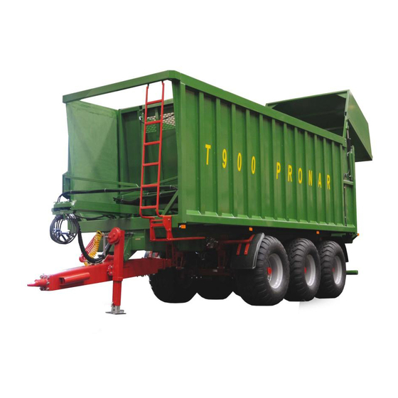
Pronar T900 1.2 PROPER USE T900 movable wall trailer is designed for transport of harvested crops and agricultural products as well as loose and bulk materials at the farm and on public roads at a maximum speed of 40 km/h. - Page 16 Pronar T900 SECTION 1 must be observed. The trailer speed must not, however, be greater than the maximum design speed. Using it as intended also involves all actions connected with the safe and proper operation and maintenance of the machine. Due to the above, the user is obliged to: •...
-
Page 17: Equipment
SECTION 1 Pronar T900 TABLE 1.2 Requirements for agricultural tractor CONTENTS UNIT REQUIREMENTS Brake system - sockets Double conduit pneumatic system according to ISO 1728 Hydraulic system according to ISO 7421-1 Maximum system pressure Double conduit pneumatic system bar / kPa 6.5 / 650... - Page 18 Pronar T900 SECTION 1 TABLE 1.3 Trailer's equipment EQUIPMENT • The Operator's Manual • Warranty Book • Connection lead for the electrical system • Double conduit pneumatic system • Double conduit pneumatic system with ALB • Double conduit pneumatic system with ALB (hydraulic) •...
-
Page 19: Warranty Terms
Pronar T900 1.4 WARRANTY TERMS PRONAR Sp. z o.o., Narew guarantees the reliable operation of the machine when it is used according to its intended purpose as described in the OPERATOR'S MANUAL. The repair period is specified in the WARRANTY BOOK. -
Page 20: Transport
Pronar T900 SECTION 1 For detailed Terms & Conditions of Warranty, please refer to the WARRANTY BOOK attached to each newly purchased machine. Demand that the seller carefully and precisely fills out the Warranty Book and warranty repair coupons. A missing date of purchase or sale point stamp may make the user ineligible for any warranty repair or refund. - Page 21 SECTION 1 Pronar T900 unsuitable for use. Carefully read the information stated in the Operator's Manual for the given securing measure. Chocks, wooden blocks or other objects without sharp edges should be placed under the wheels of the trailer to prevent it from rolling. Trailer wheel blocks must be nailed to the low platform planks of the vehicle or secured in another manner preventing their movement.
-
Page 22: Independent Transport By The User
Pronar T900 SECTION 1 FIGURE 1.3 Positioning of transport lugs (1) transport lug, (2) longitudinal member of lower frame, (3) transport decal 1.5.2 INDEPENDENT TRANSPORT BY THE USER. In the event of independent transport by the user after purchase of the trailer, the user must read the trailer Operator's Manual and adhere to the recommendations contained therein. -
Page 23: Environmental Hazards
SECTION 1 Pronar T900 1.6 ENVIRONMENTAL HAZARDS A hydraulic oil leak constitutes a direct threat to the natural environment owing to its limited biodegradability. The negligible solubility of hydraulic oil in water does not cause extreme toxicity of organisms living in the aquatic environment. The formation of a film of oil on the water may be the direct cause of physical action on organism, perhaps causing change of oxygen values in the water because of lack of direct contact of air with the water. -
Page 24: Withdrawal From Use
Pronar T900 SECTION 1 1.7 WITHDRAWAL FROM USE In the event of decision by the user to withdraw the trailer from use, comply with the regulations in force in the given country concerning withdrawal from use and recycling of machines withdrawn from use. Before commencing dismantling, totally remove the oil from the hydraulic system and reduce air pressure completely in the pneumatic braking system (e.g. -
Page 25: Safety Advice
SECTION SAFETY ADVICE... -
Page 26: Basic Safety Rules
Pronar T900 SECTION 2 2.1 BASIC SAFETY RULES 2.1.1 USE OF TRAILER • Before using the machine, the user must carefully read this Operator's Manual and the Warranty Book. When operating the machine, the operator must comply with all recommendations contained in the Operator's Manual. -
Page 27: Hitching And Unhitching From Tractor
SECTION 2 Pronar T900 • Any modification to the trailer frees the manufacturer from any responsibility for damage or detriment to health, which may arise as a result. 2.1.2 HITCHING AND UNHITCHING FROM TRACTOR • Do NOT hitch the trailer to tractor if the tractor does not fulfil the requirements specified by the Manufacturer (minimum tractor power demand, wrong hitch, etc.) -
Page 28: Hydraulic And Pneumatic Systems
Pronar T900 SECTION 2 • Do NOT unhitch the trailer from the tractor when the tailgate and the sliding wall are raised. Exercise caution when disconnecting trailer. 2.1.3 HYDRAULIC AND PNEUMATIC SYSTEMS • When operating, the hydraulic and pneumatic systems are under high pressure. -
Page 29: Loading And Unloading
SECTION 2 Pronar T900 2.1.4 LOADING AND UNLOADING • Loading and unloading work should be carried out by persons experienced in this type of work. • Unloading and loading of trailer may only take place when the machine is positioned on level and hard surface and connected to tractor. Tractor and trailer must be placed to drive forwards. -
Page 30: Transporting The Machine
Pronar T900 SECTION 2 • Do NOT slide the trailer's wall to unload when the tailgate is closed. • Keep a safe distance from electric power lines when rising the tailgate. • After completed unloading, ensure that the load box is empty. - Page 31 SECTION 2 Pronar T900 • Chocks (1) should be placed only under one wheel (one in front of the wheel, the other behind the wheel - figure (2.1)). • Do NOT raise the front axle when the trailer is loaded.
- Page 32 Pronar T900 SECTION 2 • During reversing one should use the assistance of another person. During manoeuvring the person helping must stay at a safe distance from the danger zone and be visible all the time to the tractor driver.
-
Page 33: Tyres
SECTION 2 Pronar T900 • Please note that the braking distance of the tractor and trailer combination is substantially increased at higher speeds and loads. 2.1.6 TYRES • When working with tyres, the trailer should be immobilised with parking brake and secured against rolling by placing chocks under wheel. - Page 34 Pronar T900 SECTION 2 • The trailer may only be stood on when the machine is absolutely motionless, the tractor engine is switched off and the ignition key removed from the ignition. Tractor and trailer should be immobilized with parking brake and chocks should be placed under the trailer wheels.
-
Page 35: Residual Risk
Damaged drawbar eye should be replaced. 2.2 RESIDUAL RISK Pronar Sp. z o. o. in Narew has made every effort to eliminate the risk of accidents. There is, however, a certain residual risk, which could lead to an accident, and this is connected mainly with the actions described below: •... -
Page 36: Information And Warning Decals
In the event of their destruction, they must be replaced with new ones. Safety decals are available from your PRONAR dealer or directly from PRONAR customer service. New assemblies, changed during repair, must be labelled once again with the appropriate safety signs. - Page 37 SECTION 2 Pronar T900 TABLE 2.1 Information and warning decals SAFETY SYMBOL DESCRIPTION Type of trailer Before starting work, carefully read THE OPERATOR'S MANUAL Before servicing activities or repairs, turn off engine and remove key from ignition Check the condition of the screw and...
- Page 38 Pronar T900 SECTION 2 SAFETY SYMBOL DESCRIPTION Raising / lowering the tailgate Plug cap - black Front wall sliding Plug cap - blue Opening/closing the side wall extension. Plug cap (green) Rising/lowering the right and the left side of the trailer...
- Page 39 SECTION 2 Pronar T900 SAFETY SYMBOL DESCRIPTION Fixing points for the transport Rising/lowering the first wheel axle Plug cap - red – pressure value should be adapted to tyres, - shown in figure (1.2), - glued to hydraulic conduit. Numbers in the Item column correspond to labels in figure (2.3)
- Page 40 Pronar T900 SECTION 2 FIGURE 2.3 Decal locations 2.16...
-
Page 41: Design And Operation
SECTION DESIGN AND OPERATION... -
Page 42: Technical Specification
Pronar T900 SECTION 3 3.1 TECHNICAL SPECIFICATION TABLE 3.1 Basic technical date of the standard version CONTENTS UNIT T900 Trailer dimensions Total length 10 510 Total width 2 595 Height 3 543 Internal load box dimensions Length 8 320 Width... -
Page 43: Trailer Construction
3.2 TRAILER CONSTRUCTION 3.2.1 CHASSIS Two versions of T900 trailer chassis are available: with triple axle mechanical suspension (3.1), and with triple axle hydraulic suspension (3.2). The chassis consists of subassemblies shown in figures (3.1) and (3.2). Lower frame (1) of the trailer is a structure welded from steel sections. - Page 44 Pronar T900 SECTION 3 FIGURE 3.1 Chassis with mechanical suspension (1) lower frame, (2) front steering axle, (3) middle rigid axle, (4) rear steering axle, (5) adjustment bolt, (6) suspension spring, (7) rigid suspension string, (8) hydraulic pump box...
- Page 45 SECTION 3 Pronar T900 FIGURE 3.2 Chassis with hydraulic suspension (1) lower frame, (2) front steering axle, (3) middle rigid axle, (4) rear steering axle, (5) hydraulic cylinder, (6) parabolic arm, (7) hydraulic pump box, (8) parabolic arm bracket...
-
Page 46: Load Box
(7) is attached to the drawbar side. At the front of the load box, there is a ladder (8). The sliding wall (5) is used for unloading the T900 trailer load box. The sliding wall is equipped with elastomeric seals that ensure tightness between the wall and the load box sides. - Page 47 SECTION 3 Pronar T900 FIGURE 3.3 Load box (1) load box, (2) hinged wall extension, (3) tailgate, (4) fender, (5) sliding wall, (6) drawbar, (7) drawbar support, (8) ladder, (9) mudguards...
-
Page 48: Suspension Hydraulic System
Pronar T900 SECTION 3 3.2.3 SUSPENSION HYDRAULIC SYSTEM The hydraulic system of the suspension is supplied with hydraulic oil from the tractor's external hydraulic system. The hydraulic system filling is performed only when hitching the trailer to the tractor for the first time - see section (4.3.2) "SETTING THE HYDRAULIC SUSPENSION". -
Page 49: Hydraulic Mechanism Of Sliding Wall
SECTION 3 Pronar T900 quick couplers (1), (2), (3) and marked with red plugs. Valves (4) and connection conduits are used for setting and adjusting the trailer suspension - section (4.3.2). After connecting to the hydraulic connection, the conduit marked with label (7) is used for rising the front axle. - Page 50 Pronar T900 SECTION 3 FIGURE 3.6 Arrangement of sliding wall elements (1) sliding wall, (2) cylinder carriage, (3) telescopic cylinder, (4) wall sliding cylinder, (5) wall rising cylinder, (6) connecting arm, (7) limit valve I, (8) limit valve II 3.10...
- Page 51 SECTION 3 Pronar T900 The sliding wall mechanism makes it possible to compact the material during loading. This is particularly important when harvesting green fodder because silage is compacted by the trailer's sliding wall. The design of the sliding wall mechanism and the arrangement of the system components are shown in figure (3.6).
-
Page 52: Tailgate Hydraulic System
Pronar T900 SECTION 3 FIGURE 3.7 The diagram of the hydraulic system of the front sliding wall (1) quick coupler - plug, (2) hydraulic cylinder I, (3) telescopic cylinder, (4) limit valve I, (5) hydraulic cylinder II, (6) limit valve I, (7) flow divider 3.2.5 TAILGATE HYDRAULIC SYSTEM... - Page 53 SECTION 3 Pronar T900 FIGURE 3.8 Design and diagram of the tailgate hydraulic system (1) tailgate, (2) hydraulic cylinder, (3) quick coupler - plug, (4) hydraulic lock 3.13...
-
Page 54: Hydraulic Steering System
SECTION 3 3.2.6 HYDRAULIC STEERING SYSTEM As standard, Pronar T900 trailer is equipped with hydraulic steering system for controlling the wheels of the first axle and the third axle of the trailer. Two external axles (1) and (2) are steering axles. They are equipped with cylinder (3) that is connected through hydraulic conduits and pipes with double-acting hydraulic cylinders (4) located on both sides of the drawbar, forming a closed circuit. - Page 55 SECTION 3 Pronar T900 turning the trailer's wheels. Hydraulic accumulators (7) are used in order to eliminate minimal swing of axle steering cylinders and reduce load applied to the system when manoeuvring (7). Under the load box, on the left side, there is a hydraulic hand pump (8) for filling and setting the pressure in the steering system –...
-
Page 56: Hydraulic System Of The Hinged Wall
3.2.7 HYDRAULIC SYSTEM OF THE HINGED WALL Standard version of Pronar T900 trailer is equipped with the load box with two fixed side walls. Three optional versions of the load box are also available: with the left hinged wall, with the right hinged wall or with both hinged walls. -
Page 57: Braking System
(3) sequence valve (opening the side gate), (4) sequence valve (clamp locking), (5) hydraulic lock, (6) quick coupler - plug, (7) gland 3.2.8 BRAKING SYSTEM Depending on the version, T900 trailer is equipped with one of the four types of main brake system: • double conduit pneumatic system with manual regulator, •... - Page 58 Pronar T900 SECTION 3 trailer and the tractor, the control valve will automatically activate trailer's brakes. When the conduit is connected to the tractor's connection, the system automatically changes its position to allow normal brake operation. FIGURE 3.13 Three-step braking force regulator...
- Page 59 SECTION 3 Pronar T900 FIGURE 3.14 Diagram of double conduit pneumatic system with manual regulator (1) control conduit connection with a filter (yellow), (2) supply conduit connection with a filter (red), (3) releasing-parking valve, (4) brake valve without brake release, (5) manual braking...
- Page 60 Pronar T900 SECTION 3 FIGURE 3.15 Diagram of pneumatic system with ALB mechanical regulator (1) control conduit connection with a filter (yellow), (2) supply conduit connection with a filter (red), (3) loosening-parking valve, (4) brake valve without brake release, (5) ALB mechanical...
- Page 61 SECTION 3 Pronar T900 FIGURE 3.16 Diagram of pneumatic system with ALB hydraulic regulator (1) control conduit connection with a filter (yellow), (2) supply conduit connection with a filter (red), (3) loosening-parking valve, (4) brake valve without brake release, (5) ALB hydraulic...
- Page 62 Pronar T900 SECTION 3 FIGURE 3.17 Design and diagram of the hydraulic braking system (1) hydraulic cylinder, (2) hydraulic quick coupler The main hydraulic brake (available as optional equipment) is activated from the tractor driver's cab by depressing the brake pedal. Agricultural tractor equipped with suitable hydraulic system is required to operate the hydraulic braking system.
-
Page 63: Pneumatic Parking Brake
SECTION 3 Pronar T900 3.2.9 PNEUMATIC PARKING BRAKE The parking brake is used for immobilising trailer while standing motionless. The parking brake is activated by loosening-parking valve (1) – figure (3.18). Two push-buttons located in this valve make it possible to set the trailer to an appropriate working mode. Black push- button (2) controls the loosening valve, that is designed for releasing or engaging the brake if the trailer is unhitched from the tractor. -
Page 64: Electrical Lighting System
Pronar T900 SECTION 3 3.2.10 ELECTRICAL LIGHTING SYSTEM The trailer's electrical system is designed for supply from a direct current source of 12 V. Connection of the trailer electrical system with the tractor should be made using an appropriate connection lead delivered with the trailer. - Page 65 SECTION 3 Pronar T900 FIGURE 3.20 Electric lighting system diagram (1) central wiring harness, (2) front wiring harness, (3) rear wiring harness 3.25...
- Page 66 Pronar T900 SECTION 3 TABLE 3.2 List of electrical component markings SYMBOL NAME Rear right lamp assembly Rear left lamp assembly Front seven pin socket Rear seven pin socket Right license plate light Left license plate light Front right parking light...
- Page 67 SECTION 3 Pronar T900 TABLE 3.4 Lead colour marking MARKING COLOUR White Black Blue Orange Green Black and green 3.27...
- Page 68 Pronar T900 SECTION 3 3.28...
-
Page 69: Correct Use
SECTION CORRECT USE... -
Page 70: Preparing For Work Before The First Use
Pronar T900 SECTION 4 4.1 PREPARING FOR WORK BEFORE THE FIRST USE 4.1.1 CHECKING THE TRAILER AFTER DELIVERY The manufacturer guarantees that the trailer is fully operational and has been checked according to quality control procedures and is ready for normal use. This does not release the user from an obligation to check the machine's condition after delivery and before first use. -
Page 71: Preparing The Trailer For The First Hitching To
SECTION 4 Pronar T900 4.1.2 PREPARING THE TRAILER FOR THE FIRST HITCHING TO TRACTOR Preparation Ensure that the hitch, pneumatic, hydraulic and electric connections in the tractor are according to the requirements; otherwise, the trailer should not be hitched to the tractor. - Page 72 Pronar T900 SECTION 4 control of the front axle rising (hydraulic suspension system), when moving off, check if the main brakes operate correctly, when driving, check operation of the wheel turning system, check if the parking brake of the trailer operates correctly, ensure that the pneumatic system does not have any leaks.
-
Page 73: Technical Inspection Of The Trailer
SECTION 4 Pronar T900 4.2 TECHNICAL INSPECTION OF THE TRAILER When preparing the trailer for normal use, check individual elements according to guidelines presented in table (4.1). TABLE 4.1 Technical inspection schedule DESCRIPTION MAINTENANCE ACTIVITIES FREQUENCY Attach trailer to the tractor and test the Operation of brake system brakes after moving off. -
Page 74: Hitching And Unhitching The Trailer
(the tractor hitch system diagram is shown in figure (4.3). The tractor should have at least three hydraulic sections. The first hitching of T900 trailer to a given tractor should be performed according to the description in subsections (4.3.1) - (4.3.4). - Page 75 SECTION 4 Pronar T900 In order to hitch the trailer to the tractor, perform the actions below in the sequence presented. Machine must be immobilised by parking brake. Hitching to tractor Position the agricultural tractor in front of the trailer's drawbar eye.
- Page 76 Pronar T900 SECTION 4 Connect the hydraulic conduits of the sliding wall (marked blue). Connect the hydraulic conduits of the side hinged wall marked green (option). When connecting double-conduit braking system conduits, first connect the yellow conduit to yellow socket in the tractor and only then connect the red conduit to the red socket in the tractor.
-
Page 77: Trailer Support Operation
SECTION 4 Pronar T900 Disconnect hydraulic brake system conduit (applies to trailer version with hydraulic brake system). Protect conduit ends with covers. Place conduit plugs in appropriate conduit hanger sockets. Unlock and disconnect the drawbar hitching eye and disconnect the steering system control strings from the tractor hitch and drive the tractor away. -
Page 78: Setting The Hydraulic Suspension
Pronar T900 SECTION 4 Turn the crank in proper direction in order to lower the support to the ground or adjust the drawbar eye height in relation to the hitch (if the trailer is to be hitched to tractor) FIGURE 4.1... - Page 79 SECTION 4 Pronar T900 connect the hydraulic conduit for front axle rising (marked with the label) (item 13 - table 2.1) to the drain connector in the tractor, so called "free drain", connect the two remaining supply conduits marked with red plugs to two...
-
Page 80: The First Adjustment Of The Drawbar Height
Pronar T900 SECTION 4 ATTENTION To ensure correct operation of the trailer's suspension, the hydraulic cylinder rods in unloaded trailer should be extended to half the length of the stroke (100mm). The trailer must not be used when the hydraulic cylinders are set in the extreme positions. -
Page 81: Setting The Wheel Steering System
4.3.4 SETTING THE WHEEL STEERING SYSTEM Pronar T900 trailer with the hydraulic steering system should be hitched using suitable and certified tractor hitches equipped with two additional ball hitches (or attachments) with a ball diameter of Ø50 arranged according to the tractor hitch system diagram –... - Page 82 Pronar T900 SECTION 4 FIGURE 4.3 Connecting the trailer steering system with the tractor (1) drawbar, (2) drawbar hitching eye, (3) string, (4) limiter, (5) mechanical support, (6) ball hitch with a ball diameter of Ø80, (7) ball hitch for connecting the steering system with a ball diameter of Ø50, (8) drawbar cylinder, (A) the tractor hitch system diagram meeting the...
- Page 83 SECTION 4 Pronar T900 close all valves (3) and set the pump lever (2) aside, drive the tractor with the trailer attached and check correctness of the system operation. If the system malfunctions during the trailer use, perform the above adjustments.
-
Page 84: Operation Of Pneumatic Parking Brake
Pronar T900 SECTION 4 4.4 OPERATION OF PNEUMATIC PARKING BRAKE TABLE 4.2 Operation of the T900 trailer's parking brake TRAILER LOOSENING PARKING CONNECTED WITH VALVE VALVE WORKING PARKING TRACTOR BY (BLACK (RED PUSH- CONDITIONS BRAKE MEANS OF PUSH- BUTTON) PNEUMATIC... - Page 85 SECTION 4 Pronar T900 because the trailer may be damaged. Loading of materials other than those recommended by the Manufacturer is forbidden. ATTENTION Do NOT exceed the permissible load weight of trailer because this may cause danger to road traffic and cause damage to the machine.
- Page 86 Pronar T900 SECTION 4 WEIGHT BY VOLUME TYPE OF MATERIAL kg/m Building materials: cement 1 200 – 1 300 dry sand 1 350 – 1 650 wet sand 1 700 – 2 050 solid bricks 1 500 – 2 100 hollow bricks 1 000 –...
- Page 87 SECTION 4 Pronar T900 WEIGHT BY VOLUME TYPE OF MATERIAL kg/m Seeds and grains: beans 750 - 850 mustard 600 - 700 peas 650 - 750 lentils 750 - 860 runner beans 780 - 870 barley 600 - 750 clover...
- Page 88 Pronar T900 SECTION 4 Bulk materials Loading bulk materials is normally conducted with the use of loaders or conveyors and possibly loading manually. Do not load bulk materials to a height greater than that of side walls or extensions. On completion of loading, the load should be evenly spread over the whole surface of the load box.
- Page 89 SECTION 4 Pronar T900 Loads in packaging Loads transported in packaging (boxes, sacks) must be laid closely side-by-side beginning from the front side of the trailer. If it is essential to lay several layers, particular groups should be stacked alternately (in block system). The load must be laid tightly together and on the whole surface of the trailer floor.
-
Page 90: Transporting The Machine
Pronar T900 SECTION 4 4.6 TRANSPORTING THE MACHINE When driving on roads, respect the road traffic regulations, exercise caution and prudence. Listed below are the key guidelines for driving the tractor and trailer combination. • Before moving off, make sure that there are no bystanders, especially children, near the trailer or the tractor. - Page 91 SECTION 4 Pronar T900 • When driving, comply with all road traffic regulations, indicate an intention to turn using indicator lamps, keep all road lights and indicator lights clean at all times and ensure they are in good condition. Any damaged or lost lamps or indicator lights must be immediately repaired or replaced.
-
Page 92: Unloading
SECTION 4 4.7 UNLOADING Unloading of the T900 trailer's load box is performed by means of the front sliding wall mechanism. The hydraulic mechanism of the sliding wall is used for automatic unloading of the trailer by pushing the load to the rear. This system enables unloading in difficult atmospheric or spatial conditions, for example in low ceiling buildings, on steep slopes or in strong wind. - Page 93 SECTION 4 Pronar T900 FIGURE 4.5 Unloading the load box (1) load box, (2) sliding wall, (3) tailgate The load box tailgate is equipped with the grain chute – figure (4.6) for unloading loose materials. The width of the grain chute (1) opening can be adjusted by means of lever (2).
-
Page 94: Proper Use And Maintenance Of Tyres
Pronar T900 SECTION 4 FIGURE 4.6 Grain chute (1) grain chute, (2) lever, (3) locking screw 4.8 PROPER USE AND MAINTENANCE OF TYRES • When working on the tyres, chocks or other objects without sharp edges should be placed under the wheels of the trailer to prevent it from rolling. Wheels can be taken off the trailer axle only when the trailer is not loaded. - Page 95 SECTION 4 Pronar T900 • Air pressure in tyres should be also checked during the whole day of intensive work. Please note that higher temperatures could raise tyre pressure by as much as 1 bar. At high temperatures and pressure, reduce load or speed.
- Page 96 Pronar T900 SECTION 4 4.28...
-
Page 97: Maintenance
SECTION MAINTENANCE... -
Page 98: Preliminary Information
Pronar T900 SECTION 5 5.1 PRELIMINARY INFORMATION When using the trailer, regular inspections of its technical condition are essential and the performance of maintenance procedures, which keep the machine in good technical condition. In connection with this the user of the trailer is obliged to perform all the maintenance and adjustment procedures defined by the Manufacturer. -
Page 99: Checking Wheel Axle Bearings For Slackness
SECTION 5 Pronar T900 • other axle repairs, may be performed by specialized vehicle service stations. 5.2.2 CHECKING WHEEL AXLE BEARINGS FOR SLACKNESS Wheel bearings are subject to wear. Their durability depends on use conditions, load, vehicle speed, adjustment and lubrication of bearings, etc. In order to check the condition of bearings, perform the actions below. -
Page 100: Adjustment Of Axle Bearing Slackness
Pronar T900 SECTION 5 If slackness is felt, adjust bearings. Unusual sounds coming from bearing may be symptoms of excessive wear, dirt or damage. In such an event the bearing, together with sealing ring, should be replaced with new parts. During inspection of bearings, ensure that possibly detected slackness comes from the bearing and not from the suspension system (e.g. - Page 101 SECTION 5 Pronar T900 Preparation procedures Prepare tractor and trailer for adjustment procedures according to description provided in section 5.2.2. FIGURE 5.1 Adjustment of wheel axle bearings (1) hub cover, (2) castellated nut, (3) cotter pin Adjustment of slackness of wheel axle bearing Take off hub cover (1), figure (5.2).
-
Page 102: Mounting And Dismounting Wheel, Inspection Of
Pronar T900 SECTION 5 If the wheel is dismounted, bearing slackness is easy to check and adjust. 5.2.4 MOUNTING AND DISMOUNTING WHEEL, INSPECTION OF WHEEL NUT TIGHTENING Dismounting wheel Immobilise trailer with parking brake. If possible, wheels should be dismounted when the trailer is not loaded. - Page 103 SECTION 5 Pronar T900 Lower the trailer, tighten nuts according to recommended torque and given sequence. Tightening nuts Nuts should be tightened gradually diagonally, (in several stages, until obtaining the required tightening torque) using a torque spanner. If a torque spanner is not available, one may use an ordinary spanner.
-
Page 104: Checking Air Pressure In Tyres, Evaluating
Pronar T900 SECTION 5 Wheel nuts should be tightened using the torque of 450 Nm - M22x1.5 nuts. ATTENTION Wheel nuts may not be tightened with impact wrench because of danger of exceeding permissible tightening torque, the consequence of which may be breaking the thread connection or breaking off the hub pin. -
Page 105: Checking Thickness Of Brake Shoe Linings
SECTION 5 Pronar T900 While checking pressure pay attention to technical condition of wheels and tyres. Look carefully at tyre sides and check the condition of tread. In case of mechanical damage consult the nearest tyre service and check whether the tyre defect requires tyre replacement. -
Page 106: Adjustment Of Mechanical Brakes
Pronar T900 SECTION 5 FIGURE 5.3 Checking brake shoe linings (1) brake drum, (2) disc, (3) inspection openings, (G) thickness of brake shoe lining 5.2.7 ADJUSTMENT OF MECHANICAL BRAKES Considerable wear of brake shoe linings results in increased brake cylinder rod stroke and worse braking efficiency. - Page 107 SECTION 5 Pronar T900 FIGURE 5.4 Design of wheel axle brake (1) expander arm, (2) expander shaft, (3) adjustment bolt, (4) brake cylinder, (5) brake cylinder piston, (6) cylinder fork, (7) fork pin Braking force decreases also when the operating angle of the brake cylinder rod (5) – figure (5.4) in relation to the expander arm (1) is wrong.
- Page 108 Pronar T900 SECTION 5 FIGURE 5.5 Principle of brake adjustment (1) brake cylinder piston, (2) brake cylinder membrane, (3) expander arm, (4) adjustment bolt, (5) cylinder fork, (6) position of fork pin, (7) brake cylinder bracket, (A) mark on the brake...
- Page 109 SECTION 5 Pronar T900 Required maintenance actions Hitch trailer to tractor. Turn off tractor engine and remove key from ignition. Immobilise the tractor with parking brake. Make sure that the trailer's brakes are not engaged. Secure the trailer against moving by placing wheel chocks.
-
Page 110: Pneumatic System Maintenance
Pronar T900 SECTION 5 Install the brake cylinder fork pin and washers and secure the pin with cotter pins. Rotate adjustment bolt (4) to the right until one or two clicking sounds are heard in the expander arm regulating mechanism. -
Page 111: Checking Air Tightness And Visual Inspection Of
SECTION 5 Pronar T900 • checking tightness and visual inspection of the system, • cleaning the air filter (filters), • draining water from air tank, • cleaning drain valve, • cleaning and maintaining pneumatic conduit connections, • replacement of the pneumatic conduit. -
Page 112: Cleaning The Air Filters
Pronar T900 SECTION 5 elements with washing fluid or other foaming preparations, which will not react aggressively with the system components. Damaged components should be replaced or repaired. If leaks appear at connections then tighten the connections. If air continues to escape, replace connection components or seals with new ones. - Page 113 SECTION 5 Pronar T900 FIGURE 5.6 Air filter (1) securing slide lock, (2) air filter cover Required maintenance actions Reduce pressure in supply conduit. Reduction of pressure in conduit may be achieved by pressing the head of the pneumatic connection until resistance is felt.
-
Page 114: Draining Water From Air Tank
Pronar T900 SECTION 5 5.3.4 DRAINING WATER FROM AIR TANK FIGURE 5.7 Draining water from air tank (1) drain valve, (2) air tank, (3) lower frame Required maintenance actions Tilt drain valve stem (1) located in the lower part of tank (2). -
Page 115: Cleaning The Drain Valve
SECTION 5 Pronar T900 5.3.5 CLEANING THE DRAIN VALVE DANGER Release air from the air tank before dismantling drain valve. Required maintenance actions Completely reduce pressure in air tanks. Reduction of pressure in tank is achieved by tilting the drain valve stem. -
Page 116: Replacement Of Pneumatic Conduit
Pronar T900 SECTION 5 Each time before hitching the machine, inspect technical condition and cleanness of connectors and sockets in tractor. If necessary, clean or repair tractor sockets. Inspecting trailer connections: • each time before hitching trailer to tractor. 5.3.7 REPLACEMENT OF PNEUMATIC CONDUIT Pneumatic conduits should be replaced when permanently deformed, cut or frayed. -
Page 117: Emergency Release Of Diaphragm Actuator
SECTION 5 Pronar T900 FIGURE 5.8 Installation of pneumatic conduit (1) pneumatic conduit, (2) connecting nut (3) clamping ring, (4) reinforcing sleeve 5.4 EMERGENCY RELEASE OF DIAPHRAGM ACTUATOR Pneumatic system failure causing air release from brake cylinders results in braking the trailer by means of diaphragm actuators. -
Page 118: Hydraulic System Maintenance
Pronar T900 SECTION 5 • Tighten the nut until resistance is felt, • Repeat the above steps for the other actuator. FIGURE 5.9 Emergency release of diaphragm actuator (1) diaphragm-spring actuator, (2) tensioning bolt, (3) nut, (4) washer, (5) tensioning bolt... -
Page 119: Checking Hydraulic System Tightness
SECTION 5 Pronar T900 • checking tightness and visual inspection of the system, • checking technical condition of hydraulic connections. ATTENTION Use the hydraulic oil recommended by the Manufacturer. Never mix two types of oil. The condition of hydraulic systems should be inspected regularly while using trailer. -
Page 120: Inspection Of Hydraulic Couplers And Sockets
Pronar T900 SECTION 5 If the trailer is equipped with the side hinged wall. Check hydraulic cylinders and conduits for tightness. In oil is found on hydraulic cylinder bodies ascertain origin of leak. Inspect seals when hydraulic cylinder is completely extended. Minimum leaks are permissible with symptoms of "sweating", however in the event of noticing leaks in the form of "droplets"... -
Page 121: Maintenance Of Suspension System
SECTION 5 Pronar T900 5.6 MAINTENANCE OF SUSPENSION SYSTEM TABLE 5.2 Mechanical suspension system maintenance schedule FREQUENCY MAINTENANCE ACTIVITIES Tighten all U bolt nuts on the axle using recommended tightening torque - figure (5.10) item A. The nuts should be tightened diagonally. - Page 122 Pronar T900 SECTION 5 FIGURE 5.10 Mechanical suspension system maintenance (1) suspension spring, (2) U bolt, (A) U bolt nuts, (B) bolt and nut connections of the suspension system, (C) mounting of lateral control rods, (D) suspension spring mounting • If the trailer is operated in severe conditions or is operated intensively, the maintenance activities should be performed more frequently.
- Page 123 SECTION 5 Pronar T900 FIGURE 5.11 Maintenance of rubber sleeves (1) pressure washer, (2) bracket, (3) rubber sleeve ATTENTION Bolt and nut connections of the trailer's suspension system should be tightened under load. Maintenance of hydraulic suspension system involves checking tightness of the system and regular tightening of all bolt and nut connections.
- Page 124 Pronar T900 SECTION 5 5.7 MAINTENANCE OF ELECTRICAL SYSTEM AND WARNING ELEMENTS 5.7.1 PRELIMINARY INFORMATION Work connected with the repair, change or regeneration of electrical system components should be entrusted to specialist establishments, having the appropriate technology and qualifications for this type of work.
- Page 125 SECTION 5 Pronar T900 Before driving off, make certain that all lamps and reflective lights are clean. 5.7.2 REPLACEMENT OF BULBS Compatible bulbs are shown in table (5.3). All light lenses are secured by screws and it is not necessary to dismantle whole lamp or trailer subassemblies.
- Page 126 Pronar T900 SECTION 5 ITEM LUBRICATION POINT Drawbar hitching eye and steering system lever strings Pin of steering system lever Pin of steering system cylinder Pin of steering system string Hinges of the hinged wall Drawbar rocker arm sleeve Drawbar rocker arm pin...
- Page 127 SECTION 5 Pronar T900 ITEM LUBRICATION POINT Lever and string of chute Chute slide gate guides Telescopic support Bearings of wall sliding cylinder Bearings of wall lifting cylinder Guides of wall sliding cylinder eye Pins of sliding wall rollers Upper and lower fixing points of hydraulic suspension...
- Page 128 Pronar T900 SECTION 5 TABLE 5.5 Recommended lubricants MARKING ACCORDING DESCRIPTION TO TAB. (5.4) machine general-purpose grease (lithium, calcium grease), permanent grease for heavily loaded elements with addition of MOS graphite anticorrosion preparation in aerosol ordinary machine oil, silicon grease in aerosol FIGURE 5.12...
- Page 129 SECTION 5 Pronar T900 FIGURE 5.13 Lubrication points 5.33...
- Page 130 Pronar T900 SECTION 5 FIGURE 5.14 Lubrication points 5.34...
- Page 131 SECTION 5 Pronar T900 Parts to be lubricated with machine oil should be wiped with dry clean cloth and then a small quantity of oil should be applied to their surfaces (using oil can or brush). Wipe off excess oil.
- Page 132 Pronar T900 SECTION 5 TABLE 5.6 L-HL 32 Lotos hydraulic oil characteristics ITEM NAME UNIT VALUE ISO 3448VG viscosity classification Kinematic viscosity at 40 28.8 – 35.2 ISO 6743/99 quality classification DIN 51502 quality classification Flash-point Because of its composition the oil applied is not classified as a dangerous substance, however long-term action on the skin or eyes may cause irritation.
- Page 133 Pronar T900 5.10 ADJUSTMENT OF LIMIT VALVES In T900 trailer, the switching between the supply circuit of the wall sliding horizontal cylinders (3) and the telescopic cylinder (2) and the supply circuit of the wall rising vertical cylinders (4) is performed by the limit valve (6). The adjustment of this valve is performed by means of adjustment bolt (8) when the sliding wall is maximally extended.
- Page 134 Pronar T900 SECTION 5 FIGURE 5.15 Setting of limit valves (1) conduit arm, (2) telescopic cylinder, (3) wall sliding cylinder, (4) wall rising cylinder, (5) polyurethane spring, (6) limit valve I, (7) limit valve II, (8) adjustment bolt, (9) counternut, (A) valve setting diagram 5.38...
- Page 135 SECTION 5 Pronar T900 5.11 CLEANING THE TRAILER Trailer should be cleaned depending on requirements and before longer idle periods (e.g. before winter period). Before using pressure washer the user is obliged to acquaint himself with the operating principles and recommendations concerning safe use of this equipment.
- Page 136 Pronar T900 SECTION 5 DANGER Carefully read the instructions for application of detergents and maintenance preparations. While washing with detergents wear appropriate protective clothing and goggles protecting against splashing. • Detergents should be kept in original containers, optionally in replacement containers, but very clearly marked.
- Page 137 SECTION 5 Pronar T900 • Carefully remove all remains of plant materials (grain, hay, straw, green fodder, etc.) because such materials can absorb moisture and stimulate corrosion. • Trailer should be very carefully washed and dried. • Corroded places should be cleaned of rust, degreased and protected using paint according to colour scheme.
- Page 138 Pronar T900 SECTION 5 FIGURE 5.16 Bolt with metric thread (1) strength class, (d) thread diameter TABLE 5.7 Tightening torque for nut and bolt connections 10.9 METRIC THREAD Md [Nm] 1 050 1 150 1 650 1 050 1 450 2 100 –...
- Page 139 SECTION 5 Pronar T900 5.14 TROUBLESHOOTING TABLE 5.8 Troubleshooting FAULT CAUSE REMEDY Brake system pneumatic Connect brake conduits. conduit not connected Damaged pneumatic Replace system connection conduits Problem with moving off Tighten, replace washers or seal Leaking connections Parking brake applied...
- Page 140 Pronar T900 SECTION 5 FAULT CAUSE REMEDY Insufficient tractor hydraulic pump output, tractor Check tractor hydraulic pump. hydraulic pump is damaged Damaged ABS modulator Repair or replace Jerking, uneven trailer Incorrectly adjusted brakes Adjust brakes braking. Worn brake linings Replace...
- Page 141 NOTES …………………………………………………………………………………………………………… …………………………………………………………………………………………………………… …………………………………………………………………………………………………………… …………………………………………………………………………………………………………… …………………………………………………………………………………………………………… …………………………………………………………………………………………………………… …………………………………………………………………………………………………………… …………………………………………………………………………………………………………… …………………………………………………………………………………………………………… …………………………………………………………………………………………………………… …………………………………………………………………………………………………………… …………………………………………………………………………………………………………… …………………………………………………………………………………………………………… …………………………………………………………………………………………………………… …………………………………………………………………………………………………………… …………………………………………………………………………………………………………… …………………………………………………………………………………………………………… …………………………………………………………………………………………………………… …………………………………………………………………………………………………………… …………………………………………………………………………………………………………… …………………………………………………………………………………………………………… …………………………………………………………………………………………………………… …………………………………………………………………………………………………………… ……………………………………………………………………………………………………………...
- Page 142 …………………………………………………………………………………………………………… …………………………………………………………………………………………………………… …………………………………………………………………………………………………………… …………………………………………………………………………………………………………… …………………………………………………………………………………………………………… …………………………………………………………………………………………………………… …………………………………………………………………………………………………………… …………………………………………………………………………………………………………… …………………………………………………………………………………………………………… …………………………………………………………………………………………………………… …………………………………………………………………………………………………………… …………………………………………………………………………………………………………… …………………………………………………………………………………………………………… …………………………………………………………………………………………………………… …………………………………………………………………………………………………………… …………………………………………………………………………………………………………… …………………………………………………………………………………………………………… …………………………………………………………………………………………………………… …………………………………………………………………………………………………………… …………………………………………………………………………………………………………… …………………………………………………………………………………………………………… …………………………………………………………………………………………………………… …………………………………………………………………………………………………………… …………………………………………………………………………………………………………… …………………………………………………………………………………………………………… …………………………………………………………………………………………………………… ……………………………………………………………………………………………………………...
- Page 143 ANNEX WALL EXTENSION INSTALLATION MANUAL...
- Page 144 Pronar T900 WALL EXTENSION INSTALLATION MANUAL A.1 INSTALLATION SEQUENCE Carefully read this manual before installing the wall extensions. The persons who install the wall extensions should have sufficient know-how, appropriate technology and qualifications for this type of work. ATTENTION Exercise due caution while installing the wall extensions. Make certain that all safety conditions are adhered to.
- Page 145 WALL EXTENSION INSTALLATION MANUAL Pronar T900 install the gate wall extension, left +100 (item 33- figure A.2) – only (400+100), repeat the above installation operations for the wall extensions on the right side, install the gate wall extension (item 6 - figure A.1), install the gate profile (item 14 - figure A.1),...
- Page 146 Pronar T900 WALL EXTENSION INSTALLATION MANUAL FIGURE A.1 Installation of wall extensions. Marking according to table A.1...
- Page 147 WALL EXTENSION INSTALLATION MANUAL Pronar T900 TABLE A.1 Part list: Load box wall extensions QUANTITY PART NUMBER ITEM PART NAME TYPE (STANDARD NUMBER) WALL EXTENSION, FRONT 182N-30010000 WALL EXTENSION, LEFT 182N-30020000 WALL EXTENSION, RIGHT 182N-30030000 GATE WALL EXTENSION, LEFT 182N-30040000...
- Page 148 Pronar T900 WALL EXTENSION INSTALLATION MANUAL FIGURE A.2 Installation of front wall extension. Marking according to table A.2 TABLE A.2 Part list: Front wall PART NUMBER ITEM PART NAME TYPE QUANTITY (STANDARD NUMBER) HINGE 182N-30070100 WALL EXTENSION FRAME 193N-20020100 LEFT STAKE...
- Page 149 WALL EXTENSION INSTALLATION MANUAL Pronar T900 FIGURE A.3 Installation of wall extension profiles. Marking according to table A.3 TABLE A.3 Part list: Wall extension profiles PART NUMBER ITEM PART NAME TYPE QUANTITY (STANDARD NUMBER) PROFILE, SIDE 182N-30080000 PROFILE 182N-30080100 BOLT M10x110-8.8-A2J...
- Page 150 Pronar T900 WALL EXTENSION INSTALLATION MANUAL...
- Page 151 Tyre dimensions TRAILER VERSION AXLE FRONT / REAR 445 / 65-R22,5 170F TL 550 / 60-R22,5 171A8 T900 600 / 55-R22,5 16PR 169A8 700 / 50-R26,5 16PR 174A8 710 / 45-R26,5 169A8 - wheel disc 14x22,5" ET=0 - wheel disc 16x22,5" ET= 0 - wheel disc 20x22,5"...
- Page 152 ANNEX C Reference list of oils for the hydraulic steering system. TOTAL Equivis ZS 22 ELF Hydrelf 22 SHELL Tellus T22 TEXACO Rando HDZ 22 BP Energol SHF 22 ESSO Univis N22 AGIP Arnica 22...
Need help?
Do you have a question about the T900 and is the answer not in the manual?
Questions and answers