
Related Manuals for VersaLogic Python EBX-11


Summary of Contents for VersaLogic Python EBX-11
- Page 1 Reference Manual DOC. REV. 9/18/2014 EBX-11 (Python) AMD LX 800 Based SBC with Ethernet, Video, Audio, Industrial I/O, and SPI...
- Page 2 Copyright © 2014 VersaLogic Corp. All rights reserved. Notice: Although every effort has been made to ensure this document is error-free, VersaLogic makes no representations or warranties with respect to this product and specifically disclaims any implied warranties of merchantability or fitness for any particular purpose.
- Page 3 Rev 2 Release Pre-production only. No customer releases. Rev 1 Release Pre-production only. No customer releases. Support The EBX-11 support page, at http://www.versalogic.com/private/pythonsupport.asp, contains additional information and resources for this product including: Reference Manual (PDF format) Operating system information and software drivers ...
-
Page 4: Table Of Contents
Contents Introduction ........................1 Description .......................... 1 Technical Specifications ..................... 2 EBX-11 Block Diagram ...................... 3 RoHS-Compliance ......................4 About RoHS ......................4 Warnings ..........................4 Electrostatic Discharge ..................4 Lithium Battery ...................... 4 Mounting Support ....................4 Transient Voltage Suppression (TVS) Devices ............. 5 Technical Support ....................... - Page 5 Contents Clearing CMOS RAM ..................23 CMOS Setup Defaults ...................... 24 Default CMOS RAM Setup Values ..............24 Saving CMOS Setup Parameters as Custom Defaults ......... 24 Real Time Clock ....................... 25 Setting the Clock....................25 Interfaces and Connectors ..................26 Utility I/O Connectors ......................
- Page 6 Interrupt Generation .................... 52 Writing to a Digital I/O Port ................53 SPX™ Expansion Bus ...................... 55 VersaLogic SPX Expansion Modules ..............55 Pulse Width Modulation Outputs and Tachometer Inputs ..........56 External Connections ................... 56 PWM Output and TACH Input Code Example ........... 56 PC/104 Expansion Bus .....................
-
Page 7: Introduction
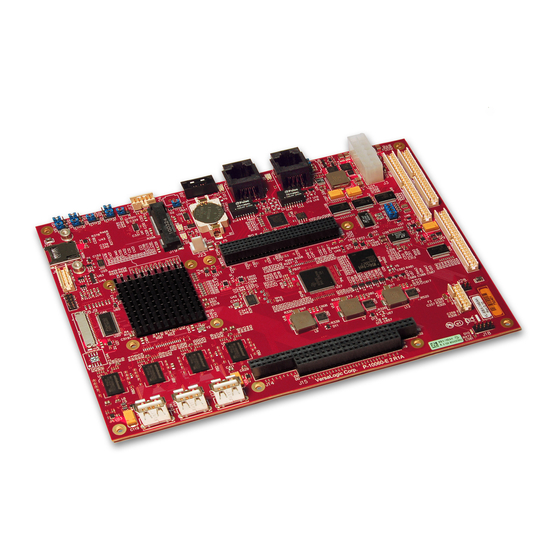
Introduction Description The EBX-11 is a feature-packed single board computer designed for OEM control projects requiring fast processing, industrial I/O, flexible memory options and designed-in reliability and longevity (product lifespan). Its features include: AMD LX 800 microcontroller PCI-based audio with CS5536 companion chip ... -
Page 8: Technical Specifications
Introduction Technical Specifications Specifications are typical at 25°C with 5.0V supply unless otherwise noted. Board Size: COM1–2 Interface: 5.75" x 8.00" x 1.75"; EBX compliant RS-232, 16C550 compatible, 115k baud Storage Temperature: -40° C to 85° C max. Free Air Operating Temperature: COM3–4 Interface: 0°... -
Page 9: Ebx-11 Block Diagram
Introduction EBX-11 Block Diagram RS-232/422 (2 Ports) to J5 EBX-11 Reference Manual... -
Page 10: Rohs-Compliance
(PBDE) flame retardants, in certain electrical and electronic products sold in the European Union (EU) beginning July 1, 2006. VersaLogic Corporation is committed to supporting customers with high-quality products and services meeting the European Union’s RoHS directive. -
Page 11: Transient Voltage Suppression (Tvs) Devices
Introduction (TVS) D RANSIENT OLTAGE UPPRESSION EVICES The EBX-11 circuitry is protected from spike and surge damage by on-board transient voltage suppression (TVS) devices on the user I/O signals. Figure 1 shows a typical example of TVS circuitry. In order for the TVS devices to function properly, they must be connected to earth ground. -
Page 12: Technical Support
Click the link below to see all KnowledgeBase articles related to the EBX-11. VersaTech KnowledgeBase If you have further questions, contact VersaLogic Technical Support at (503) 747-2261. VersaLogic support engineers are also available via e-mail at Support@VersaLogic.com. EPAIR... -
Page 13: Configuration And Setup
Inspect the system visually for any damage that may have occurred in shipping. Contact Support@VersaLogic.com immediately if any items are damaged or missing. Gather all the peripheral devices you plan to attach to the EBX-11 and their interface and power cables. - Page 14 Configuration and Setup CD- ROM OS Installation Power Supply Drive CD-ROM Power to Drives Hard Drive CBR–4406 CBR–5009B PS/2 Keyboard CBR–5009A EBX-11 “Python” Mouse CBR–1201 Analog SVGA Figure 3. Typical Start-up Configuration 1. Install Memory Insert the DRAM module into the SODIMM socket and latch it into place. 2.
- Page 15 Configuration and Setup If you are using a PS/2 keyboard or mouse, plug the breakout cable CBR-5009A into socket J4. If necessary, attach the breakout board CBR-5009B to the cable. (The cable and board are shipped attached.) Plug the keyboard and/or mouse into connector J4 of breakout board.
-
Page 16: Cmos Setup
Configuration and Setup CMOS Setup The default CMOS Setup parameters for the EBX-11 are shown below. See VersaLogic VT1528 – EBX-11 CMOS Setup Reference Knowledgebase article for more information about these parameters. Due to system configuration and changes between BIOS revisions, the information on your monitor may differ from that shown above. -
Page 17: Operating System Installation
The standard PC architecture used on the EBX-11 makes the installation and use of most of the standard x86 processor-based operating systems very simple. The operating systems listed on the VersaLogic OS Compatibility Chart use the standard installation procedures provided by the maker of the OS. -
Page 18: Physical Details
Physical Details Dimensions and Mounting The EBX-11 complies with all EBX standards which provide for specific mounting hole and PC/104-Plus stack locations as shown in the diagram below. 7.80 7.60 0.125 DIA x8 Use 3mm or #4 standoffs 5.80 5.70 2.80 2.65 0.00... - Page 19 Physical Details (Not to scale. All dimensions in inches.) Caution The single board computer must be supported at all eight mounting points to prevent excessive flexing when expansion modules are mated and demated. Flex damage caused by excessive force on an improperly mounted circuit board is not covered under the product warranty.
- Page 20 Physical Details 2.87 0.25 0.25 2.37 0.70 1.95 0.63 0.62 0.06 0.40 Figure 7. CBR-4004 Dimensions and Mounting Holes EBX-11 Reference Manual...
-
Page 21: Hardware Assembly
Physical Details ARDWARE SSEMBLY The EBX-11 mounts on four hardware standoffs using the corner mounting holes (A). These standoffs are secured to the underside of the circuit board using pan head screws. Four additional standoffs (B) must be used under the circuit board to prevent excessive flexing when expansion modules are mated and separated. -
Page 22: External Connectors
Physical Details External Connectors EBX-11 C ONNECTORS Analog, PWM, Digital COM 1-4, Audio, Digital PLED, PS/2 Power I/O, USB 0-1 Keyboard and Mouse, Reset Button, Factory Use Only Speaker Ethernet = Pin 1 J14-J15 PC/104 CompactFlash Ethernet PC/104-Plus SODIMM1 Memory The lower right USB 3 mounting hole... -
Page 23: Ebx-11 Connector Functions And Interface Cables
Physical Details EBX-11 C ONNECTOR UNCTIONS AND NTERFACE ABLES The following table notes the function of each connector, as well as mating connectors and cables, and the page where a detailed pinout or further information is available. Table 1: Connector Functions and Interface Cables Transition Cable Description Pin 1 Location... -
Page 24: Cbr-5009 Connectors
Physical Details CBR-5009 C ONNECTORS (Reserved) Breakout Board Adapter PS/2 Mouse (Top) Keyboard (Bottom) Speaker COM4 COM3 COM1 (Top) COM2 (Bottom) Power (Top) PLED (Bottom) Reset = Pin 1 Figure 10. CBR-5009 Connectors CBR-5009 C ONNECTOR UNCTIONS Connector / Function Part Number Description Component... -
Page 25: Cbr- 4 004 Connectors
Physical Details CBR- 4 004 C ONNECTORS = Pin 1 Figure 11. CBR-4004 Connectors CBR-4004 connector functions depend on the I/O connector to which it is attached, J5 or J10. See Table 5 (J5) or Table 7 (J10) for details. EBX-11 Reference Manual... -
Page 26: Jumper Blocks
Physical Details Jumper Blocks UMPERS HIPPED ONFIGURATION Battery Figure 12. Jumper Block Locations EBX-11 Reference Manual... -
Page 27: Jumper Summary
V2[5-6] Video BIOS Selector In – Primary Video BIOS selected Out – Secondary Video BIOS selected The secondary video BIOS is field-upgradeable using the BIOS upgrade utility. See www.VersaLogic.com/private/pythonsupport.asp for more information. – V2[7-8] System BIOS Selector In – Normal Operation Out –... -
Page 28: System Features
System Features Power Supply OWER ONNECTORS Main power is applied to the EBX-11 through an EPIC-style 10-pin polarized connector at location J3. Warning! To prevent severe and possibly irreparable damage to the system, it is critical that the power connectors are wired correctly. Make sure to use both +5VDC pins and all ground pins to prevent excess voltage drop. -
Page 29: Lithium Battery
Type PC2700 compatible (DDR 333 MHz) Note CMOS settings default to DDR 333 MHz. Settings to DDR 400 MHz are available, but VersaLogic only guarantees operation at the default settings. CMOS RAM CMOS RAM LEARING A jumper may be installed into V3[2-3] to erase the contents of the CMOS RAM and the Real- Time Clock. -
Page 30: Cmos Setup Defaults
System Features CMOS Setup Defaults The EBX-11 permits users to modify the CMOS Setup defaults. This allows the system to boot up with user-defined settings if CMOS RAM is cleared or corrupted. All CMOS setup defaults can be changed, except the time and date. The CMOS Setup defaults can be updated with the Flash BIOS Update (FBU) Utility, available from the General BIOS Information page. -
Page 31: Real Time Clock
System Features Real Time Clock The EBX-11 features a battery-backed 146818-compatible real-time clock/calendar chip. Under normal battery conditions, the clock maintains accurate timekeeping functions when the board is powered off. ETTING THE LOCK The CMOS Setup utility (accessed by pressing the Delete key during a system boot) can be used to set the time/date of the real-time clock. -
Page 32: Interfaces And Connectors
A number of interfaces on the EBX-11 are grouped together and made accessible through utility I/O connectors J4, J5, and J10. A number of cables and boards are available from VersaLogic that provide discrete connectors for each of the interfaces; however, you may wish to create custom cables that surface only the interfaces required by your application. -
Page 33: J5 I/O Connector
Interfaces and Connectors J5 I/O C ONNECTOR The 40-pin I/O connector (J5) incorporates the PWM interfaces, 16 digital I/O channels, and eight analog channels. Table 5 shows the function of each pin. Note On Rev. 4 boards, the TACH input, PWM output, and Digital I/O 0-10 signals were nonstandard. - Page 34 Interfaces and Connectors Table 6: J5 I/O Connector Pinout – Rev. 4.xx and Earlier Boards CBR-4004 CBR-4004 CBR-4004 Signal J5 Pin Connector Pin (Label)* TACH_IN 3 5 (IO1) 4 (IO2) PWM_OUT1 3 (IO3) TACH_IN 2 2 (IO4) 1 (GND1) PWM_OUT2 5 (IO5) TACH_IN 1 4 (IO6)
-
Page 35: J10 I/O Connector
Interfaces and Connectors J10 I/O C ONNECTOR The 40-pin I/O connector (J10) incorporates the USB0 and USB1 interfaces, 16 digital I/O channels, and the audio interface. Table 7 illustrates the function of each pin. Table 7: J10 I/O Connector Pinout CB-4004 CBR-4004 Signal... -
Page 36: Ide
Interfaces and Connectors One IDE interface is available to connect up to two IDE devices, such as hard disks and CD- ROM drives. If the on-board CompactFlash is configured for use, only one other IDE device can be attached to the IDE controller. Connector J12 provides the interface to the IDE controller. Jumper V2[1-2] determines if the CompactFlash plugged into J11 is the master device or slave. -
Page 37: Serial Ports
Interfaces and Connectors Serial Ports The EBX-11 features four on-board 16550-based serial channels located at standard PC I/O addresses. COM1 and COM2 are RS-232 (115.2K baud) serial ports. IRQ lines are chosen in CMOS Setup. COM3 and COM4 can be operated in RS-232 or RS-422 mode. Additional non-standard baud rates are also available (programmable in the normal baud registers) of up to 460k baud. -
Page 38: Serial Port Connectors
ONNECTORS See the Connector Location Diagrams on pages 16 for connector and cable information. The pinouts of the DB9M connectors apply to the serial connectors on the VersaLogic breakout board CBR-5009. These connectors use IEC 61000-4-2-rated TVS components to help protect against ESD damage. -
Page 39: Parallel Port
Interfaces and Connectors Parallel Port The EBX-11 includes a standard bi-directional/EPP/ECP compatible LPT port (connector J18) which resides at the PC standard address of 378h. The port can be enabled or disabled and interrupt assignments can be made via the CMOS setup screen. The LPT mode is also set via the CMOS setup screen. -
Page 40: Ps/2 Keyboard And Mouse
A standard PS/2 keyboard and mouse interface is accessible through connector J4 of the VersaLogic breakout board, CBR-5009. The breakout board is connected to connector J4 of the EBX-11. The 5V power provided to the keyboard and mouse is protected by a 1 Amp fuse. -
Page 41: Usb
Interfaces and Connectors The USB interface on the EBX-11 is OHCI (Open Host Controller Interface) and EHCI (Enhance Host Controller Interface) compatible, which provides a common industry software/hardware interface. There are four USB ports, one at connector J20, one at J21, and two at J10. The J20 and J21 connectors are standard USB Series A sockets. - Page 42 Interfaces and Connectors Table 15 USB2-3 Interface Connector J13 – Rev. 4.01 and Earlier Signal J13 Pin Name Function USBP2PWR +5V (Protected) Channel 2 Data – USBP2– USBP2+ Channel 2 Data + Ground Ground USBP3PWR +5V (Protected) Channel 3 Data – USBP3–...
-
Page 43: Compactflash
IDE interface at connector J12. The CF interface supports operation in DMA mode. The following CF modules have been tested and qualified as bootable devices by VersaLogic. Part numbers with a suffix of -3500 are RoHS-compliant. -
Page 44: Programmable Led
Interfaces and Connectors After installing the OS, you may configure the CF to be the first boot device, which will reduce boot time. This slave-only restriction does not apply to EBX-11 Rev. 5.03 or later boards. Programmable LED Connector J4 includes an output signal for attaching a software controlled LED. Connect the cathode of the LED to J4, pin 48;... -
Page 45: Video Interface
Interfaces and Connectors Video Interface An on-board video controller integrated into the chipset provides high performance video output for the EBX-11. ONFIGURATION The video interface uses PCI interrupt INTA*. CMOS Setup is used to select the IRQ line routed to INTA*. The EBX-11 uses shared memory architecture. -
Page 46: Lvds Flat Panel Display Connector
CMOS Setup provides several options for standard LVDS Flat Panel types. If these options do not match the requirements of the panel you are attempting to use, contact Support@VersaLogic.com for a custom video BIOS. The 3.3V power provided to pins 19 and 20 of J9 is protected by a 1 Amp fuse. -
Page 47: Compatible Lvds Panel Displays
Interfaces and Connectors LVDS P OMPATIBLE ANEL ISPLAYS The following flat panel displays are reported to work properly with the integrated graphics video controller chip used on the EBX-11. Table 19: Compatible Flat Panel Displays Panel Panel Manufacturer Model Number Size Resolution Interface... -
Page 48: Ethernet Interface
The EBX-11 features two Intel 82551ER Fast Ethernet controllers on-board. While these controllers are not NE2000-compatible, they are widely supported. Drivers are readily available to support a variety of operating systems. See VersaLogic website for latest OS support. BIOS C ONFIGURATION Each Ethernet controller can be enabled or disabled in CMOS Setup. -
Page 49: Audio
Codec. This interface is AC’97 2.3 compatible. Drivers are available for most Windows-based operating systems. To obtain the most current versions, consult the EBX-11 product support page at http://www.versalogic.com/private/pythonsupport.asp. J10 provides the line-level stereo input and line-level stereo output connection points. The outputs will drive any standard-powered PC speaker set. -
Page 50: Industrial I/O Functions And Spi Interface
Interfaces and Connectors Industrial I/O Functions and SPI Interface The EBX-11 employs a set of I/O registers for controlling on-board analog input, digital I/O, and external serial peripheral interface (SPI) devices. These functions share control and data registers located at I/O addresses 1D8h through 1DDh. The SPI bus specifies four logic signals: ... -
Page 51: Spi Control Registers
Interfaces and Connectors SPI C ONTROL EGISTERS This section describes the SPI registers for the EBX-11 Rev. 6.00 and later. Appendix B – Legacy SPI Interface describes the SPI registers for Rev. 5.xx and earlier. SPICONTROL (READ/WRITE) 1D8h CPOL CPHA SPILEN1 SPILEN0 MAN_SS... - Page 52 Interfaces and Connectors SPISTATUS (READ/WRITE) 1D9h IRQSEL1 IRQSEL0 SPICLK1 SPICLK0 HW_IRQ_EN LSBIT_1ST HW_INT BUSY Table 24: SPI Control and Status Register Bit assignments Mnemonic Description IRQ Select – These bits select which IRQ will be asserted when a hardware D7-D6 IRQSEL interrupt from a connected SPI device occurs.
-
Page 53: Spi Data Registers
Interfaces and Connectors SPI D EGISTERS SPIDATA0 (READ/WRITE) 1DAh MSbit LSbit SPIDATA1 (READ/WRITE) 1DBh MSbit LSbit SPIDATA2 (READ/WRITE) 1DCh MSbit LSbit SPIDATA3 (READ/WRITE) 1DDh MSbit LSbit SPIDATA3 contains the most significant byte (MSB) of the SPI data word. A write to this register will initiate the SPI clock and, if the MAN_SS bit = 0, will also assert a slave select to begin an SPI bus transaction. -
Page 54: Analog Input
Interfaces and Connectors Analog Input The EBX-11 employs a multi-range, 12-bit A/D converter that accepts up to eight single-ended input signals. The converter features 500k samples per second, with input range of 0 to +4.095V. The A/D converter is accessed through the SPI interface. OFTWARE ONFIGURATION Configure the SPX registers for Analog Input as shown in Table 22. -
Page 55: Initiating An Analog Conversion
Interfaces and Connectors NITIATING AN NALOG ONVERSION The following procedure can be used to initiate an analog conversion. 1. Write 15h to the SPICONTROL register (I/O address 1D8h) – This value configures the SPI port to select the on-board A/D converter, 16-bit frame length, low SCLK idle state, rising edge SCLK edge, and automatic slave select. -
Page 56: Analog Input Code Example
Interfaces and Connectors NALOG NPUT XAMPLE The following code example illustrates the procedure for reading an analog voltage from the onboard ADC channel 3. A 32bit SPI frame is used to provide a valid single sample. DX, 1D8h AL, 35h ;SPICONTROL: SPI Mode 00, 32bit, auto ADC_SS# DX, AL DX, 1D9h... -
Page 57: Digital I/O Interface
Interfaces and Connectors Digital I/O Interface The EBX-11 includes a 32-channel digital I/O interface. The digital lines are grouped as four 8- bit bi-directional ports. Data direction and output driver type are configurable by software. Input data can be inverted through register settings. Any I/O pin(s) can generate an interrupt on change of state. -
Page 58: Digital I/O Port Configuration
Interfaces and Connectors Table 28: Digital I/O Connections – Channels 16-31 CB-4004 CBR-4004 Signal Connector Pin (Label)* Digital I/O 16 5 (IO9) Digital I/O 17 Digital IO 4 (IO10) Digital I/O 18 3 (IO11) Digital I/O 19 2 (IO12) 1 (GND2) Digital I/O 20 5 (IO13) Digital I/O 21... -
Page 59: Writing To A Digital I/O Port
Interfaces and Connectors AL, 44h ;SPIDATA1: Mirror & Open-Drain interrupts DX, AL DX, 1DCh AL, 0Ah ;SPIDATA2: MCP23S17 address 0x0A DX, AL DX, 1DDh AL, 40h ;SPIDATA3: MCP23S17 write command DX, AL BUSY: MOV DX, 1D9h AL, DX ;Get SPI status AL, 01h ;Isolate the BUSY bit BUSY... - Page 60 Interfaces and Connectors DX, 1DDh AL, 40h ;SPIDATA3: MCP23S17 write command DX, AL CALL BUSY ;Poll busy flag to wait for SPI transaction ;Write 55h to MCP23S17 register GPIOA DX, 1DBh AL, 55h ;SPIDATA1: data to write DX, AL DX, 1DCh AL, 14h ;SPIDATA2: MCP23S17 register address 00h DX, AL...
-
Page 61: Spx™ Expansion Bus
XPANSION ODULES VersaLogic offers a number of SPX modules that provide a variety of standard functions, such as analog input, digital I/O, CANbus controller, and others. These are small boards (1.2” x 3.775”) that can mount on the PC/104 and PC/104-Plus stack, using standard PC/104 stand-offs, or up to two feet away from the base board. -
Page 62: Pulse Width Modulation Outputs And Tachometer Inputs
Interfaces and Connectors Pulse Width Modulation Outputs and Tachometer Inputs The EBX-11 incorporates three pulse width modulation (PWM) outputs and three tachometer (TACH) inputs which can be used, in a limited fashion, as general purpose frequency generators and counter/timers. The PWM output frequency options are: 11.0 Hz, 14.6 Hz, 21.9 Hz, 29.3 Hz, 35.2 Hz, 44.0 Hz, 58.6 Hz, 87.7 Hz, 15 kHz, 20 kHz, 25 kHz, and 30 kHz. - Page 63 Interfaces and Connectors ;Set PWMs to manual mode (required) PWM 1 Configuration Register = 5Ch PWM 2 Configuration Register = 5Dh PWM 3 Configuration Register = 5Eh DX, C70h AL, 5Ch ;PWM 1 Configuration Register DX, AL DX, C71h AL, DX ;Read Current Value AL, E0h ;Set Manual Mode...
- Page 64 Interfaces and Connectors X4 = 35.2Hz XA = 30 KHz X5 = 44.0Hz XB = 25 KHz (default) DX, C70h AL, 5Fh ;Zone 1 Range/PWM 1 Frequency DX, AL DX, C71h AL, DX ;Read Current Value AL, F1h ;Set to 14.6 Hz DX, AL ;Re-start the SCH3114 Hardware Monitor (required) DX, C70h...
-
Page 65: Pc/104 Expansion Bus
Interfaces and Connectors PC/104 Expansion Bus EBX-11 has limited support of the PC/104 bus. Most PC/104 cards will work, but be sure to check the requirements of your PC/104 card against the list below. PC/104 I/O S UPPORT The ISA I/O ranges listed below are supported. The I/O ranges allocated to COM ports 1-4 are available to ISA when the on-board COM port function is disabled in CMOS Setup. -
Page 66: System Resources And Maps
System Resources and Maps Memory Map The lower 1 MB memory map of the EBX-11 is arranged as shown in the following table. Various blocks of memory space between C0000h and FFFFFh can be shadowed. CMOS Setup is used to enable or disable this feature. Table 31: Memory Map Start Address End Address... -
Page 67: Interrupt Configuration
System Resources and Maps Interrupt Configuration The EBX-11 has the standard complement of PC type interrupts. Four non-shared interrupts are routed to the PC/104 bus, and up to four IRQ lines can be allocated as needed to PCI devices. There are no interrupt configuration jumpers. All configuration is handled through CMOS Setup. The switches in Figure 11 indicate the various CMOS Setup options. -
Page 68: Special Registers
Special Registers Special Control Register SCR (READ/WRITE) 1D0h PLED Reserved Reserved Reserved Reserved Reserved Reserved Reserved Table 33: Special Control Register Bit Assignments Mnemonic Description Light Emitting Diode — Controls the programmable LED on connector J4. PLED Turns LED off Turns LED on –... -
Page 69: Jumper And Status Register
Special Registers Jumper and Status Register JSR (READ/WRITE) 1D2h (or 1E2h via the CMOS setup) Reserved VB_SEL BRM_SEL Reserved Reserved Reserved Reserved Table 35: Jumper and Status Register Bit Assignments Mnemonic Description – Reserved — This bit has no function. General Purpose Input —... -
Page 70: Appendix A - References
LX 800 Chipset Ethernet Controller Intel Corporation (http://developer.intel.com/sites/developer) Intel 82551ER PC/104 Specification PC/104 Consortium (www.controlled.com/pc104) PC/104 Resource Guide PC/104-Plus Specification VersaLogic Corporation (www.versalogic.com) PC/104 Resource Guide General PC Documentation Microsoft Press (www.microsoft.com/learning/books) The Programmer’s PC Sourcebook Powell’s Books General PC Documentation (www.powells.com) -
Page 71: Appendix B - Legacy Spi Interface
Appendix B – Legacy SPI Interface Improvements to the SPI interface were incorporated into the EBX-11 Revision 6.00 and later boards. The SPI registers and functions of the SPI controller were redesigned for better performance and ease of use. This appendix contains the SPI registers for the EBX-11 Revision 5.xx and earlier boards. - Page 72 Legacy SPI Interface SPICON1 (READ/WRITE) 1D8h INT0 BUSY CLK1 CLK0 Table 36: SPI Control Register 1 Bit Assignments Mnemonic Description SPI Interrupt on Completion Enable – Setting this bit enables the SPI INT0 controller to generate an interrupt on completion of every SPI transaction. SPI interrupts disabled SPI interrupts enabled This IRQ is shared among all SPI devices on-board and connected to the...
- Page 73 Legacy SPI Interface SPICON2 (READ/WRITE) 1D9h INT1 Reserved SPISET1 SPISET0 Reserved DONE Reserved Table 37: SPI Control Register 2 Bit assignments Mnemonic Description SPI Hardware Interrupt Enable – Setting this bit enables SPI devices with a INT1 hardware interrupt feature to generate an interrupt request. SPI device interrupts disabled SPI device interrupts enabled This IRQ is shared among all SPI devices on-board and connected to the...
- Page 74 Legacy SPI Interface SPIDATA1 (READ/WRITE) 1DAh SPIDATA2 (READ/WRITE) 1DBh SPIDATA3 (READ/WRITE) 1DCh Note Writing any value to SPIDATA3 will initiate an SPI transaction based on current SPICON1 and SPICON2 settings. SPICON3 (WRITE ONLY) 1DDh Reserved Reserved Reserved Reserved SPIINT3 SPIINT2 SPIINT1 SPIINT0 Table 38: SPI Control Register 3 Bit Assignments...
Need help?
Do you have a question about the Python EBX-11 and is the answer not in the manual?
Questions and answers