
Related Manuals for VersaLogic VL-EPU-4011


Summary of Contents for VersaLogic VL-EPU-4011
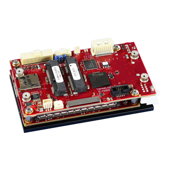
- Page 1 BIOS Reference Manual REV. May 2020 Harrier (VL-EPU-4011) A credit-card sized system featuring error correcting memory (ECC), TPM security, dual or quad core Apollo Lake processor, and plenty of on-board I/O.
- Page 2 Copyright © 2020 VersaLogic Corp. All rights reserved. Notice: Although every effort has been made to ensure this document is error-free, VersaLogic makes no representations or warranties with respect to this product and specifically disclaims any implied warranties of merchantability or fitness for any particular purpose.
- Page 3 Specify the shipping method you prefer and provide a purchase order number for invoicing the repair. Note: Mark the RMA number provided by VersaLogic clearly on the outside of the box before returning. VL-EPU-4011 BIOS Reference Manual...
-
Page 4: Handling Care
CMOS RAM to become corrupted through careless handling, resulting in CMOS resetting to factory defaults. Earth Ground Requirement CAUTION: All mounting standoffs should be connected to earth ground (chassis ground). This provides proper grounding for EMI purposes. VL-EPU-4011 BIOS Reference Manual... -
Page 5: Table Of Contents
System Setup→Intel(R) UltraBook Event Support ............68 System Setup→PEP Constraints Configuration ............... 69 System Setup→RTD3 settings ..................73 System Setup→Memory ECC Error Logging ..............77 Security ........................77 Security→TPM Configuration ..................78 Security→Secure Boot Configuration ................81 VL-EPU-4011 BIOS Reference Manual... - Page 6 IPv4 Network Configuration ..................89 IPv6 Network Configuration ..................89 IPv6 Network Configuration→IPv6 Current Setting ............89 Figures Figure 1. The Harrier (VL-EPU-4011) ......................7 Tables Table 1. Top-level Menu Bar Features ......................10 Table 2. BIOS Setup Program Function Keys ....................10...
-
Page 7: Introduction
Slightly larger in size than a credit card and one inch thick, the Harrier is a member of VersaLogic’s family of small, ultra-rugged embedded x86 computers. Equipped with a powerful dual- or quad-core Intel “Apollo Lake”... - Page 8 The Harrier is designed and tested for full industrial temperature (-40º to +85ºC) operation and meets MIL-STD-202H specifications for shock and vibration. It also features an on-board voltage regulation for dependable operation from nominal 12V sources. VL-EPU-4011 BIOS Reference Manual...
-
Page 9: Technical Specifications
Introduction VersaLogic’s 10+ year product life support programs ensure long-term availability. This avoids expensive upgrades and migrations that come from short, disposable lifecycle products. Its features include: Intel Atom* Apollo Lake SATA port supports bootable SATA processor with up to 2 GHz burst hard drive clock rate. -
Page 10: Epu-4011 Bios Overview
Loads failsafe default values Exit Save and exit BIOS Help Press the “F1” key anywhere in the Setup Utility to get the General Help page. BIOS menu options are listed which includes a brief description of those options. VL-EPU-4011 BIOS Reference Manual... -
Page 11: Main Menu
Option: Diagnostic Splash Screen Disabled (default) Enabled Details: If you select 'Enabled' the diagnostic splash screen always displays during boot. If you select 'Disabled' the diagnostic splash screen does not display unless you press HOTKEY during boot. VL-EPU-4011 BIOS Reference Manual... - Page 12 Details: Enable/Disable USB BIOS SMM support for mouse, keyboard, mass storage, etc, in legacy operating systems such as DOS. Option: Console Redirection Disabled (default) Enabled Details: Enable/Disable Universal Console Redirection. Option:Terminal Type ANSI (default) VT100 VT100+ UTF8 Details: Set terminal type of UCR. VL-EPU-4011 BIOS Reference Manual...
- Page 13 Details: Enables Console Redirection after OS has loaded. Option: Allow Hotkey in S4 resume Disabled Enabled (default) Details: Enable hotkey detection when system resuming from Hibernate state Option: UEFI Boot Disabled Enabled (default) Details: Enable the UEFI boot. VL-EPU-4011 BIOS Reference Manual...
-
Page 14: Main Menu→ Network Stack
Details: Load all OPROMs or on demand according to the boot device. Main Menu→ Network Stack Option: Network Stack Disabled (default) Enabled Details: Enable/Disable UEFI Network Stack Option: IPv4 Disabled Enabled (default) Details: Enable/Disable IPv4 Option: IPv6 Disabled Enabled (default) Details: Enable/Disable IPv6 VL-EPU-4011 BIOS Reference Manual... -
Page 15: Main Menu→ Smbios Event Log
If bi-direction is enabled, external agents can drive PROCHOT# to throttle the processor. Option: VTX-2 Disable Enable (default) Details: To enable or disable the VTX-2 Mode support Option: VT-d Disable (default) Enable Details: Enable/Disable VT-d, Please disable IPU when you want to enable VT-D feature VL-EPU-4011 BIOS Reference Manual... - Page 16 Enable (default) Details: Core 0 Enable Option: Core 1 Disable Enable (default) Details: Core 1 Enable/Disable Option: Core 2 Disable Enable (default) Details: Core 2 Enable/Disable Option: Core 3 Disable Enable (default) Details: Core 3 Enable/Disable VL-EPU-4011 BIOS Reference Manual...
-
Page 17: System Setup→ Cpu Configuration→Cpu Power Management
Enable (default) Details: Enable to automatically allow processor cores to run faster than the base operating frequency if it's operating below power, current, and temperature specification limits. Option: C-States Disable Enable (default) Details: Enable/Disable C States VL-EPU-4011 BIOS Reference Manual... - Page 18 Unlimited Details: This option controls the Max Core C State that cores will support. Option: C-State Auto Demotion Disabled C1 (default) Details: Configure C-State Auto Demotion Option: C-State Un-demotion Disabled C1 (default) Details: Configure C-State Un-demotion VL-EPU-4011 BIOS Reference Manual...
- Page 19 Option: Power Limit 1 Clamp Mode Disabled Enabled (default) Details: Enable/Disable Power Limit 1 Clamp Mode Option: Power Limit 1 Power Auto (default) Details: Power Limit 1 in Watts. Auto will program Power Limit 1 based on silicon default support value VL-EPU-4011 BIOS Reference Manual...
-
Page 20: System Setup→Uncore Configuration
Disable (default) Details: Enable/Disable Pei (Early) Display ---- IGD Configuration ---- Option: Integrated Graphics Device Disable Enable (default) Details: Enable : Enable Integrated Graphics Device (IGD) when selected as the Primary Video Adaptor. Disable: Alwarys disable IGD VL-EPU-4011 BIOS Reference Manual... - Page 21 Details: Check to enable render standby support, RC6 should be enabled if S0ix is enabled. This item will be read only if S0ix is enabled Option: GTT Size 8MB (default) Details: Select the GTT Size Option: Aperture Size 256MB (default) Details: Select the Aperture Size VL-EPU-4011 BIOS Reference Manual...
- Page 22 Details: Select DVMT5.0 Total Graphic Memory size used by the Internal Graphics Device Option: Cd Clock Frequency 144 MHz 288 MHz 384 MHz 576 MHz 624 MHz (default) Details: Select the highest Cd Clock frequency supported by the platform VL-EPU-4011 BIOS Reference Manual...
- Page 23 Option: IGD Flat Panel Disabled Auto 800 x 480 (EDID #0) 800 x 600 (EDID #1) 1024 x 768 (EDID #2) (default) 1280 x 800 (EDID #3) Details: Option: IGD Flat Panel Color Depth 18-bit 24-bit (default) Details: VL-EPU-4011 BIOS Reference Manual...
- Page 24 Disable Details: Enable/Disable Memory Scrambler support. Option: SA IPU ACPI mode Disable (default) IGFX Child ACPI Details: AUTO: IPU will be IGFX Child device when IGFX enabled. IGFX Child: Force IGFX Child device. ACPI:Force ACPI device VL-EPU-4011 BIOS Reference Manual...
-
Page 25: System Setup→South Cluster Configuration→Hd-Audio Configuration
Option: HD-Audio I/O Buffer Ownership Select HD-Audio link owns all the I/O buffers I2S port owns all the I/O buffers (default) Details: Set HD-Audio I/O Buffer Ownership Option: HD-Audio Clock Gating Disable Enable (default) Details: Enable/Disable HD-Audio Clock Gating VL-EPU-4011 BIOS Reference Manual... - Page 26 Applicable only if iDisp codec supports selected frequency. Option: iDisplay Link T-Mode 2T Mode (default) 1T Mode Details: Selects iDisplay Link T-Mode for 48MHz: 2T - SDI data held for 2 BCLKs. 1T - SDI data held for 1 BCLK. VL-EPU-4011 BIOS Reference Manual...
-
Page 27: System Setup→South Cluster Configuration→Gmm Configuration
Option: GMM Clock Gate - Sideband Clock Trunk Disable Enable (default) Details: Enable/Disable GMM Clock Gate - Sideband Clock Trunk Option: GMM Clock Gate - Sideband Clock Partition Disable Enable (default) Details: Enable/Disable GMM Clock Gate - Sideband Clock Partition VL-EPU-4011 BIOS Reference Manual... - Page 28 Details: Enable/Disable GMM Clock Gate - Host Interface Option: GMM Clock Gate - Partition Disable Enable (default) Details: Enable/Disable GMM Clock Gate - Partition Option: GMM Clock Gate - Trunk Disable Enable (default) Details: Enable/Disable GMM Clock Gate - Trunk VL-EPU-4011 BIOS Reference Manual...
-
Page 29: System Setup→South Cluster Configuration→Ish Configuration
Option: GMM Power Gate - PMC Request Disable (default) Enable Details: Enable/Disable GMM Power Gate - PMC Request System Setup→South Cluster Configuration→ISH Configuration Option: ISH Controller Disabled (default) Enabled Details: Enable/Disable Integrated Sensor Hub (ISH) Device VL-EPU-4011 BIOS Reference Manual... -
Page 30: System Setup→South Cluster Configuration→Lpss Configuration
Option: LPSS I2C #2 Support (D22:F1) Disable PCI Mode (default) ACPI Mode Details: Enable/Disable LPSS I2C #2 Support Option: Set LPSS I2C #2 Speed Standard Mode Fast Mode (default) Fast Plus Mode High Speed Mode Details: Select LPSS I2C #2 Speed VL-EPU-4011 BIOS Reference Manual... - Page 31 Option: LPSS I2C #5 Support (D23:F0) Disable (default) PCI Mode ACPI Mode Details: Enable/Disable LPSS I2C #5 Support Option: Set LPSS I2C #5 Speed Standard Mode Fast Mode (default) Fast Plus Mode High Speed Mode Details: Select LPSS I2C #5 Speed VL-EPU-4011 BIOS Reference Manual...
- Page 32 Option: Set LPSS I2C #7 Speed Standard Mode Fast Mode (default) Fast Plus Mode High Speed Mode Details: Select LPSS I2C #7 Speed Option: LPSS I2C #8 Support (D23:F3) Disable (default) PCI Mode ACPI Mode Details: Enable/Disable LPSS I2C #8 Support VL-EPU-4011 BIOS Reference Manual...
- Page 33 Option: LPSS HSUART #3 Support (D24:F2) Disable PCI Mode ACPI Mode (default) Details: Enable/Disable LPSS HSUART #2 Support Option: LPSS HSUART #4 Support (D24:F3) Disable (default) PCI Mode ACPI Mode Details: Enable/Disable LPSS HSUART #2 Support VL-EPU-4011 BIOS Reference Manual...
- Page 34 Details: Enable/Disable LPSS I2C #2 Clock Gating Option: LPSS HSUART #3 Clock Gating Configuration Disable Enable (default) Details: Enable/Disable LPSS HSUART #3 Clock Gating Option: LPSS SPI #1 Clock Gating Configuration Disable Enable (default) Details: Enable/Disable LPSS SPI #1 Clock Gating VL-EPU-4011 BIOS Reference Manual...
-
Page 35: System Setup→South Cluster Configuration→Pci Express Configuration
Details: Select PCI Express Port8xh Decode Root Port. User to ensure port availability Option: Peer Memory Write Enable Disabled (default) Enabled Details: Peer Memory Write Enable/Disable Option: Compliance Mode Disabled (default) Enabled Details: Compliance Mode Enable/Disable VL-EPU-4011 BIOS Reference Manual... -
Page 36: System Setup→Pci Express Root Port [1-6]
Details: PCI Express Active State Power Management settings Option: L1 Substates Disabled L1.1 L1.2 L1.1 & L1.2 (default) Details: PCI Express L1 Substates settings. Option: ACS Disabled Enabled (default) Details: Enable/Disable Access Control Services Extended Capability VL-EPU-4011 BIOS Reference Manual... - Page 37 Enable Details: PCI Express Device Correctable Error Reporting Enable/Disable Option: CTO Disabled (default) Enabled Details: PCI Express Completion Timer TO Enable/Disable. Option: SEFE Disable (default) Enable Details: Root PCI Express System Error on Fatal Error Enable/Disable VL-EPU-4011 BIOS Reference Manual...
- Page 38 Details: PCI Express PME SCI Enable/Disable Option: Hot Plug Disable (default) Enable Details: PCI Express Hot Plug Enable/Disable Option: PCIe Speed Auto (default) Gen1 Gen2 Details: Configure PCIe Speed Option: Transmitter Half Swing Disable (default) Enable Details: Transmitter Half Swing Enable/Disable. VL-EPU-4011 BIOS Reference Manual...
- Page 39 Enabled (default) Details: PCH PCIE Latency Reporting Enable/Disable Option: Snoop Latency Override Disabled Manual Auto (default) Details: Snoop Latency Override for PCH PCIE. Disabled: Disable override. Manual: Manually enter override values. Auto (default): Maintain default BIOS flow. VL-EPU-4011 BIOS Reference Manual...
- Page 40 Auto (default): Maintain default BIOS flow. Option: Non Snoop Latency Value Minimum = 0x0000 Maximum = 0x03FF Default = 0x003C Details: LTR Non Snoop Latency value of PCH PCIE Option: Non Snoop Latency Multiplier 1 ns VL-EPU-4011 BIOS Reference Manual...
- Page 41 Option: PCH PCIE LTR Disabled Enabled (default) Details: PCH PCIE Latency Reporting Enable/Disable Option: Snoop Latency Override Disabled Manual Auto (default) Details: Snoop Latency Override for PCH PCIE. Disabled: Disable override. Manual: Manually enter override values. VL-EPU-4011 BIOS Reference Manual...
- Page 42 Disabled: Disable override. Manual: Manually enter override values. Auto (default): Maintain default BIOS flow. Option: Non Snoop Latency Value Minimum = 0x0000 Maximum = 0x03FF Default = 0x003C Details: LTR Non Snoop Latency value of PCH PCIE VL-EPU-4011 BIOS Reference Manual...
-
Page 43: System Setup→South Cluster Configuration→Sata Drives
---- Chipset-SATA Controller Configuration ---- Option: Chipset SATA Enable (default) Disable Details: Enables or Disables the Chipset SATA Controller. The Chipset SATA controller supports the 2 black internal SATA ports (up to 3Gb/s supported per port). VL-EPU-4011 BIOS Reference Manual... - Page 44 Disabled (default) Enabled Details: If enabled, SATA port will be reported as Hot Plug capable. Option: Mechanical Presence Switch Disabled Enabled (default) Details: Controls reporting if this port has an Mechanical Presence Switch. Note: Requires hardware support. VL-EPU-4011 BIOS Reference Manual...
- Page 45 Disabled (default) Enabled Details: Enable/Disable DITO Configuration Option: DITO Value Minimum = 0x0000 Maximum = 0x03FF Default = 0x0271 Details: DITO Value Option: DM Value Minimum = 0x00 Maximum = 0x0F Default = 0x0F Details: DM Value VL-EPU-4011 BIOS Reference Manual...
- Page 46 Details: Identify the SATA port is connected to Solid State Drive or Hard Disk Drive Option: SATA Port 1 DevSlp Disabled (default) Enabled Details: Enable/Disable SATA Port 1 DevSlp. Board rework for LP needed before enable. VL-EPU-4011 BIOS Reference Manual...
-
Page 47: System Setup→South Cluster Configuration→Scc Configuration
Details: DM Value System Setup→South Cluster Configuration→SCC Configuration Option: SCC SD Card Support (D27:F0) Disable Enable (default) Details: Enable/Disable SCC SD Card Support Option: SCC eMMC Support (D28:F0) Disable Enable (default) Details: Enable/Disable SCC eMMC Support VL-EPU-4011 BIOS Reference Manual... -
Page 48: System Setup→South Cluster Configuration→Usb Configuration
OS. Do not disable it unless for debug purpose. Option: USB VBUS ON (default) Details: VBUS should be ON in HOST mode. It should be OFF in OTG device mode. VL-EPU-4011 BIOS Reference Manual... - Page 49 Connection to the controller. Option: USB Port #[0-7] Disable Enable (default) Details: Enable/Disable USB port. Once disabled, any USB devices plug into the connector will not be detected by BIOS or OS. Option: USB 3 Port #[0-1] VL-EPU-4011 BIOS Reference Manual...
-
Page 50: System Setup→South Cluster Configuration→Miscellaneous Configuration
Details: Enable/Disable USB HW MODE AFE Comparators System Setup→South Cluster Configuration→Miscellaneous Configuration Option: High Precision Timer Disable Enable (default) Details: Enable or Disable the High Precision Event Timer Option: 8254 Clock Gating Disable (default) Enable Details: Enable or Disable 8254 Clock Gating VL-EPU-4011 BIOS Reference Manual... - Page 51 Details: Enable/Disable the SC BIOS Lock Enable feature. Required to be enabled to ensure SMM protection of flash. Option: RTC Lock Disabled Enabled (default) Details: Enable will lock bytes 38h-3Fh in the lower/upper 128-byte bank of RTC RAM VL-EPU-4011 BIOS Reference Manual...
-
Page 52: System Setup→Boot
Details: Select the target OS. Option: Silent Boot Disable (default) Enable Details: Disable console output and show logo if it is enabled. Option: EFI Network Disabled (default) Enabled Details: Enable/Disable EFI Network support for onboard LAN. VL-EPU-4011 BIOS Reference Manual... -
Page 53: System Setup→Security Configuration
--- TXE Configuration ---- Option: SEC Disabled Enabled (default) Details: Option: SeC HMRFPO Disabled (default) Enabled Details: Option: SeC Firmware Update Disabled (default) Enabled Details: Option: SeC EOP Message Disabled Enabled (default) Details: Send EOP Message Before Enter OS VL-EPU-4011 BIOS Reference Manual... -
Page 54: System Setup→Thermal
Option: ACPI Thermal Zone Disabled Enabled (default) Details: Enable ACPI Thermal Zone Trip Points (_AC0, _CRT, _HOT, _PSV) Option: Critical Trip Point 15 C 23 C 31 C 39 C 47 C 55 C 63 C VL-EPU-4011 BIOS Reference Manual... - Page 55 119 C (default) 125 C Details: This value controls the temperature of the ACPI Hot Trip Point - the point in which the OS will enter the S4 sleeping state. Option: Passive Trip Point 95 C VL-EPU-4011 BIOS Reference Manual...
- Page 56 71 C 79 C 87 C 95 C 103 C 110 C Details: This value controls the temperature of the ACPI Active Trip Point - the point in which the OS will turn the fan on. VL-EPU-4011 BIOS Reference Manual...
-
Page 57: System Setup→System Component
Option: OS Reset Select Warm Reset Cold Reset (default) Details: Select the reset type in FACP table Option: Embedded Power Instrumentation Disable (default) Enable Details: Enable/Disable EPI feature Option: USB TypeC Disable Enable Auto (default) VL-EPU-4011 BIOS Reference Manual... - Page 58 Option: DDR Clock Bending Selection Table 1.3% 0.6% 0% (No Clock Bending) (default) -0.9% Details: Choose for clock bending Option: HighSpeed SerialIO SSC Disable Enable (default) Details: Enable High Speed Serial IO Spread Spectrum Clocking configuration VL-EPU-4011 BIOS Reference Manual...
-
Page 59: System Setup→Debug Configuration
---- APEI BERT Configuration ---- Option: APEI BERT Enable (default) Disable Details: Enable or Disable APEI BERT ---- ACPI Memory Debug Switch ---- Option: ACPI Memory Debug Disable (default) Enable Details: Enable or Disable ACPI Memory Debug VL-EPU-4011 BIOS Reference Manual... - Page 60 Option: TDO GPIO Pin Disable Enable (default) Auto Details: If Auto is selected, TDO will be disabled for A0 silicon only. For other steppings, TDO will be enabled. Option: SMRR Disable Enable (default) Details: Disable/Enable SMRR VL-EPU-4011 BIOS Reference Manual...
- Page 61 Disable (default) Details: Enable OS Dnx Option: ISH GPIO(I2C0) Pull Up Enable (default) Disable Details: ISH GPIO I2C0 Enable/Disable Pull Up's Option: ISH GPIO(I2C1) Pull Up Enable (default) Disable Details: ISH GPIO I2C1 Enable/Disable Pull Up's VL-EPU-4011 BIOS Reference Manual...
- Page 62 Details: Enable/Disable processor trace feature from CPU MSR. Enabling this feature will immediately start trace collection. Option: Processor Trace OutPut Scheme Single Range Output (default) ToPA Output Details: Select Single Range Output scheme or ToPA table Output scheme VL-EPU-4011 BIOS Reference Manual...
-
Page 63: System Setup→Npk Debug Configuration
Enable (default) Details: FW Trace Function Enable Option: FW Trace Destination Memory Region 0 PTI (default) USB 3 BSSB Details: Select FW Trace Destination Option: NPK Recovery Dump Disable (default) Enable Details: Enable NPK Recovery dump feature VL-EPU-4011 BIOS Reference Manual... - Page 64 Details: Memory Region 0 Buffer WrapAround Option: Memory Region 1 Buffer Size None (default) 64MB 128MB 256MB 512MB Details: Select Memory Region 1 Buffer Size Option: Memory Region 1 Buffer WrapAround NoWrap Wrap (default) Details: Memory Region 1 Buffer WrapAround VL-EPU-4011 BIOS Reference Manual...
- Page 65 Quarter Speed (default) Details: PTI Speed Option: Punit Message Level LEVEL NONE LEVEL LOW (default) LEVEL MEDIUM LEVEL HIGH LEVEL DEFAULT Details: Punit Message Output Verbosity Level. LEVEL DEFAULT means that IAFW will not change Verbosity level VL-EPU-4011 BIOS Reference Manual...
-
Page 66: System Setup→Acpi Settings
Details: On enable, Vista will control the ASPM support for the device. If disabled, the BIOS will. Option: Intel Ready Mode Technology Disabled (default) Enabled Details: Enable/Disable Ready Mode support based on Windows Away-mode. Only on DT/AIO. VL-EPU-4011 BIOS Reference Manual... - Page 67 Details: When EC enters Low Power S0 Idle State, the CAPS LOCK light will be turned Option: EC Low Power Mode Disabled (default) Enabled Details: This option controls whether EC will go to Low power mode during Low Power S0 Idle State VL-EPU-4011 BIOS Reference Manual...
-
Page 68: System Setup→Intel(R) Ultrabook Event Support
Option: Dock Mode boot value Undock (default) Dock Details: Choose Docked or Undocked as boot mode. Option: Dock Mode upon S3 and S4 resume No change (default) Toggle Details: Keep it the same as Sx entry or toggle it. VL-EPU-4011 BIOS Reference Manual... -
Page 69: System Setup→Pep Constraints Configuration
PCIe SSD Port Details: Add Storage device in PEP mitigation list Option: PEP UART Disabled (default) Enabled Details: Add UART in PEP mitigation list Option: PEP SDIO Disabled (default) Enabled Details: Add SDIO in PEP mitigation list VL-EPU-4011 BIOS Reference Manual... - Page 70 Disabled (default) Enabled Details: Add I2C3 in PEP mitigation list Option: PEP I2C4 Disabled (default) Enabled Details: Add I2C4 in PEP mitigation list Option: PEP I2C5 Disabled (default) Enabled Details: Add I2C5 in PEP mitigation list VL-EPU-4011 BIOS Reference Manual...
- Page 71 Disabled (default) Enabled Details: Add HSUART1 in PEP mitigation list Option: PEP HSUART2 Disabled (default) Enabled Details: Add HSUART2 in PEP mitigation list Option: PEP HSUART3 Disabled (default) Enabled Details: Add HSUART3 in PEP mitigation list VL-EPU-4011 BIOS Reference Manual...
- Page 72 Disabled (default) Enabled Details: Add SPI3 in PEP mitigation list Option: PEP XHCI Disabled Enabled (default) Details: Add XHCI in PEP mitigation list Option: PEP Audio Disabled Enabled (default) Details: Add Audio in PEP mitigation list VL-EPU-4011 BIOS Reference Manual...
-
Page 73: System Setup→Rtd3 Settings
Option: VR Staggering delay Minimum = 0x0000 Maximum = 0x0064 Default = 0x0010 Details: Delay between subsequent VR power on to avoid current spike Option: VR Ramp up delay Minimum = 0x0000 Maximum = 0x0064 Default = 0x0010 VL-EPU-4011 BIOS Reference Manual... - Page 74 Option: I2C0 Controller Minimum = 0x0000 Maximum = 0x03E8 Default = 0x0000 Details: Delay in _PS0 I2C0 Controller. Option: SensorHub Minimum = 0x0000 Maximum = 0x03E8 Default = 0x0044 Details: Delay after applying power to SensorHub device. VL-EPU-4011 BIOS Reference Manual...
- Page 75 High Speed: USB2.0 devices will be exposed as RTD3 capable. Disabled : USB RTD3 support disabled. For SawtoothPeak USB Port1(Below) is Superspeed and Port2(Top) is HighSpeed. Check respective board configuration to know about USB port position. VL-EPU-4011 BIOS Reference Manual...
- Page 76 Option: Sata Port 2 Disabled (default) Enabled Details: Setup option to control the SATA port RTD3 functionality Option: MiniCard SATA Port3 Disabled (default) 1.5DX MiniCard 3.3DX MiniCard Details: Setup option to control the SATA port RTD3 functionality VL-EPU-4011 BIOS Reference Manual...
-
Page 77: System Setup→Memory Ecc Error Logging
Details: Controls whether to halt or not when uncorrectable errors are encountered. Security Option: Min. password length Minimum = 0x01 Maximum = 0x14 Default = 0x01 Details: Set the minimum number of characters for password (1-20). VL-EPU-4011 BIOS Reference Manual... -
Page 78: Security→Tpm Configuration
Option: Current TPM State Unknown (default) Enabled and Activated Enabled and Deactivated Disabled and Activated Disabled and Deactivated TPM 2 Details: Option: TPM Action Disable Activate Deactivate Disable and Deactivate Clear Clear, Enable, and Activate No Change (default) Enable VL-EPU-4011 BIOS Reference Manual... - Page 79 Details: Enact TPM Action. Note: Most TPM actions require TPM to be Enabled to take effect. Option: TPM2 Operation Parameter Minimum = 0x00000000 Default = 0x00000000 Maximum = 0xFFFFFFFF Details: Additional TPM2 Operation Parameter need be sent with Operation Code (required for SetPCRBanks) VL-EPU-4011 BIOS Reference Manual...
- Page 80 Option: PCR Bank: SHA384 Unchecked (default) Checked Details: TCG2 Request PCR Bank: SHA384 Option: PCR Bank: SHA512 Unchecked (default) Checked Details: TCG2 Request PCR Bank: SHA512 Option: PCR Bank: SM3_256 Unchecked (default) Checked Details: TCG2 Request PCR Bank: SM3_256 VL-EPU-4011 BIOS Reference Manual...
-
Page 81: Security→Secure Boot Configuration
(including forcing the slot to always be a PCIe Mini Card or an mSATA module). VersaLogic Features→UART Configuration Option: Console Redirection Port UART1 (default) UART2 UART3 UART4 Details: Configure UART port for Console Redirection VL-EPU-4011 BIOS Reference Manual... - Page 82 Details: Enable or disable UART1. Option: Base Address 3F8 (default) Details: Select the base address for UART1. Option: IRQ Disabled IRQ3 IRQ4 (default) IRQ5 IRQ10 IRQ6 IRQ7 IRQ11 Details: Select the IRQ for UART1, or disable it. VL-EPU-4011 BIOS Reference Manual...
- Page 83 Details: Enable or disable UART2. Option: Base Address 2F8 (default) Details: Select the base address for UART2. Option: IRQ Disabled IRQ3 (default) IRQ4 IRQ5 IRQ10 IRQ6 IRQ7 IRQ11 Details: Select the IRQ for UART2, or disable it. VL-EPU-4011 BIOS Reference Manual...
- Page 84 Details: Enable or disable UART3. Option: Base Address 3E8 (default) Details: Select the base address for UART3. Option: IRQ Disabled IRQ3 IRQ4 IRQ5 IRQ10 IRQ6 IRQ7 (default) IRQ11 Details: Select the IRQ for UART3, or disable it. VL-EPU-4011 BIOS Reference Manual...
- Page 85 Details: Enable or disable UART4. Option: Base Address 2E8 (default) Details: Select the base address for UART4. Option: IRQ Disabled IRQ3 IRQ4 IRQ5 IRQ10 IRQ6 (default) IRQ7 IRQ11 Details: Select the IRQ for UART4, or disable it. VL-EPU-4011 BIOS Reference Manual...
-
Page 86: Versalogic Features→Pci Irq Routing Configuration
VersaLogic Features Option: Mode RS-232 (default) RS-422 RS-485 (Manual Direction Control) RS-485 (Automatic Direction Control) Details: Select the mode for UART4. VersaLogic Features→PCI IRQ Routing Configuration Option: PIRQA Routing IRQ3 IRQ4 IRQ5 IRQ6 IRQ7 IRQ9 IRQ10 IRQ11 (default) Details: Configure PCI IRQ Routing Number... - Page 87 Option: PIRQD Routing IRQ3 IRQ4 IRQ5 IRQ6 IRQ7 IRQ9 IRQ10 IRQ11 (default) Details: Configure PCI IRQ Routing Number Option: PIRQE Routing IRQ3 IRQ4 IRQ5 IRQ6 IRQ7 IRQ9 IRQ10 IRQ11 (default) Details: Configure PCI IRQ Routing Number VL-EPU-4011 BIOS Reference Manual...
- Page 88 Option: PIRQG Routing IRQ3 IRQ4 IRQ5 IRQ6 IRQ7 IRQ9 IRQ10 (default) IRQ11 Details: Configure PCI IRQ Routing Number Option: PIRQH Routing IRQ3 IRQ4 IRQ5 IRQ6 IRQ7 IRQ9 IRQ10 IRQ11 (default) Details: Configure PCI IRQ Routing Number VL-EPU-4011 BIOS Reference Manual...
-
Page 89: Ipv4 Network Configuration
Details: The number of consecutive Neighbor Solicitation messages sent while performing Duplicate Address Detection on a tentative address. A value of zero indicates that Duplicate Address Detection is not performed. Option: Policy automatic (default) manual Details: automatic or manual VL-EPU-4011 BIOS Reference Manual...
Need help?
Do you have a question about the VL-EPU-4011 and is the answer not in the manual?
Questions and answers