
Related Manuals for VersaLogic Hawk


Summary of Contents for VersaLogic Hawk
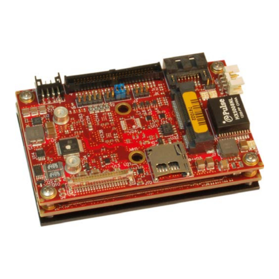
- Page 1 Reference Manual REV. March 2020 Hawk (VL-EPU-3310) Intel Atom™ E38xx-based ® Embedded Processing Unit with SATA, Ethernet, USB, Serial, Video, HD Audio, Mini PCIe Socket, and microSD.
- Page 2 Copyright © 2015-2020 VersaLogic Corp. All rights reserved. Notice: Although every effort has been made to ensure this document is error-free, VersaLogic makes no representations or warranties with respect to this product and specifically disclaims any implied warranties of merchantability or fitness for any particular purpose.
- Page 3 Customer Support If you are unable to solve a problem after reading this manual, visiting the product support page, or searching the KnowledgeBase, contact VersaLogic Technical Support at (503) 747-2261. VersaLogic support engineers are also available via e-mail at Support@VersaLogic.com.
- Page 4 KNOWN ISSUES Hardware † † A microSD card will not function if the Hawk is using Microsoft Windows The eMMC Flash device will not function if the Hawk is using Microsoft Windows 7 VL-EPU-3310 Reference Manual...
-
Page 5: Table Of Contents
VL-HDW-405 Mounting Plate Dimensions ............11 Hardware Assembly ..................... 12 External Connectors ......................14 Baseboard Connector Locations ................14 Hawk Connector Functions and Interface Cables ..........15 Jumper Blocks ........................16 Jumper As-Shipped Configuration ..............16 Jumper Configuration Summary ................17 System Features ...................... - Page 6 Contents Interfaces and Connectors ..................22 I/O Connector ........................22 Ethernet Interface......................24 Ethernet Connector ....................24 Correctly Installing the VL-CBR-0804 Latching Ethernet Cable ....... 25 Ethernet Status LEDs ................... 27 SATA Interface ......................... 28 Mini PCIe / mSATA Socket ..................... 28 W_Disable# Signal ....................
- Page 7 Contents Test Results......................46 Installing VersaLogic Thermal Solutions ................. 50 Installing the VL-HDW-406 Passive Heat Sink ..........50 Installing the VL-HDW-411 Heat Sink Fan ............51 Installing the VL-HDW-408 Heat Pipe Block ............. 52 Appendix A – Mounting Options ................53 Hawk Mounting Configuration ..................
- Page 8 Figure 2. Hawk (VL-EPU-3310) Block Diagram .................... 4 Figure 3. Typical Development Configuration ....................8 Figure 4. Hawk Dimensions and Mounting Holes ..................10 Figure 5. Mounting Plate Dimensions ......................11 Figure 6. Hardware Assembly with Heat Plate Down ................... 12 Figure 7.
-
Page 9: Introduction
Roughly the size of a credit card and less than one inch thick, the Hawk is the embedded industry’s smallest, lightest, ultra-rugged, embedded x86 computer. This embedded computer, †... - Page 10 VersaLogic OS Compatibility Chart). Hawk EPUs are subjected to 100% functional testing and are backed by a limited five-year warranty. Careful parts sourcing and US-based technical support ensure the highest possible quality, reliability, service, and product longevity for this exceptional EPU.
-
Page 11: Technical Specifications
Introduction Technical Specifications Specifications are typical at +25 °C with a +12 V supply unless otherwise noted. Board Size: System Reset: 55 x 84 x 22 mm (2.17 x 3.31 x 0.87 inches) Push-button power reset via paddleboard Watchdog timeout (warm/cold reset) Storage Temperature: Video Interface -40°... -
Page 12: Block Diagram
Introduction Block Diagram Figure 2. Hawk (VL-EPU-3310) Block Diagram VL-EPU-3310 Reference Manual... -
Page 13: Cautions
Note: The exterior coating on some metallic antistatic bags is sufficiently conductive to cause excessive battery drain if the bag comes in contact with the bottom side of the Hawk. Handling Care CAUTION: Avoid touching the exposed circuitry with your fingers when handling the board. Though... -
Page 14: Thermal Considerations
E3800 Series Datasheet for complete information.) Thermal Options The following thermal options are available for the Hawk: VL-HDW-405 – Secondary 75 mm x 84 mm mounting plate. Attaches to heat plate on standard product. Refer to page 11 for more information. -
Page 15: Configuration And Setup
Support@VersaLogic.com immediately if any items are damaged or missing. Gather all the peripheral devices you plan to attach to the Hawk as well as their interface and power cables. It is recommended that you attach standoffs to the board (see Hardware Assembly on page 12) to stabilize the board and make it easier to work with. -
Page 16: Figure 3. Typical Development Configuration
USB Mouse VL-CBR-5016 Paddleboard USB CD- Power Supply ROM Drive VL-CBR- 0807 OS Installation CD-ROM VL-CBR-0401 HAWK SATA Hard Drive VL-CBR- Baseboard 0701/0702 CPU Module LVDS VL-CBR-2015 or VL-CBR-2016 Figure 3. Typical Development Configuration 1. Attach Cables and Peripherals ... -
Page 17: Operating System Installation
Install the operating system according to the instructions provided by the operating system manufacturer. Operating System Installation The standard PC architecture used on the Hawk makes the installation and use of most of the standard x86-based operating systems very simple. The operating systems listed on the VersaLogic Software Support page use the standard installation procedures provided by the maker of the operating system. -
Page 18: Physical Details
Physical Details Dimensions and Mounting Hawk Dimensions The Hawk complies with the COM Express mini form factor standard. Figure 4 provides the board’s dimensions to assist with pre-production planning and layout. Figure 4. Hawk Dimensions and Mounting Holes (Not to scale. All dimensions in millimeters.) -
Page 19: Vl-Hdw-405 Mounting Plate Dimensions
Physical Details VL-HDW-405 Mounting Plate Dimensions Figure 5. Mounting Plate Dimensions (Not to scale. All dimensions in millimeters.) VL-EPU-3310 Reference Manual... -
Page 20: Hardware Assembly
A thermal interface compound must be applied to the heat plate to thermally bond it to the mounting plate or other surface to which the Hawk is mounted. Spread the compound thinly and evenly across the entire heat plate surface before mounting. The compound is supplied in the VL- CKR-HAWK cable kit or sold separately as part number VL-HDW-401. -
Page 21: Figure 7. Hardware Assembly With Heat Plate Up
Physical Details Heat Plate Up Use this assembly method if you are adding a heatsink to the standard Hawk heat plate. Figure 7 shows the assembly including the optional HDW-405 mounting plate and optional HDW-406 heatsink. Figure 7. Hardware Assembly with Heat Plate Up The recommended assembly method for this configuration is as follows: 1. -
Page 22: External Connectors
Physical Details External Connectors Baseboard Connector Locations Reference Designator Description Power User I/O Reserved – not used SATA Ethernet Mini PCIe/mSATA microSD LVDS Figure 8. Baseboard Connector Locations VL-EPU-3310 Reference Manual... -
Page 23: Hawk Connector Functions And Interface Cables
Hawk Connector Functions and Interface Cables Table 1 provides information about the function, mating connectors, and transition cables for Hawk connectors. Page numbers indicate where a detailed pinout or additional information is available. Table 1: Connector Functions and Interface Cables... -
Page 24: Jumper Blocks
Physical Details Jumper Blocks Jumper As-Shipped Configuration Figure 9. Jumpers As-Shipped Configuration VL-EPU-3310 Reference Manual... -
Page 25: Jumper Configuration Summary
Physical Details Jumper Configuration Summary Table 2: Jumper Block V6 – Endpoint Termination Configuration, Pins Function Description as shipped Reserved Not used Reserved Not used Reserved Not used In: Endpoint termination COM1 termination Out: Not terminated In: Endpoint termination 9-10 COM2 termination ... -
Page 26: System Features
Main input power is applied to the Hawk through the 8-pin power connector, J1. Power Requirements The Hawk requires a single +8-17 VDC supply of 2 A (24 W) or better. The input DC supply creates both the standby and payload voltages provided to the CPU module. -
Page 27: Cpu
S5, S3, and S0 states, but requires an external +2.75 V to +3.3 V battery connection to pin 7 of the J1 power connector to maintain RTC functionality and RTC CMOS RAM when the Hawk is not powered. The RTC can be set using the BIOS Setup program. -
Page 28: Watchdog Timer
BIOS Setup in Advanced -> Serial Port Console Redirection. The serial port must be enabled before the serial console can be assigned to the port. On the Hawk, the only serial port that supports console redirection is in Advanced -> Module Serial Ports -> Serial Port 0. -
Page 29: Figure 11. Wiring For A Db9 To Db9 Rs-232 Adapter For Console Redirection
System Features Figure 11. Wiring for a DB9 to DB9 RS-232 Adapter for Console Redirection VL-EPU-3310 Reference Manual... -
Page 30: Interfaces And Connectors
Interfaces and Connectors I/O Connector The 50-pin user I/O connector (J12) incorporates the two COM ports, four USB ports, programmable LED, power LED, push-button reset, power button, audio line in/out, and speaker interfaces. The following figure and tables describe the J12 connector: ... -
Page 31: Table 6: J12 User I/O Connector Pinout
Interfaces and Connectors Table 6 lists the function of each pin on the J12 connector. Table 6: J12 User I/O Connector Pinout Signal Signal Ground Not used Not used Ground Not used Not used Ground Not used Not used Ground TxD [for RS-232] Not Used TxD- [for RS-422]... -
Page 32: Ethernet Interface
Interfaces and Connectors Ethernet Interface The Hawk features an Intel I210 Gigabit Ethernet controller. The controller provides a standard IEEE 802.3 Ethernet interface for 1000Base-T, 100Base-TX, and 10Base-T applications. Drivers are readily available to support a variety of operating systems. -
Page 33: Correctly Installing The Vl-Cbr-0804 Latching Ethernet Cable
Interfaces and Connectors Correctly Installing the VL-CBR-0804 Latching Ethernet Cable When attaching the VL-CBR-0804 Latching Ethernet Cable, be sure to align the cable correctly to the connector. Figure 14 shows the correct alignment of the cable, as seen from the top and bottom sides of the board. -
Page 34: Figure 15. Correct Installation Of Vl-Cbr-0804 Cable
Interfaces and Connectors Figure 15 shows the cable correctly installed, as seen from the top and bottom sides of the board. Figure 15. Correct Installation of VL-CBR-0804 Cable VL-EPU-3310 Reference Manual... -
Page 35: Ethernet Status Leds
Interfaces and Connectors Ethernet Status LEDs A dual green/yellow status LED is provided at location D4. This LED provides an indication of the Ethernet status as shown in Table 8. Figure 16 shows the location of the Ethernet status LED. Table 8: On-board Ethernet Status LEDs (D4) State Description... -
Page 36: Sata Interface
Interfaces and Connectors SATA Interface The Hawk provides one serial ATA (SATA) port that communicates at a rate of up to 3.0 Gbits/s (SATA II). The SATA connector at baseboard location J2 is a SATA II-compatible right-angle connector with latching capability. Power to SATA drive is supplied by the ATX power supply. -
Page 37: Table 10: Mini Pcie / Msata Pinout
Interfaces and Connectors Table 10: Mini PCIe / mSATA Pinout Mini PCIe mSATA Signal Mini PCIe Function mSATA Function Signal Name Name WAKE# Wake Reserved Not connected 3.3VAUX 3.3 V auxiliary source +3.3V 3.3 V source Not connected Reserved Not connected Ground Ground Not connected... -
Page 38: W_Disable# Signal
3.3 V source Notes: This pin is not grounded on the Hawk since it can be used to detect the presence of an mSATA module versus a Mini PCIe card. This pin is not grounded on the Hawk to make it available for mSATA module detection. -
Page 39: Mini Pcie Card Wireless Status Leds
Interfaces and Connectors Mini PCIe Card Wireless Status LEDs Three wireless status LEDs are provided on the Hawk at locations D5 and D6. D6 is a dual- colored (green and yellow) LED. These LEDs light when the associated device is installed and capable of transmitting. -
Page 40: Microsd Socket
32 GB of storage capacity. Serial Ports The Hawk provides two serial ports. Both ports can be operated in RS-232 or RS-422 mode. IRQ lines are chosen in CMOS Setup. The UARTs for the two ports are implemented differently. The following two subsections describe the unique characteristics of each UART. -
Page 41: Video
Interfaces and Connectors Video The Intel Atom E38xx processor series contains an integrated graphics engine with advanced 2D/3D graphics, video decode and encode capabilities, and a display controller. The Hawk supports one LVDS display. LVDS Flat Panel Display Connector The integrated LVDS flat panel display in the Hawk is an ANSI/TIA/EIA-644-1995 specification-compliant interface. -
Page 42: Vga Output
Follow the procedure below to do this. 1. Plug the "Host End" of the LVDS cable VL-CBR-2015 into connector J4 of the Hawk. 2. Plug the LVDS cable into connector J1 of the VL-CBR-2014 adapter card (see Figure 18). -
Page 43: Audio
Connector J12 includes an input for a push-button reset switch. Shorting J12 pin 40 to ground causes the Hawk to reboot. This must be a mechanical switch or an open-collector or open-drain active switch with less than a 0.5V low-level input when the current is 1 mA. There must be no pull-up resistor on this signal. -
Page 44: Leds
Interfaces and Connectors S3 (G1-S3): Commonly referred to as Standby, Sleep, or Suspend-to-RAM. RAM remains powered. S4 (G1-S4): Hibernation or Suspend-to-Disk. All content of main memory is saved to non-volatile memory, such as a hard drive, and is powered down. ... -
Page 45: Vl-Cbr-5016 Paddleboard
VL-CBR-5016 Paddleboard This chapter provides information on the VL-CBR-5016 paddleboard. Connectors and Controls Connector and Control Locations Figure 19. VL-CBR-5016 Connectors and Controls VL-EPU-3310 Reference Manual... -
Page 46: Table 14: User I/O Connector Pinout Mapped To Vl-Cbr-5016 Paddleboard
VL-CBR-5016 Paddleboard Table 14 shows how the pins of the baseboard’s J12 connector map to the connectors on the VL-CBR-5016 paddleboard. Table 14: User I/O Connector Pinout Mapped to VL-CBR-5016 Paddleboard Paddleboard Paddleboard J12 Pin Signal J12 Pin Signal Connector Connector RS-232 RS-422... -
Page 47: J6 Terminal Block
VL-CBR-5016 Paddleboard J6 Terminal Block The five-pin terminal block at location J6 provides off-board access to the power button, the reset button, and an external battery input. Table 15 lists the pinout of the J6 terminal block. Figure 20 shows the location and the pin configuration of the J6 terminal block. Table 15: J6 Terminal Block Pinout (on VL-CBR-5016 Paddleboard) Signal Name Function... -
Page 48: Dimensions
VL-CBR-5016 Paddleboard Dimensions Figure 21. VL-CBR-5016 Dimensions (Not to scale. All dimensions in inches.) VL-EPU-3310 Reference Manual... -
Page 49: Thermal Considerations
This section provides guidelines for the overall system thermal engineering effort. Heat Plate The heat plate supplied with the Hawk is the basis of the thermal solution. The heat plate draws heat away from the CPU chip as well as other critical components. Some components rely on the ambient air temperature being maintained at or below the maximum specified 85 ºC temperature. -
Page 50: Cpu Thermal Trip Points
Lower the system level temperature requirement as needed CPU Thermal Trip Points The CPU cores in the Hawk have their own thermal sensors. Coupled with these sensors are specific reactions to three thermal trip points. Table 16 describes the three thermal trip points. -
Page 51: Table 17: Temperature Monitoring Programs
Thermal Considerations CPU temperature monitoring programs are available to run under both Windows and Linux. Table 17 lists some of these hardware monitoring programs. Table 17: Temperature Monitoring Programs Program Type Operating System Description Core Temperature http://www.alcpu.com/CoreTemp/ Windows Hardware Monitor http://www.cpuid.com/softwares/hwmonitor.html Open Hardware Monitor http://openhardwaremonitor.org/... -
Page 52: Thermal Specifications, Restrictions, And Conditions
Due to the unknown nature of the entire thermal system, or the performance requirement of the application, VersaLogic cannot recommend a particular thermal solution. This information is intended to provide guidance in the design of an overall thermal system solution. -
Page 53: Epu-3310 Thermal Characterization
Thermal chamber Test environment Note: This device is connected through a VersaLogic VL-CBR-5016 paddleboard. The test results reflect the test environment within the temperature chamber used. This particular chamber has an airflow of about 0.5 linear meters per second (~100 linear feet per minute). -
Page 54: Test Results
Thermal Considerations Test Results Test Scenario 1: Single Core EPU-3310-EAP + HDW-406 Heat Sink At 90% CPU utilization this single core unit operates within the CPU’s core temperature safe operating range all the way up to +85 ºC using only a heat sink. Figure 22. -
Page 55: Figure 23. Epu-3310-Ebp Dual Core Temperature Relative To Ambient Temperature
Thermal Considerations Test Scenario 2: Dual Core EPU-3310-EBP + HDW-406 Heat Sink, with/without HDW-411 fan As shown in Figure 23, running the test scenario with just the heat sink, the core temperature is slightly above 100 ºC at maximum ambient temperature. This will be less in most applications that require less than 90% CPU utilization. -
Page 56: Figure 24. Epu-3310-Edp Quad Core Temperature Relative To Ambient Temperature
Thermal Considerations Test Scenario 3: Quad Core EPU-3310-EDP + HDW-406 Heat Sink, with/without HDW-411 As shown below, the quad core version of the Hawk will typically require a heat sink + fan for operation above 80 ºC, at >90% CPU utilization. -
Page 57: Table 20: Heat Pipe Additional Configuration Details
Thermal Considerations Test Scenario 4: Quad Core EPU-3310-EDP + HDW-408 Heat Pipe Block This data is supplied as a reference point for custom heat pipe solutions. Table 20: Heat Pipe Additional Configuration Details HDW-408 Heat Pipe Block mounted to the EPU-3310 heat plate with: ... -
Page 58: Installing Versalogic Thermal Solutions
Thermal Considerations Installing VersaLogic Thermal Solutions The following thermal solution accessories are available from VersaLogic: VL-HDW-401 Thermal Compound Paste - used to mount the heat sink to the heat plate VL-HDW-406 Passive Heat Sink – mounts to standard product. -
Page 59: Installing The Vl-Hdw-411 Heat Sink Fan
Thermal Considerations Installing the VL-HDW-411 Heat Sink Fan 1. Position the fan assembly Using Figure 27 as a guide, align the mounting holes of the heat sink fan with the four holes in the passive heat sink. Position the fan so that its power cable can easily reach its mate –... -
Page 60: Installing The Vl-Hdw-408 Heat Pipe Block
Thermal Considerations Installing the VL-HDW-408 Heat Pipe Block 1. Apply the Arctic Silver Thermal Compound Apply the thermal compound to the heat plate using the method described on the Arctic Silver website - http://www.arcticsilver.com/. The 4 mm heat pipes will also typically have the thermal compound applied to where the pipes contact both the heat plate and the block. -
Page 61: Appendix A - Mounting Options
Appendix A – Mounting Options Hawk Mounting Configuration Figure 29 shows the heat plate mounting configuration for the Hawk. Figure 29. Bolt-through Heat Plate VL-EPU-3310 Reference Manual... -
Page 62: Mounting Plate Configurations
Mounting Options Mounting Plate Configurations Figure 30 and Figure 31 show options for installing the Hawk with the VL-HDW-405 mounting plate. Figure 30. Mounting Plate Option 1 VL-EPU-3310 Reference Manual... -
Page 63: Figure 31. Mounting Plate Option 2
Mounting Options Figure 31. Mounting Plate Option 2 VL-EPU-3310 Reference Manual...
Need help?
Do you have a question about the Hawk and is the answer not in the manual?
Questions and answers