
Related Manuals for VersaLogic Komodo VL-EPICs-36


Summary of Contents for VersaLogic Komodo VL-EPICs-36
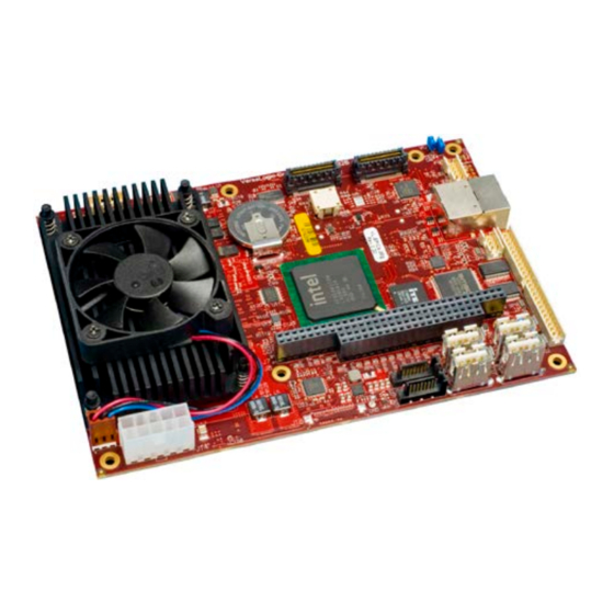
- Page 1 Reference Manual REV. November 2020 VL-EPICs-36 (Komodo) Intel Core 2 Duo Based SBC with Ethernet, Video, SUMIT and PC/104 interface...
- Page 2 Copyright © 2014-2020 VersaLogic Corp. All rights reserved. Notice: Although every effort has been made to ensure this document is error-free, VersaLogic makes no representations or warranties with respect to this product and specifically disclaims any implied warranties of merchantability or fitness for any particular purpose.
- Page 3 Data sheets and manufacturers’ links for chips used in this product BIOS information and upgrades This is a private page for VL-EPICs-36 users that can be accessed only be entering this address directly. It cannot be reached from the VersaLogic homepage. VL-EPICs-36 Reference Manual...
-
Page 4: Table Of Contents
Contents Introduction ........................1 Description .......................... 1 Features and Construction ..................1 Technical Specifications ..................... 2 VL-EPICs-36 Block Diagram ..................... 3 Thermal Considerations ...................... 4 CPU Die Temperature ................... 4 Model Differences ....................4 RoHS Compliance ......................5 About RoHS ......................5 Warnings .......................... - Page 5 PS/2 Mouse and Keyboard Interface ................39 Push-Button Reset ......................39 Programmable and Power LEDs ..................40 Internal Speaker ........................ 40 MiniBlade Socket (J19) ....................41 SPX™ Expansion Bus (J22) ..................... 42 VersaLogic SPX Expansion Modules ..............42 VL-EPICs-36 Reference Manual...
- Page 6 Contents SPI Registers ......................43 Interrupt Configuration ....................46 Special Registers ......................48 Product Code Register ...................... 48 Revision Level Register ....................49 Special Control Register ....................50 Appendix A – References.................... 51 VL-EPICs-36 Reference Manual...
-
Page 7: Introduction
Two RS-232 and two RS-232/422/485 100BaseTX / 1000BaseT COM ports, 460K baud max. High speed 3D video accelerator (Gen Expansion with VersaLogic SPX add- 5.0) with analog and LVDS flat panel on I/O modules outputs EPIC-compliant 4.5” x 6.5” footprint... -
Page 8: Technical Specifications
Introduction Technical Specifications Specifications are typical at 25°C with 5.0V supply unless otherwise noted. Board Size: SPX: 4.5” x 6.5” (EPIC standard) Supports four external SPI chips of user design or any SPX™ series expansion board Storage Temperature: BIOS: -40° C to 85° C Phoenix Technologies Embedded BIOS with Operating Temperature: OEM enhancements... -
Page 9: Vl-Epics-36 Block Diagram
Introduction VL-EPICs-36 Block Diagram Figure 1. System Block Diagram VL-EPICs-36 Reference Manual... -
Page 10: Thermal Considerations
Intel does not warrant their CPUs in the event of this occurrence. ODEL IFFERENCES VersaLogic offers both standard and extended temperature models of the VL-EPM-35. The basic operating temperature specification for both models is shown below. VL-EPICs-36S: 0° C to +60° C free air, no airflow ... -
Page 11: Rohs Compliance
(PBDE) flame retardants, in certain electrical and electronic products sold in the European Union (EU) beginning July 1, 2006. VersaLogic Corporation is committed to supporting customers with high-quality products and services meeting the European Union’s RoHS directive. -
Page 12: Handling Care
Product Support web page below. The support page provides links to component datasheets, device drivers, and BIOS and PLD code updates. VL-EPICs-36 Product Page 6If you have further questions, contact VersaLogic Technical Support at (503) 747-2261. VersaLogic support engineers are also available via e-mail at Support@VersaLogic.com. EPAIR... - Page 13 Introduction Note: Please mark the RMA number clearly on the outside of the box before returning. VL-EPICs-36 Reference Manual...
-
Page 14: Configuration And Setup
SATA Hard Drive USB CD-ROM Drive DDR3 DRAM module The following VersaLogic cables are recommended. VL-CBR-2010, 2011, or 2012 – LVDS cable VL-CBR-0701 – SATA data cable VL-CBR-0401 – ATX to SATA power cable ... - Page 15 Configuration and Setup OS Installation USB CD- CD-ROM ROM Drive USB Keyboard USB Type A and USB Mouse USB Type A J12 J17 J11 J16 VL-CBR-0701 SATA J10 J15 Hard Drive VL-EPICs-36 KOMODO VL-CBR-0401 VL-CBR-2022 Power Supply VL-CBR-2010, 2011, or 2012 LVDS Figure 2.
-
Page 16: Operating System Installation
Configuration and Setup Attach an ATX to SATA cable VL-CBR-0401 to the ATX power supply and SATA drive. Attach a USB CD-ROM drive to any Type A USB connector on the board (J11, J12, J16, or J17). 3. Attach Power ... -
Page 17: Physical Details
Physical Details Dimensions and Mounting VL-EPIC -36 D IMENSIONS The VL-EPICs-36 complies with all PC/104-Express standards. Dimensions are given below to help with pre-production planning and layout. 6.096 5.596 5.496 2.596 2.446 Heatsink / fan mounting 3.250 1.950 0.000 -0.200 Figure 3.VL-EPICs-36 Dimensions and Mounting Holes (Not to scale. -
Page 18: Vl-Cbr-5009 Dimensions
Physical Details VL-CBR-5009 D IMENSIONS 5.50 5.10 1.575 1.875 1.95 1.175 1.325 0.065 Figure 4. VL-CBR-5009 Dimensions and Mounting Holes (Not to scale. All dimensions in inches.) VL-EPICs-36 Reference Manual... -
Page 19: Hardware Assembly
Physical Details ARDWARE SSEMBLY The VL-EPICs-36 uses pass-through SUMIT (PCIe) and PC/104 (ISA) connectors so that expansion modules can be added to the top of the stack. A SUMIT expansion module with a PCIe x4 lane must be closest to the CPU board. Next on the stack would be an expansion module with a PCIe x1 lane. -
Page 20: External Connectors
Physical Details External Connectors VL-EPIC -36 C – T ONNECTOR OCATIONS Ethernet LED Ethernet User I/O J12 - USB3 Audio J17 - USB2 J24 - Factory J7-J8 SUMIT A (PCIe) J11 - USB1 PC/104 (ISA) J16 - USB0 J10 - SATA1 J15 - SATA0 SUMIT B (PCIe) J10 J15... -
Page 21: Vl-Epics-36 Connector Locations - Bottom
Physical Details VL-EPIC -36 C – B ONNECTOR OCATIONS OTTOM eUSB MiniBlade SO-DIMM LVDS Figure 7. Connector Locations (Bottom) VL-EPICs-36 Reference Manual... -
Page 22: Vl-Epics-36 Connector Functions And Interface Cables
Physical Details VL-EPIC -36 C ONNECTOR UNCTIONS AND NTERFACE ABLES Table 1 provides information about the function, mating connectors, and transition cables for VL-EPICs-36 connectors. Page numbers indicate where a detailed pinout or further information is available. Table 1: Connector Functions and Interface Cables Transition Pin 1 Location Connector... -
Page 23: Connector Locations - Vl-Cbr-5009
Physical Details – VL-CBR-5009 ONNECTOR OCATIONS Soft Reset Button Breakout Board Adapter PS/2 Mouse (Top) Keyboard (Bottom) Speaker COM4 COM3 COM1 (Top) COM2 (Bottom) Power (Top) PLED (Bottom) Reset = Pin 1 Figure 8. VL-CBR-5009 Connector Locations VL-CBR-5009 C ONNECTOR UNCTIONS Table 2: VL-CBR-5009 Connector Functions and Interface Cables Connector /... -
Page 24: Jumper Blocks
Physical Details Jumper Blocks UMPERS HIPPED ONFIGURATION Figure 9. Jumper Block Locations VL-EPICs-36 Reference Manual... -
Page 25: Jumper Summary
Page V1[1-2] System BIOS Selector In – Secondary BIOS selected Out – Primary BIOS selected The system BIOS is field-upgradeable using the BIOS upgrade utility. www.VersaLogic.com/private/komodosupport.asp for more information. V2[1-2-3] V2[1-2] In CMOS RAM and Real Time Clock Erase [1-2] In – Normal [2-3] In –... -
Page 26: System Features
System Features Power Supply OWER ONNECTORS Main power is applied to the VL-EPICs-36 through an EPIC-style 10-pin polarized connector at location J14. Warning! To prevent severe and possibly irreparable damage to the system, it is critical that the power connectors are wired correctly. Make sure to use both +5VDC pins and all ground pins to prevent excess voltage drop. -
Page 27: Power Delivery Considerations
A good power delivery method eliminates such problems as voltage drop and lead inductance. Using the VersaLogic approved power supply (VL-PS200-ATX) and power cable (VL-CBR-2022) will ensure high quality power delivery to the board. -
Page 28: Cpu
TATE RIVE The VersaLogic VL-MF7 Series modules provide 1 or 2 GB of RAM plus 8 GB of flash storage. The solid state drive (SSD) can function as a bootable SATA drive or secondary storage device without claiming either of the SATA channels at connectors J10 or J15. -
Page 29: Default Cmos Ram Setup Values
System Features Warning! If CMOS Setup default settings make the system unbootable and prevent the user from entering CMOS Setup, the system can be recovered by switching to the backup BIOS. CMOS RAM S EFAULT ETUP ALUES After CMOS RAM is cleared, the system will load default CMOS RAM parameters the next time the board is powered on. -
Page 30: Fan/Tachometer Monitor
System Features Fan/Tachometer Monitor The Super I/O chip on the VL-EPICs-36 contains a hardware monitor which includes a 16-bit fan tachometer register that can be read to obtain the speed of the fan on the VL-EPICs-36. When one byte of the 16-bit register is read, the other byte latches the current value until it is read, in order to ensure a valid reading. - Page 31 System Features while (keypressed != ESC) (kbhit()) keypressed = getch(); Read FanTach1 LSB first, latches MSB. outp( Bindex, FANTACHREG //Fantach 1 LSB FTraw = inp( Bdata outp( Bindex, FANTACHREG //Fantach 1 MSB FTraw += inp( Bdata ) << 8; /* FTraw now contains the number of 90KHz pulses it took to find 5 tach edges. (5 edges = 2 tach pulses = 1 revolution) Convert Raw to RPMs...
-
Page 32: Interfaces And Connectors
Interfaces and Connectors Video Output (J1 SVGA, J20 LVDS) An on-board video controller integrated into the chipset provides high performance video output for the VL-EPICs-36. The controller supports dual, simultaneous, independent video output. ONFIGURATION The video interface uses PCI interrupt INTA#. CMOS Setup is used to select the IRQ line routed to INTA#. -
Page 33: Lvds Flat Panel Display Connector (J20)
CMOS Setup provides several options for standard LVDS flat panel types. If these options do not match the requirements of the panel you are attempting to use, contact Support@VersaLogic.com for a custom video BIOS. The 3.3V power provided to pins 19 and 20 of J20 is protected by a 1 Amp fuse. -
Page 34: Compatible Lvds Panel Displays
Interfaces and Connectors LVDS P OMPATIBLE ANEL ISPLAYS The following flat panel displays are reported to work properly with the integrated graphics video controller chip used on the VL-EPICs-36. Table 7: Compatible Flat Panel Displays Panel Panel Manufacturer Model Number Size Resolution Interface... -
Page 35: Pci Express / Sumit Connectors (J2-J3)
Interfaces and Connectors PCI Express / SUMIT Connectors (J2-J3) The SUMIT A and B connectors (J3 and J2, respectively) provide a subset of the PCI Express functionality, as shown in Table 8 and Table 9. See the SUMIT Specification for a complete description of the SUMIT interface. - Page 36 Interfaces and Connectors Table 9: SUMIT B Connector Pinout Pin Signal Name Function Pin Signal Name Function Ground Ground B_PETp0 Link B, lane 0 transmit + B_PERp0 Link B, lane 0 receive + B_PETn0 Link B, lane 0 transmit – B_PERn0 Link B, lane 0 receive –...
-
Page 37: Ethernet (Interface J5, Led J4)
Interfaces and Connectors Ethernet (Interface J5, LED J4) The VL-EPICs-36 features an on-board Intel 82574IT Gigabit Ethernet controller, which provides a standard IEEE 802.3 Ethernet interface for 1000Base-T, 100Base-TX, and 10Base-T applications. The 82574IT provides one PCIe lane with sufficient bandwidth to support a 2.5 gigabits per second (GB/s) transfer rate. -
Page 38: Audio (J6)
Interfaces and Connectors Audio (J6) The audio interface on the VL-EPICs-36 is implemented using the IDT 92HD75B Audio Codec. This interface is compatible with Intel’s High Definition (HD) Audio Interface and is Microsoft WLP 3/4 premium logo compliant, as defined in WLP 3.09. Drivers are available for most Windows-based operating systems. -
Page 39: Pc/104 (Isa) Expansion Bus (J7-J8)
Interfaces and Connectors PC/104 (ISA) Expansion Bus (J7-J8) VL-EPICs-36 has limited support of the PC/104 bus. Most PC/104 cards will work, but be sure to check the requirements of your PC/104 card against the list below. PC/104 I/O S UPPORT The ISA I/O ranges listed below are supported. -
Page 40: Sata Interface (J10, J15)
Interfaces and Connectors SATA Interface (J10, J15) The VL-EPICs-36 provides two serial ATA (SATA) ports, which communicate at a rate of up to 3.0 GB/s (SATA 2). The SATA connectors at locations J10 and J15 are standard 7-pin straight SATA connectors with friction latching. Power to SATA drives is supplied by the ATX power supply. -
Page 41: Bios Configuration
PCI interrupt line. USB I (J23) NTERFACE The VL-EPICs-36 includes one eUSB port, as shown below. The VersaLogic VL-F15 Series of eUSB SSD modules are available in sizes of 2 MB or 4 MB. Contact VersaLogic Sales to order. -
Page 42: Main I/O Connector (J13)
Interfaces and Connectors Main I/O Connector (J13) The 50-pin I/O connector (J13) incorporates the COM ports, PS/2 keyboard and mouse, programmable LED, reset button, soft power reset, and speaker interfaces. Table 15 illustrates the function of each pin. The 5.0V power lines provided to J13 are protected by a 1 Amp fuse. Table 15: I/O Connector Pinout VL-CBR-5009 VL-CBR-5009... -
Page 43: Serial Ports
Interfaces and Connectors Serial Ports The VL-EPICs-36 features four on-board 16550-based serial channels located at standard PC I/O addresses. COM1 and COM2 are RS-232 (115.2K baud) serial ports. IRQ lines are chosen in CMOS Setup. COM ports can share interrupts with other COM ports, but not with other devices. COM3 and COM4 can be operated in RS-232 4-wire, RS-422 or RS-485 modes. -
Page 44: Serial Port Connectors
Interfaces and Connectors ERIAL ONNECTORS The pinouts of the DB9M connectors apply to the serial connectors on the VersaLogic breakout board VL-CBR-5009. These connectors use IEC 61000-4-2-rated TVS components to help protect against ESD damage. Table 16: COM1-2 Pinout – VL-CBR-5009 Connector J3... -
Page 45: Ps/2 Mouse And Keyboard Interface
A standard PS/2 keyboard and mouse interface is accessible through connector J4 of the VersaLogic breakout board, VL-CBR-5009. The breakout board is connected to connector J13 of the VL-EPICs-36. The 5V power provided to the keyboard and mouse is protected by a 1 Amp fuse. -
Page 46: Programmable And Power Leds
Interfaces and Connectors Programmable and Power LEDs Connector J13 includes an output signal for attaching a software controlled LED. Connect the cathode of the LED to J13 pin 48; connect the anode to +5V. An on-board resistor limits the current to 15 mA when the circuit is turned on. A programmable LED is provided on the VL-CBR-5009 breakout board. -
Page 47: Miniblade Socket (J19)
SATA port. See the MiniBlade Specification for more information. The VL-F23 series of MiniBlade devices are available from VersaLogic in sizes of 1 MB, 2 MB, and 4 MB. Contact VersaLogic Sales to order. Table 19: MiniBlade Socket Pinout... -
Page 48: Spx™ Expansion Bus (J22)
XPANSION ODULES VersaLogic offers a number of SPX modules that provide a variety of standard functions, such as analog input, digital I/O, CANbus controller, and others. These are small boards (1.2” x 3.775”) that can mount on the PC/104 stack, using standard PC/104 stand-offs, or up to two feet away Info@VersaLogic.com... -
Page 49: Spi Registers
Interfaces and Connectors SPI R EGISTERS A set of control and data registers are available for SPI transactions. The following tables describe the SPI control registers (SPICONTROL and SPISTATUS) and data registers (SPIDATA3-0). SPICONTROL (READ/WRITE) CA8h (or C98h) CPOL CPHA SPILEN1 SPILEN0 MAN_SS... - Page 50 Interfaces and Connectors SPISTATUS (READ/WRITE) CA9h (or C99h) IRQSEL1 IRQSEL0 SPICLK1 SPICLK0 HW_IRQ_EN LSBIT_1ST HW_INT BUSY Table 22: SPI Control Register 2 Bit assignments Mnemonic Description D7-D6 IRQSEL IRQ Select – These bits select which IRQ will be asserted when a hardware interrupt from a connected SPI device occurs.
- Page 51 Interfaces and Connectors SPIDATA0 (READ/WRITE) CAAh (or C9Ah) MSbit LSbit SPIDATA1 (READ/WRITE) CABh (or C9Bh) MSbit LSbit SPIDATA2 (READ/WRITE) CACh (or C9Ch) MSbit LSbit SPIDATA3 (READ/WRITE) CADh (or C9Dh) MSbit LSbit SPIDATA3 contains the most significant byte (MSB) of the SPI data word. A write to this register will initiate the SPI clock and, if the MAN_SS bit = 0, will also assert a slave select to begin an SPI bus transaction.
-
Page 52: Interrupt Configuration
Interrupt Configuration The VL-EPICs-36 has the standard complement of PC-type interrupts. Up to eight IRQ lines can be allocated as needed to PCI devices. There are no interrupt configuration jumpers. All configuration is handled through CMOS Setup. Table 23: Interrupt Configuration ... - Page 53 Interfaces and Connectors Table 24: PCI Interrupt Settings PCI Interrupts Source INTA# INTB# INTC# INTD# INTE# INTF# INTG# INTH# VGA Display High Definition Audio PCIe Port 1 PCIe Port 2 USB UHCI Port 1 USB UHCI Port 2 ...
-
Page 54: Special Registers
Special Registers Product Code Register PRODCODE (Read/Write) CA0h (or C90h) PLED Table 25: Product Code Register Bit Assignments Mnemonic Description PLED Light Emitting Diode — Controls the programmable LED on connector J13. 0 = Turns LED on 1 = Turns LED off D6-D0 Product Code —... -
Page 55: Revision Level Register
Mnemonic Description D7-D3 FPGA Revision Level — These bits are hard-coded to represent the FPGA revision. Contact VersaLogic Support for further information. These bits are read-only. Extended Temperature — Indicates operating temperature range. 0 = Standard temperature range 1 = Extended temperature range This bit is read-only. -
Page 56: Special Control Register
Special Registers Special Control Register SCR (Read/Write) CA2h (or C92h) BIOS_JMP BIOS_OR BIOS_SEL Reserved Reserved Reserved Reserved Reserved Table 27: Special Control Register Bit Assignments Mnemonic Description BIOS_JMP System BIOS Selector Jumper Status — Indicates the status of the system BIOS selector jumper at V1[1-2]. -
Page 57: Appendix A - References
Appendix A – References Intel Core 2 Duo Intel Core 2 Duo Datasheet Chipset Intel GM45 Mobile Intel 4 Series Chipset Datasheet Ethernet Controller Intel 82574IT Ethernet Controller Intel 8257IT Datasheet PC/104 Interface PC/104 Specification SUMIT Interface SUMIT Specification General PC Documentation The Programmer’s PC Sourcebook Amazon.com General PC Documentation...
Need help?
Do you have a question about the Komodo VL-EPICs-36 and is the answer not in the manual?
Questions and answers