Table of Contents
Advertisement
Quick Links
Advertisement
Table of Contents

Subscribe to Our Youtube Channel
Related Manuals for VersaLogic BayCat VL-EPM-31ECP


Summary of Contents for VersaLogic BayCat VL-EPM-31ECP
- Page 1 Hardware Reference Manual REV. April 2018 BayCat (VL-EPM-31) Intel Atom™-based Single ® Board Computer with Dual Ethernet, Video, USB, SATA, Serial I/O, Digital I/O, Trusted Platform Module security, Counter/Timers, Mini PCIe, mSATA, PCI/104-Plus Interface, and SPX.
- Page 2 Copyright © 2016-2018 VersaLogic Corp. All rights reserved. Notice: Although every effort has been made to ensure this document is error-free, VersaLogic makes no representations or warranties with respect to this product and specifically disclaims any implied warranties of merchantability or fitness for any particular purpose.
- Page 3 It cannot be reached from the VersaLogic homepage. VersaTech KnowledgeBase is an invaluable resource for resolving technical issues with your VersaLogic product. If you have additional questions, contact VersaLogic Technical Support at (503) 747-2261. VersaLogic support engineers are also available via e-mail at Support@VersaLogic.com. EPAIR ERVICE If your product requires service, you must obtain a Returned Material Authorization (RMA) number by calling (503) 747-2261.
- Page 4 The return shipping address EPM-31 Hardware Reference Manual...
- Page 5 (PBDE) flame retardants, in certain electrical and electronic products sold in the European Union (EU) beginning July 1, 2006. VersaLogic Corporation is committed to supporting customers with high-quality products and services meeting the European Union’s RoHS directive.
- Page 6 OUNTING UPPORT The single board computer must be supported at all four mounting points to prevent excessive flexing when expansion modules are attached and removed. Flex damage caused by excessive force on an improperly mounted circuit board is not covered under the product warranty. See page 15 for more details.
-
Page 7: Table Of Contents
Contents Introduction ......................... 11 Description ........................11 Technical Specifications ....................13 Thermal Considerations ....................13 EPM-31 Block Diagram ....................14 Dimensions and Mounting ....................15 Hardware Assembly ..................... 16 Related Documents ......................16 Configuration and Setup ..................... 17 Initial Configuration ......................17 Basic Setup ........................ - Page 8 On-Board Ethernet Status LEDs ................52 Expansion Interfaces ....................53 SPX™ Expansion Bus ...................... 53 Cabling ......................... 54 VersaLogic SPX Expansion Modules ..............54 PC/104-Plus Expansion Bus ..................... 55 ISA Bus (on PC/104-Plus and PC/104 Expansion Modules) ......55 ISA I/O Support ....................56 ISA Memory Support ...................
- Page 9 Heat Sink Only Considerations: ................70 Heat Sink with Fan Considerations: ..............70 EPM-31 Thermal Characterization ................... 71 Test Results......................72 Installing the VersaLogic Thermal Solutions ..............75 Installing the Passive Heat Sink ................75 Installing the Heat Sink Fan ................76 Figures Figure 1.
- Page 10 Contents Figure 17. Location of PCIe Mini Card LEDs ..............37 Figure 18. Location and Pin Orientation of User I/O Connector ........38 Figure 19. Location and Pin Orientation of Digital I/O Connector ........40 Figure 20. Location and Pin Orientation of Serial Port Connector ........43 Figure 21.
- Page 11 Contents Table 18: Available ISA Bus I/O Ranges ................. 56 Table 19: User I/O Connector Pinout ................60 Table 20: Auxiliary I/O Connector Pinout ................ 62 Table 21: Main I/O Connector Pinout................65 Table 22: CPU Thermal Trip Points ................. 69 Table 23: Temperature Monitoring Programs ..............
-
Page 12: Introduction
Introduction Description The EPM-31 BayCat is a feature-packed single board computer (SBC) designed to support OEM applications where high reliability and long-term availability are required. Its features include: † † Intel Atom “Bay Trail” processor, Trusted Platform Module quad, dual, or single core with ... -
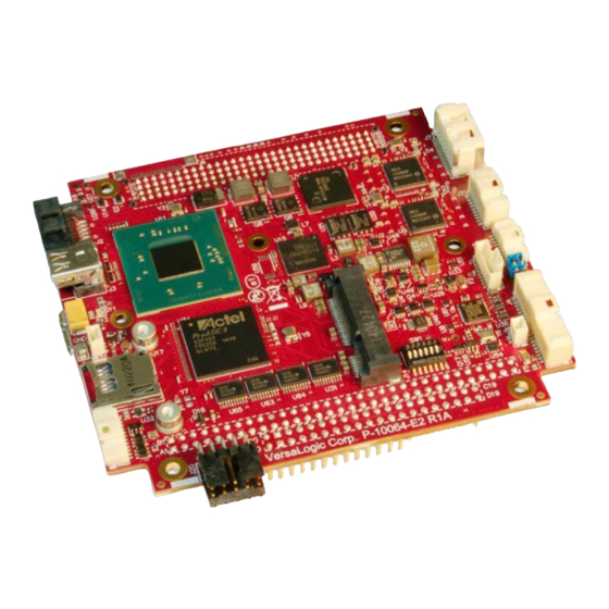
Page 13: Figure 2. Vl-Epm-31 Baycat Single Board Computer (Top Side)
Introduction Item/ Item/ [Reference Description [Reference Description Designator] Designator] Intel Atom “Bay Trail” SoC J [J14] PCIe Minicard/mSATA connector B [J7] Ethernet port 0/1 connector FPGA device C [J21] Digital I/O connector L [J20] Main power connector D [J13] COM1/COM2 Serial port connector M [J5] VGA connector E [J19]... -
Page 14: Technical Specifications
Introduction Item/ [Reference Description Designator] A [J11] PC/104 Legacy PCI expansion connector Trusted Platform Module (TPM) device C [J16] USB 3.0 port D [J9] SODIMM socket E [J10A/J10B] PC/104 Legacy ISA expansion connector Ethernet transformers Figure 3. VL-EPM-31 BayCat Single Board Computer (Bottom Side) Technical Specifications See the BayCat Data Sheet... -
Page 15: Epm-31 Block Diagram
Introduction EPM-31 Block Diagram Figure 4. EPM-31 Block Diagram EPM-31 Hardware Reference Manual... -
Page 16: Dimensions And Mounting
Introduction Dimensions and Mounting The EPM-31 complies with the PC/104 standard which provides for specific mounting hole and PC/104-Plus stack locations as shown in Figure 5. Figure 5. EPM-31 Dimensions and Mounting Holes (Not to scale. All dimensions in inches.) CAUTION: The EPM 31 must be supported at all four mounting points to prevent... -
Page 17: Hardware Assembly
BIOS Setup utility. All BIOS menus, submenus, and configuration options are described. VersaAPI Installation and Reference Guide – describes the shared library of API calls for reading and controlling on-board devices on certain VersaLogic products. Additional documents: Processor Intel Atom E38xx (formerly Intel Atom Processor E3800 Product Family Datasheet “Bay Trail”) System-on-Chip... -
Page 18: Configuration And Setup
VGA video monitor USB Keyboard USB Mouse SATA hard drive The following VersaLogic cables and accessories are recommended. VGA Video adapter cable (CBR-1204) User I/O cable (CBR-4005) and accompanying paddleboard (CBR-4005B) Power adapter cable (CBR-1008) ... - Page 19 Configuration and Setup 1. Install Memory Insert the DDR3L DRAM module into the SO-DIMM socket on the bottom side of the board and latch it into place. 2. Attach Cables and Peripherals Note: The instructions below refer to connector locations by the reference designators printed on the board’s silkscreen.
-
Page 20: Jumper Blocks
Configuration and Setup Jumper Blocks UMPERS LOCKS IN THE HIPPED ONFIGURATION Figure 6. Jumper Block Locations UMPER UMMARY Table 1: Jumper Summary Jumper Block Description Reference COM1 Rx End-point termination • V1 [1-2] Table 11, page 45 In – COM1 terminator enabled for RS-485/RS-422 •... -
Page 21: Configuration Switches
Configuration and Setup Configuration Switches Figure 7 shows the as-shipped switch configuration with all switches in the Off position. The Off position is toward the center of the board. Figure 7. Location of SW1 Configuration Switch Block Table 2: Switch Setting Summary SW1 Switch Description Position... -
Page 22: Resetting The Bios To Factory Defaults
Configuration and Setup Integrator’s Note: If a battery is installed (on the CBR-4005B paddleboard or externally using the J8 connector), switch position 2 must be set to the Off position. If it is set to On, the battery will discharge quickly. -
Page 23: Operating System Installation
The operating systems listed on the VersaLogic OS Compatibility Chart use the standard installation procedures provided by the maker of the OS. Special optimized hardware drivers for a particular operating system, or a... -
Page 24: Board Features
Voltage 1.35 V Type DDR3L (VersaLogic VL-MM9 Series modules) I/O Interfaces The EPM-31 board’s I/O interfaces and their associated connectors are described in later chapters as follows: Mass Storage Interfaces (SATA and microSD), beginning on page 31 ... -
Page 25: Power Delivery
Board Features Power Delivery OWER ONNECTOR Figure 8 shows the location and pin orientation of the main power connector. Figure 8. Location and Pin Orientation of the Main Power Connector CAUTION: To prevent severe and possibly irreparable damage to the system, it is critical that the power connector is wired correctly. -
Page 26: Cabling
ELIVERY ONSIDERATIONS Using the VersaLogic approved power supply (VL-PS200-ATX) and power cable (VL-CBR- 1008) ensures high quality power delivery to the board. Customers who design their own power delivery methods should take into consideration the guidelines below to ensure good power connections. -
Page 27: Power Button
Board Features OWER UTTON User I/O connector J4 includes an input for a push-button power switch. Shorting J4, pin 17 to ground causes the board to enter an S5 power state (similar to the Windows Shutdown state). Shorting it again returns the board to the S0 power state and reboots the board. The button can be configured in Windows to enter an S3 power state (Sleep, Standby, or Suspend-to-RAM), an S4 power state (Hibernate or Suspend-to-Disk), or an S5 power state (Shutdown or Soft-Off). -
Page 28: Battery Power Options
Board Features ATTERY OWER PTIONS The battery circuit on the EPM-31 provides power for the Real-Time Clock (RTC) and power to store BIOS Setup utility settings in non-volatile RAM. The EPM-31 has multiple options for providing battery power: Use an external battery, connected to the board through the J8 external battery connector. ... -
Page 29: Vl-Cbr-0203 External Battery Module
ODULE The VL-CBR-0203 external battery module is compatible with the EPM-31. For more information, contact Sales@VersaLogic.com Figure 10. VL-CBR-0203 Latching Battery Module Real Time Clock (RTC) The EPM-31 features a real-time clock/calendar (RTC) circuit. The RTC can be set using the BIOS Setup utility. -
Page 30: Leds/Indicators
Board Features LEDs/Indicators Figure 11 shows the locations of the boards LEDs/indicators. Description For more information, see… Ethernet Port 0 status LED Table 15, page 52 Ethernet Port 1 status LED Table 15, page 52 D9/D8 PCIe Mini Card LEDs Table 7, page 37 SATA/mSATA Activity LED Figure 16, page 36... -
Page 31: Power Leds
Board Features OWER Figure 12 shows the location of the dual green/yellow LED. This dual LED indicates the following: The green LED illuminates when all power rails are within specified limits and indicates that the board is in the S0 power state. If any power rail is not within specified limits, the green LED will not illuminate. -
Page 32: Mass Storage Interfaces
Mass Storage Interfaces SATA The EPM-31 provides one 3 GB/s SATA port (J2). The SATA connector is a standard 7-pin right-angle connector with latching capability. Power to the SATA drive is provided by the ATX power supply. Note that the standard SATA drive power connector is different from the typical 4-pin Molex connector used on IDE drives. -
Page 33: Microsd Socket
Mass Storage Interfaces microSD Socket Figure 14 shows the location of the microSD socket. The VL-F41 series of microSD cards provide solid-state storage of 2 GB, 4 GB, or 8 GB. The microSD socket accommodates cards with up to 32 GB of storage capacity. No drivers are needed, as the device interface is abstracted as a standard parallel IDE drive on the master IDE channel. -
Page 34: Multi-Purpose I/O
Multi-purpose I/O USB Interfaces The EPM-31 includes four USB 2.0 host ports and one USB 3.0 host port. The four USB 2.0 ports are incorporated into the J4 user I/O connector, with standard USB Type A connectors located on the VL-CBR-4005B paddleboard. Connector J16 on the bottom side of the board provides a USB 3.0 Micro-A (host) connector. -
Page 35: Cabling
Note: This signal is typically used for On-The-Go (OTG) mode. The BayCat does not support this mode. ABLING The VersaLogic VL-CBR-1015 cable is a USB 3.0 Micro-A to Micro-B adapter. The VL-CBR- 1015 cable can be used to connect the BayCat to any certified USB 3.0 hubs. - Page 36 Multi-purpose I/O PCIe Mini Card PCIe Mini Card mSATA mSATA Signal Name Function Signal Name Function Not connected Reserved Not connected REFCLK+ Reference clock input + Reserved Not connected Not connected Reserved Not connected Ground Ground Not connected Reserved Not connected Not connected Reserved Not connected...
-
Page 37: Msata Activity Led
Multi-purpose I/O SATA A CTIVITY Figure 16 shows the location (D12) of the SATA/mSATA activity blue LED. This LED indicates activity on either the SATA or the mSATA interface. Not all mSATA drives provide this disk activity signal. Figure 16. Location of the SATA/mSATA Activity LED EPM-31 Hardware Reference Manual... -
Page 38: Pcie Mini Card Leds
Multi-purpose I/O Two dual-colored PCIe Mini Card LEDs are provided on the EPM-31 at locations D9 and D8. Table 7 lists the states of the LEDs. Figure 17 shows the location of the PCIe Mini Card LEDs. Table 7: PCIe Mini Card LED States Color Status (when lit) Green... -
Page 39: User I/O Connector
Multi-purpose I/O User I/O Connector The 40-pin J4 I/O connector incorporates the signals for the following: Four USB ports Eight GPIO lines (these are functionally muxed with six timer I/O signals per FPGA registers). There are eight timer signals and they share digital I/Os 16-9. The eight GPIO lines on the paddleboard each have an alternate mode, accessible using the FPGA’s AUXMOD1 register. -
Page 40: Cabling
Multi-purpose I/O Table 8 provides the pinout of the user I/O connector. Table 8: J4 I/O Connector Pinout and Pin Orientation Signal Signal +5 V USB0_P USB1_P USB0_N USB1_N USB2_P USB3_P USB2_N USB3_N +3.3 V (Note 1) SPKR# PLED# PWR_BTN# RST_BTN# I2C Clock V_BATT... -
Page 41: Digital I/O (Dio)
40 kΩ. After reset, the DIO lines are set as inputs with pull-ups that will be detected as a HIGH state to external equipment. VersaLogic provides a set of application programming interface (API) calls for managing the DIO lines. See the for information. -
Page 42: Dio Guidelines
Multi-purpose I/O Table 9: J21 I/O Connector Pinout VL-CBR-2004B Terminal Block J21 Pin Signal Terminal Block Digital I/O 1 Digital I/O 2 Digital I/O 3 Digital I/O 4 Ground Digital I/O 5 Digital I/O 6 Digital I/O 7 Digital I/O 8 Ground Digital I/O 9 (Optional Timer Channel 5 output) -
Page 43: Power States
Multi-purpose I/O OWER TATES CPU power states will affect voltage rails driving DIO circuits as described below: DIOs and their pull-up resistors will remain powered in all CPU power states (except when power is turned off). The DIO power (which includes the pullup voltage) can be controlled (the same power used for the 8x GPIOs on the CBR-4005 paddleboard) using an FPGA register setting. -
Page 44: Serial Ports
Serial Ports The EPM-31 features two on-board 16550-based serial communications channels located at standard PC I/O addresses. The serial ports can be operated in RS-232 4-wire, RS-422, or RS-485 modes. IRQ lines are chosen in the BIOS Setup utility. Each COM port can be independently enabled, disabled, or assigned a different I/O base address in the BIOS setup utility. -
Page 45: Serial Port Connector Pinouts
Serial Ports ERIAL ONNECTOR INOUTS Table 10: J13 COM1/COM2 Connector Pinout RS-232 Signal RS-422/RS-485 Signal Port RTS1 TXD1_P TXD1# TXD1_N COM1 CTS1 RXD1_P RXD1# RXD1_N — RTS2 TXD2_P TXD2# TXD2_N COM2 CTS2 RXD2_P RXD2# RXD2_N — ABLING An adapter cable, part number CBR-1014, is available for routing the J13 signals to 9-pin D-sub connectors. -
Page 46: Com1/Com2 Hardware Configuration
Serial Ports COM1/COM2 Hardware Configuration Jumper block V1[1-2] enables the RS-422/485 termination resistor for COM1. Jumper V1[3-4] enables the RS-422/485 termination resistor for COM2. The termination resistor should be enabled for an RS-422 or RS-485 endpoint station; it should be disabled for RS-232 and RS-485 non-endpoint receivers. -
Page 47: Video Interfaces
Video Interfaces The EPM-31 incorporates the Intel Gen-7 graphics core with four Execution Units and Turbo Boost. It supports two independent displays. It also supported formats including DirectX 11, OpenGL 3, VP8, MPEG2, H.264, VC1, 2 HD streams (1080p@30fps), Flash and WMP support. The analog (VGA) and Mini DisplayPort video interfaces support Extended Desktop, Clone, and Twin display modes. -
Page 48: Cabling
Video Interfaces Table 12 lists the signals of the VGA video output connector. Table 12: J5 VGA Video Output Pinout Signal (Function) DB-15 Pin Ground RED (Red video) Ground GREEN (Green video) Ground BLUE (Blue video) Ground HSYNC (Horizontal sync) Ground VSYNC (Vertical sync) CRT_SCL (DDC data clock line) -
Page 49: Mini Displayport Connector
Video Interfaces Mini DisplayPort Connector DisplayPort consists of three interfaces: Main Link – transfers high-speed isochronous video and audio data Auxiliary channel – used for link management and device control; the EDID is read over this interface Hot Plug Detect –... -
Page 50: Console Redirection
Video Interfaces Table 13: J3 Mini DisplayPort Connector Pinout Signal Signal HOT PLUG DETECT ML_LANE0_P CONFIG 1 ML_LANE0_N CONFIG 2 ML_LANE1_P ML_LANE3_P ML_LANE1_N ML_LANE3_N ML_LANE2_P AUX_CH_P ML_LANE2_N AUX_CH_N DP_POWER Console Redirection The EPM-31 can be configured for remote access by redirecting the console to a serial communications port. -
Page 51: Network Interfaces
Network Interfaces The EPM-31 provides two on-board Intel I210-IT Gigabit Ethernet controllers. The controllers provide a standard Ethernet interface for 1000Base-T, 100Base-TX, and 10Base-T applications. The I210-IT Ethernet controller auto-negotiates connection speed. Drivers are available to support a variety of operating systems. THERNET ONNECTOR The J7 connector provides access to the Ethernet ports 0 and 1. -
Page 52: Cabling
Network Interfaces Table 14 lists the pinout of the Ethernet connector. Table 14: Ethernet Connector Pinout 10/100/1000 10/100/1000 10/100 Signals 10/100 Signals Signals Signals - Auto Switch (Tx or Rx) BI_DD- + Auto Switch (Tx or Rx) BI_DD+ - Auto Switch (Tx or Rx) BI_DB- + Auto Switch (Tx or Rx) BI_DB+... -
Page 53: On-Board Ethernet Status Leds
Network Interfaces OARD THERNET TATUS On-board status LEDs are provided for both Ethernet ports: D5 (green LED) provides status for Ethernet port 0 D2 (green LED) provides status for Ethernet port 1 Figure 25. Location of Ethernet Status LEDs Table 15: Ethernet Status LEDs Ethernet Port State... -
Page 54: Expansion Interfaces
Expansion Interfaces SPX™ Expansion Bus Up to two serial peripheral expansion (SPX) devices can be attached to the EPM-31 at connector J19 using a CBR-0901 cable. The SPX interface provides the standard serial peripheral interface (SPI) signals: CLK, MISO, and MOSI, as well as two chip selects, SS0# and SS1#. The +5 V power provided to pin 1 of the SPX connector is protected by a 1 A resettable fuse. -
Page 55: Cabling
XPANSION ODULES VersaLogic offers several SPX modules that provide a variety of standard functions, such as analog input, digital I/O, CANbus controller, and others. These are small boards (1.2 inches x 3.775 inches) that can mount on the PC/104 and PC/104-Plus stack, using standard PC/104 stand-offs, or up to two feet away from the base board. -
Page 56: Pc/104-Plus Expansion Bus
Expansion Interfaces PC/104-Plus Expansion Bus The EPM-31 provides a legacy stack-down PCI connector at locations J11 (for PCI) and J10 (for ISA) on the bottom side of the board for PC/104-Plus (PCI +ISA) as well as PCI-104 (PCI only) and PC/104 (ISA only) expansion modules. Figure 3 on shows the locations of these connectors. ... -
Page 57: Isa I/O Support
Expansion Interfaces Most PC/104-Plus (PCI +ISA) or PC/104 (ISA only) expansion modules will work, but be sure to check the requirements of your PC/104 card against the list above. ISA I/O S UPPORT Both 8-bit and 16-bit I/O cycles are supported, but for 16-bit cycles the PC/104 (ISA) module must be 16-bit capable and must assert IOCS16#. -
Page 58: Isa Irq Support
Expansion Interfaces ISA IRQ S UPPORT The following IRQs are supported on the ISA bus: IRQ3 IRQ9 IRQ4 IRQ10 IRQ5 IRQ11 IRQ6 IRQ12 IRQ7 IRQ15 Each of the IRQs must be enabled in the BIOS Setup utility before they can be used. (All are disabled by default.) Because ISA IRQ sharing is not supported, Some IRQs may not be available to the ISA bus due to operating system limitations. -
Page 59: System Resources And Maps
System Resources and Maps Refer to the EPM-31 Programmer’s Reference Manual for the following information: Memory map IRQ map I/O map FPGA register map FPGA register descriptions Programming information for certain hardware interfaces. EPM-31 Hardware Reference Manual... -
Page 60: Cbr-4005B Paddleboard
CBR-4005B Paddleboard CBR-4005B Paddleboard CBR-4005B C ONNECTORS AND NDICATORS Figure 31 shows the locations of the connectors, switches, and LEDs on the CBR-4005B paddleboard. Figure 27. CBR-4005B Connectors, Switches, and LEDs EPM-31 Hardware Reference Manual... -
Page 61: User I/O Connector
CBR-4005B Paddleboard I/O C ONNECTOR Figure 31 shows the location and pin orientation of the user I/O connector. Figure 28. Location and Pin Orientation of the User I/O Connector Table 19: User I/O Connector Pinout Signal Signal +5 V USB1_P USB2_P USB1_N USB2_N... -
Page 62: Cabling
CBR-4005B Paddleboard ABLING An adapter cable, part number CBR-4005A, is available for connecting the CBR-4005B paddleboard to the EPM-31. This is a 12-inch, Pico-Clasp 40-pin to 40-pin cable If your application requires a custom cable, the following information will be useful: CBR-4005B Board Connector Mating Connector Molex 501571-4007... -
Page 63: Auxiliary I/O Connector
CBR-4005B Paddleboard I/O C UXILIARY ONNECTOR Figure 31 shows the location and pin orientation of the auxiliary I/O connector. Figure 29. Location and Pin Orientation of Auxiliary I/O Connector Table 20: Auxiliary I/O Connector Pinout Signal Signal I2C Clock V_BATT I2C Data V_BATT_RETURN FPGA GPIO1... -
Page 64: Dimensions And Mounting Holes
CBR-4005B Paddleboard IMENSIONS AND OUNTING OLES Figure 30. CBR-4005B Dimensions and Mounting Holes EPM-31 Hardware Reference Manual... -
Page 65: Cbr-2004B Paddleboard
CBR-2004B Paddleboard To access the 16 digital I/O lines on the EPM-31 board, a paddleboard and 12-inch cable are available from VersaLogic, part number VL-CBR-2005. CBR-2004B Connectors Figure 31 shows the locations and pin orientations of the connectors on the CBR-2004B paddleboard. -
Page 66: Main I/O Connector
CBR-2004B Paddleboard I/O C ONNECTOR Figure 31 shows the location and pin orientation of the main I/O connector. Figure 33. Location and Pin Orientation of the Main I/O Connector Table 21: Main I/O Connector Pinout Signal Signal Digital I/O 1 Digital I/O 2 Digital I/O 3 Digital I/O 4... -
Page 67: Dimensions And Mounting Holes
CBR-2004B Paddleboard Dimensions and Mounting Holes Figure 34. CBR-2004B Dimensions and Mounting Holes EPM-31 Hardware Reference Manual... -
Page 68: Thermal Considerations
By itself, the heat plate is not a complete thermal solution. Integrators should either implement a thermal solution using the accessories available from VersaLogic or develop their own thermal solution that attaches to the heat plate, suitable for environments in which the EPM 31 will be used. -
Page 69: System-Level Considerations
Thermal Considerations YSTEM LEVEL ONSIDERATIONS The EPM-31 thermal solutions – either the HDW-412 heat sink alone or with the HDW-407 fan – are part of the larger thermal system of the application. Other PC/104 boards stacked under the BayCat and any other nearby heat sources (power supplies or other circuits), all contribute to how the EPM-31 will perform from a thermal standpoint. -
Page 70: Cpu Thermal Trip Points
Thermal Considerations CPU T HERMAL OINTS The CPU cores in the BayCat have their own thermal sensors. Coupled with these sensors are specific reactions to four thermal trip points. Table 22 describes the four thermal trip points. Table 22: CPU Thermal Trip Points Trip Point Description Active (Note 1) -
Page 71: Thermal Specifications, Restrictions, And Conditions
Due to the unknown nature of the entire thermal system, or the performance requirement of the application, VersaLogic cannot recommend a particular thermal solution. This information is provided for user guidance in the design of their overall thermal system solution. -
Page 72: Epm-31 Thermal Characterization
Table 25 describes the thermal testing setup for the board. Table 25: EPM-31 Thermal Testing Setup 31 (BayCat) single/dual/quad core CPU with: 4 GB of DDR3 DRAM (VersaLogic part number VL-MM9-4EBN) HDW-412 (passive heat sink) HDW-407 (heat sink fan) Hardware configuration ... -
Page 73: Test Results
Thermal Considerations ESULTS Test Scenario 1: Single Core EPM-31EAP + HDW-412 Heat Sink At 90% CPU utilization, this single core unit operates within the CPU’s core temperature safe operating range all the way up to +85 ºC using only a heat sink. Figure 35. - Page 74 Thermal Considerations Test Scenario 2: Dual Core EPM-31EBP + HDW-412 Heat Sink, with/without HDW- 407 fan As shown in Figure 36, running the test scenario with just the heat sink, the core temperature is slightly above 100 ºC at maximum ambient temperature. This will be less in most applications that require less than 90% CPU utilization.
- Page 75 Thermal Considerations Test Scenario 3: Quad Core EPM-31ECP + HDW-412 Heat Sink, with/without HDW-407 Fan As shown below, the quad core version of the BayCat will typically require a heat sink + fan for operation above 80 ºC, at >90% CPU utilization. Figure 37.
-
Page 76: Installing The Versalogic Thermal Solutions
Thermal Considerations Installing the VersaLogic Thermal Solutions The following thermal solution accessories are available from VersaLogic: VL-HDW-401 Thermal Compound Paste - used to mount the heat sink to the heat plate VL-HDW-412 Passive Heat Sink – mounts to standard product. -
Page 77: Installing The Heat Sink Fan
Thermal Considerations NSTALLING THE Install the heat sink fan (VL-HDW-407) using these steps: 1. Position the fan assembly Using Figure 39 as a guide, align the mounting holes of the heat sink fan with the four holes in the passive heat sink. Position the fan so that its power cable is on the side nearest the J24 CPU fan connector.
Need help?
Do you have a question about the BayCat VL-EPM-31ECP and is the answer not in the manual?
Questions and answers