
Related Manuals for VersaLogic Tiger


Summary of Contents for VersaLogic Tiger
- Page 1 Reference Manual DOC. REV. 4/3/2013 Tiger (VL-EPM-24) Intel Atom SBC with Ethernet, Video, USB, and PC/104-Plus interface...
- Page 2 Copyright © 2013 VersaLogic Corp. All rights reserved. Notice: Although every effort has been made to ensure this document is error-free, VersaLogic makes no representations or warranties with respect to this product and specifically disclaims any implied warranties of merchantability or fitness for any particular purpose.
- Page 3 Product Release Notes Rev 1.00 – Commercial release. Support Page The VL-EPM-24 support page, at http://www.versalogic.com/private/tigersupport.asp, contains additional information and resources for this product including: Reference Manual (PDF format) Operating system information and software drivers Data sheets and manufacturers’ links for chips used in this product ...
-
Page 4: Table Of Contents
Contents Introduction ........................1 Description .......................... 1 Features and Construction ..................1 Technical Specifications ..................... 2 VL-EPM-24 Block Diagram ....................3 RoHS Compliance ......................4 About RoHS ......................4 Warnings ..........................4 Electrostatic Discharge ..................4 Lithium Battery ...................... 4 Handling Care ...................... - Page 5 PC/104 Memory Cycle Support ................38 IRQ Support ......................38 DMA and Bus Master Support ................38 SPX Expansion Bus (J6) ....................39 VersaLogic SPX Expansion Modules ..............39 SPI Registers ......................40 System Resources and Maps ..................43 Memory Map ........................43...
- Page 6 Contents I/O Map ..........................43 Interrupt Configuration ..................... 44 Special Registers ......................45 PLED and Product ID Register ..................45 Revision and Type Register ....................46 GPI Jumper Register ......................47 Watchdog Timer Register ....................48 PC/104 I/O Block Enable Registers.................. 49 PC/104 Interrupt Request Enable Registers ..............
-
Page 7: Introduction
Introduction Description EATURES AND ONSTRUCTION The VL-EPM-24 is a feature-packed single board computer (SBC) designed for OEM control projects requiring fast processing and designed-in reliability and longevity (product lifespan). Its features include: Intel Atom processor Z530P, 1.6 GHz Seven USB 2.0 ports (one client and six 533 MT/s FSB (standard host) for keyboard, mouse, and other... -
Page 8: Technical Specifications
Introduction Technical Specifications Specifications are typical at +25°C with +5V supply unless otherwise noted. Board Size: Audio: 4.49” x 3.78” (PC/104 compliant) Intel High Definition Audio compatible, stereo line in/out Storage Temperature: SPX: -40° to +85°C Supports four external SPI chips of user design Operating Temperature: or any SPX series expansion board VL-EPM-24SU: 0°... -
Page 9: Vl-Epm-24 Block Diagram
Introduction VL-EPM-24 Block Diagram DDR2 DDR2 DDR2 DDR2 Intel SDRAM SDRAM SDRAM SDRAM Atom XL Processor DDR2 DDR2 DDR2 DDR2 SDRAM SDRAM SDRAM SDRAM PATA PATA / IDE DDR2 SO-DIMM Audio Line In/Out Intel HDA Intel HD Audio LVDS LVDS Video Codec Intel System Controller Hub... -
Page 10: Rohs Compliance
(PBDE) flame retardants, in certain electrical and electronic products sold in the European Union (EU) beginning July 1, 2006. VersaLogic Corp. is committed to supporting customers with high-quality products and services meeting the European Union’s RoHS directive. -
Page 11: Handling Care
Click the link below to see all KnowledgeBase articles related to the VL-EPM-24. VersaTech KnowledgeBase If you have further questions, contact VersaLogic Technical Support at (541) 485-8575. VersaLogic support engineers are also available via e-mail at Support@VersaLogic.com. VL-EPM-24 Reference Manual... -
Page 12: Repair Service
Introduction EPAIR ERVICE If your product requires service, you must obtain a Return Material Authorization (RMA) number by calling (541) 485-8575. Please provide the following information: Your name, the name of your company, your phone number, and e-mail address ... -
Page 13: Configuration And Setup
Inspect the system visually for any damage that may have occurred in shipping. Contact Support@VersaLogic.com immediately if any items are damaged or missing. Gather all the peripheral devices you plan to attach to the VL-EPM-24 and their interface and power cables. - Page 14 Configuration and Setup USB Keyboard and USB Mouse LVDS VL-EPM-24 TIGER VL-CBR- 5012 VL-CBR- 2012 or VL-CBR-2011 VL-CBR- 4406 Hard VL-CBR- 1008 Drive Power Supply CD-ROM OS Installation Drive CD-ROM Power to Drives Figure 2. Typical Start-up Configuration 1. Install Memory ...
- Page 15 Configuration and Setup Set the hard drive jumper for master device operation and the CD-ROM drive jumper for slave device operation. 3. Attach Power Plug the power adapter cable VL-CBR-1008 into socket J9. Attach the motherboard connector of the ATX power supply to the adapter. 4.
-
Page 16: Cmos Setup
Configuration and Setup CMOS Setup See VersaLogic Knowledgebase article VT1666 - VL-EPM-24 CMOS Setup Reference complete information on CMOS Setup parameters. Operating System Installation The standard PC architecture used on the VL-EPM-24 makes the installation and use of most of the standard x86-based operating systems very simple. -
Page 17: Physical Details
Physical Details Dimensions and Mounting VL-EPM-24 D IMENSIONS The VL-EPM-24 complies with PC/104-Plus dimensional standards. Dimensions are given below to help with pre-production planning and layout. 3.575 3.375 3.250 3.175 0.125 DIA x4 Use 3mm or #4 standoffs 0.11 0.200 0.125 0.000 -0.200... -
Page 18: Vl-Cbr-5012 Dimensions
Physical Details 0.45 0.06 0.44 Figure 4. VL-EPM-24 Height Dimensions (Not to scale. All dimensions in inches.) VL-CBR-5012 D IMENSIONS 5.50 5.10 1.57 1.17 1.95 1.24 0.065 Figure 5. VL-CBR-5012 Dimensions and Mounting Holes (Not to scale. All dimensions in inches.) VL-EPM-24 Reference Manual... -
Page 19: Hardware Assembly
Physical Details ARDWARE SSEMBLY The VL-EPM-24 provides both ISA and PCI connectors for adding expansion modules to the top and bottom of the stack. PC/104 (ISA only) modules must not be positioned between the VL- EPM-24 and any PC/104-Plus (PCI + ISA) or PCI-104 (PCI only) modules on the stack. The entire assembly can sit on a table top or be secured to a base plate. -
Page 20: External Connectors
Physical Details External Connectors – T VL-EPM-24 C ONNECTOR OCATIONS COM1-4, JTAG USB 0-2, PLED, Speaker, Reset, Power Button, Audio line in/out USB 3-6 Ethernet Power = Pin 1 Figure 7. Connector Locations (Top) VL-EPM-24 Reference Manual... -
Page 21: Vl-Epm-24 Connector Locations - Bottom
Physical Details – B VL-EPM-24 C ONNECTOR OCATIONS OTTOM SO-DIMM LVDS = Pin 1 Figure 8. Connector Locations (Bottom) VL-EPM-24 Reference Manual... -
Page 22: Vl-Epm-24 Connector Functions And Interface Cables
Physical Details VL-EPM-24 C ONNECTOR UNCTIONS AND NTERFACE ABLES Table 1 provides information about the function, mating connectors, and transition cables for VL-EPM-24 connectors. Page numbers indicate where a detailed pinout or further information is available. Table 1: Connector Functions and Interface Cables Transition Pin 1 Location Connector... -
Page 23: Connector Locations - Vl-Cbr-5012
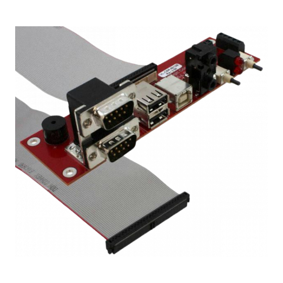
Physical Details – VL-CBR-5012 ONNECTOR OCATIONS COM3 Paddle Board Adapter Speaker COM4 COM1 (Top) USB0 (Top) USB2 Audio Power PLED Reset COM2 (Bottom) USB1 (Bottom) In (Top) (Top) Out (Bottom) Power (Bottom) Figure 9. VL-CBR-5012 Connector Locations VL-CBR-5012 C ONNECTOR UNCTIONS Table 2: VL-CBR-5012 Connector Functions and Interface Cables Connector... -
Page 24: Jumper Blocks
Physical Details Jumper Blocks UMPERS HIPPED ONFIGURATION Figure 10. Jumper Block Locations VL-EPM-24 Reference Manual... -
Page 25: Jumper Summary
Physical Details UMPER UMMARY Table 3: Jumper Summary Jumper Block Description Shipped Page V1[1-2] COM1 Rx End-point Termination (Rev. 1.01 In – 120 Ohm termination active and later) Out – No termination Places terminating resistor across COM1 RS-485 TXRX+/TXRX- or (Rev. -
Page 26: System Features
The +3.3 V , +12 V and -12 V inputs are necessary for expansion modules that require these voltages. Figure 11 shows the VersaLogic standard pin numbering for this type of 10-pin power connector and the corresponding mating connector. VL-EPM-24 Reference Manual... -
Page 27: Power Requirements
System Features Some manufacturers include a pin-1 indicator that corresponds to pin-10 of the power connector pinout VL-CBR-1008 1 3 5 Figure 11. J9 and VL-CBR-1008 Pin Numbering OWER EQUIREMENTS The VL-EPM-24 requires only +5V (±5%) for proper operation. The voltage required for the RS-232 ports is generated with an on-board DC/DC converter. -
Page 28: Cpu
The Intel Atom Z5xx processors support only JEDEC SO-DIMM raw card types A or C. They currently do not support most 16-chip memory modules, raw card type E. Use only the VersaLogic VL-MM8 family of approved memory modules. As Intel issues microcode updates, additional memory vendors may be qualified. -
Page 29: Default Cmos Ram Setup Values
System Features CMOS RAM S EFAULT ETUP ALUES After CMOS RAM is cleared, the system will load default CMOS RAM parameters the next time the board is powered on. The default CMOS RAM setup values will be used in order to boot the system whenever the main CMOS RAM values are blank, or when the system battery is dead or has been removed from the board. -
Page 30: Entering Standby Mode
System Features NTERING TANDBY Standby mode can be entered through the OS (by configuring the standby settings in Power Options Properties) or programmatically, through a function call or the execution of a shutdown utility. SetSystemPowerState Function The “Power Management Reference” in the MSDN Library contains complete information on the API available for power control under Windows. -
Page 31: Watchdog Timer
System Features Watchdog Timer A watchdog timer can be implemented using the VL-EPM-24 WDT register and the SMSC SCH3114 Super I/O chip. The BIOS initializes the SCH3114 WDT registers during post. See the SCH311X Datasheet for detailed Super I/O chip information. 1. -
Page 32: Interfaces And Connectors
Interfaces and Connectors Ethernet Interface (J5) The VL-EPM-24 features an on-board Intel 82574IT gigabit Ethernet controller, which provides a standard IEEE 802.3 Ethernet interface for 1000Base-T, 100Base-T, 100Base-TX, and 10Base- T applications. The 82574IT consumes one PCIe lane operating at 2.5 Mbps with sufficient bandwidth to support a 1000 Mbps transfer rate. -
Page 33: Video Interface (J11)
Interfaces and Connectors Video Interface (J11) An on-board video controller integrated into the chipset provides high-performance LVDS video output for the VL-EPM-24. The VL-EPM-24 can also be operated with a VGA monitor through an adapter. ONFIGURATION The VL-EPM-24 uses a shared-memory architecture. This allows the video controller to use 256 MB of system DRAM for video RAM. -
Page 34: Compatible Lvds Panel Displays
Interfaces and Connectors LVDS P OMPATIBLE ANEL ISPLAYS The following list of flat panel displays is reported to work properly with the integrated graphics video controller chip used on the VL-EPM-24. Table 7: Compatible Flat Panel Displays Model Panel Panel Manufacture Number Size... -
Page 35: Console Redirection
Interfaces and Connectors ONSOLE EDIRECTION The VL-EPM-24 can be operated without using the on-board video output by redirecting the console to a serial communications port. CMOS Setup and some operating systems such as DOS can use this console for user interaction. Console redirection settings are configured on the Features tab of CMOS Setup. -
Page 36: Ide / Pata Interface (J3)
VersaLogic offers a number of Disk on Module (DOM) flash storage devices, in capacities from 1 to 8 GB, that attach to the IDE connector. The VL-F20 series of DOMs have a 44-pin 2 mm connector and are secured to the board with one M2.5 x 6 mm nylon pan head Philips screw. -
Page 37: Loading Software Onto A Disk On Module Device
ISK ON ODULE EVICE VersaLogic recommends that you load operating systems or other software onto a DOM device via a USB drive or through the Ethernet interface. Warning! If you attach a DOM to an IDE cable, be careful to preserve proper signal-to-signal integrity. -
Page 38: Main I/O Connector (J4)
Interfaces and Connectors Main I/O Connector (J4) The J4 50-pin main I/O connector incorporates the serial (COM) ports, USB ports, PLED, speaker, and the reset button. Table 9 shows the function of each pin and the pinout assignments to connectors on the VL-CBR-5012 breakout board. The +5V power provided to pins 49 and 50 of J4 is protected by a 1 amp fuse. -
Page 39: Serial Ports
Interfaces and Connectors Serial Ports The VL-EPM-24 features four on-board 16550-based serial communication channels (COM ports) located at standard PC I/O addresses. Connector J4 provides interfaces to the serial ports. All serial ports can be operated in RS-232, RS-422, or RS-485 modes. The mode is selected in CMOS Setup . -
Page 40: Serial (Com) Port Connector Pin Functions
Interfaces and Connectors (COM) P ERIAL ONNECTOR UNCTIONS The following tables show the pinouts for the serial port connectors on the VL-CBR-5012 breakout board. See Table 9 for the serial port pinouts on connector J4 of the motherboard. Note: The pins indicated as shorted in the following table are shorted only on the VL- CBR-5012 breakout board, not connector J4 of the motherboard. -
Page 41: Usb Interface
Interfaces and Connectors USB Interface The USB interface on the VL-EPM-24 is UHCI (Universal Host Controller Interface) and EHCI (Enhance Host Controller Interface) compatible, which provides a common industry software/hardware interface. Connector J4 includes interfaces for three USB ports (USB0-2). The VL-CBR-5012 breakout board connects to J4 and provides two Type A USB connectors and one Type B USB connector. -
Page 42: Usb Client Mode
When operated in Client mode, USB2 can operate as a USB networking or a USB mass storage device when connected to an external host computer. In other words, the Tiger can appear as a USB mass storage device to a standard Windows XP workstation. When operated in Host mode, external USB power must be provided for any device attached via the USB Type B (J7) connector on the VL-CBR-5012. -
Page 43: Audio
Interfaces and Connectors Audio The audio interface on the VL-EPM-24 is implemented using an Integrated Device Technology, Inc. 92HD87B1X5 Audio Codec. This interface is Intel High Definition Audio compatible. Drivers are available for most Windows-based and Linux operating systems. To obtain the most current versions, consult the VL-EPM-24 product support page. -
Page 44: Pc/104 I/O Cycle Support
Interfaces and Connectors PC/104 I/O C YCLE UPPORT I/O cycles are 8-bit by default. 16-bit cycles are supported with the following caveats: All PC/104 modules are 16-bit capable and must assert IOCS16# 16-bit cycles are enabled in CMOS Setup ... -
Page 45: Spx Expansion Bus (J6)
XPANSION ODULES VersaLogic offers a number of SPX modules that provide a variety of standard functions, such as analog input, digital I/O, CANbus interface, and others. These are small boards (1.2” x 3.78”) that can mount on the system stack using standoffs (VL-HDW-105) or up to two feet away from info@VersaLogic.com... -
Page 46: Spi Registers
Interfaces and Connectors SPI R EGISTERS A set of control and data registers are available for SPI transactions. The following tables describe the SPI control registers (SPICONTROL and SPISTATUS) and data registers (SPIDATA3-0). SPICONTROL (READ/WRITE) 1D8h CPOL CPHA SPILEN1 SPILEN0 MAN_SS Table 15: SPI Control Register Bit Assignments Mnemonic... - Page 47 Interfaces and Connectors SPISTATUS (READ/WRITE) 1D9h IRQSEL1 IRQSEL0 SPICLK1 SPICLK0 HW_IRQ_EN LSBIT_1ST HW_INT BUSY Table 16: SPI Control Register Assignments Mnemonic Description IRQ Select – These bits select which IRQ will be asserted when a hardware D7-D6 IRQSEL interrupt from a connected SPI device occurs. The HW_IRQ_EN bit must be set to enable SPI IRQ functionality.
- Page 48 Interfaces and Connectors SPIDATA0 (READ/WRITE) 1DAh MSbit LSbit SPIDATA1 (READ/WRITE) 1DBh MSbit LSbit SPIDATA2 (READ/WRITE) 1DCh MSbit LSbit SPIDATA3 (READ/WRITE) 1DDh MSbit LSbit SPIDATA3 contains the most significant byte (MSB) of the SPI data word. A write to this register will initiate the SPI clock and, if the MAN_SS bit = 0, will also assert a slave select to begin an SPI bus transaction.
-
Page 49: System Resources And Maps
System Resources and Maps Memory Map The lower 1 MB memory map of the VL-EPM-24 is arranged as shown in the following table. Various blocks of memory space between A0000h and FFFFFh are shadowed. Table 17: Memory Map Start Address Address Comment F0000h... -
Page 50: Interrupt Configuration
Interfaces and Connectors Interrupt Configuration Table 19: Interrupt Configuration = default setting = allowed setting Source Timer 0 Keyboard Slave PIC COM1 COM2 ... -
Page 51: Special Registers
Special Registers PLED and Product ID Register PLEDPC (Read/Write) 1D0h PLED Table 20: PLED and Product Code Register Bit Assignments Mnemonic Description Light Emitting Diode — Controls the programmable LED on connector J4. PLED 0 = Turns LED off 1 = Turns LED on Product Code —... -
Page 52: Revision And Type Register
Special Registers Revision and Type Register REVTYP (Read Only) 1D1h TEMP CUSTOM BETA This register is used to indicate the revision level of the VL-EPM-24 PLD firmware. Table 21: Revision and Type Register Bit Assignments Mnemonic Description PLD Revision Code — These bits are hard-coded and represent the CPLD D7-D3 revision. -
Page 53: Gpi Jumper Register
Special Registers GPI Jumper Register GPI (Read Only) 1D2h Reserved Reserved Reserved Reserved Reserved Reserved GPI1_JMP GPI2_JMP Table 22: GPI Jumper Register Bit Assignments Mnemonic Description D7-D2 Reserved These bits have no function. General Purpose Input 1 Jumper — Indicates the status of jumper V3[1-2]. GPI1_JMP 0 = Jumper out 1 = Jumper in... -
Page 54: Watchdog Timer Register
Special Registers Watchdog Timer Register This register controls the behavior of the System Management Controller if the Super I/O watchdog timer interrupt pins have been asserted. The actual conditions and setup of the watchdog timer are configured in the SMSC SCH3114 and Intel SCH ACPI register interface. WDTHWM (Read Only) 1D3h WDT_ST Reserved... -
Page 55: Pc/104 I/O Block Enable Registers
Special Registers PC/104 I/O Block Enable Registers These registers are used to configure the LPC-to-PC/104 bus bridge. I/O port addresses are divided into blocks. Each block has its own enable bit that allows the I/O ports within the block to be forwarded from the LPC bus to the PC/104 bus and vice versa. These registers are set in CMOS Setup, but are accessible to user software for runtime configuration as well. - Page 56 Special Registers PC104_BLK_EN1 (Read/Write) 1D5h Reserved Reserved Reserved Reserved IOBLK_EN11 IOBLK_EN10 IOBLK_EN9 IOBLK_EN8 Table 25: PC/104 I/O Block Enable Register 1 Bit Assignments Mnemonic Description D7-D4 These bits have no function. Reserved IOBLK_EN11 PC/104 I/O port range 0x400 - 0xAFF enable 0 = disabled on PC/104 bus 1 = enabled on PC/104 bus IOBLK_EN10...
-
Page 57: Pc/104 Interrupt Request Enable Registers
Special Registers PC/104 Interrupt Request Enable Registers These registers are used to configure PC/104 bus IRQs. Legacy IRQs on the Serial IRQ (LPC) bus each have an enable bit that allows the IRQ to be forwarded from the PC/104 bus to the Serial IRQ (LPC) bus. - Page 58 Special Registers PC104_IRQ_EN1 (Read/Write) 1DFh 16BIT_EN MEM_EN3 MEM_EN2 MEM_EN1 MEM_EN0 Reserved IRQ15_EN IRQ12_EN Table 27: PC/104 Interrupt Request Register 1 Bit Assignments Mnemonic Description PC/104 16 bit I/O cycle enable – This bit controls 16bit I/O cycles on the PC/104 16BIT_EN bus.
-
Page 59: Appendix A - References
Appendix A – References Processor + Chipset Intel Atom Datasheet Intel Atom Z5xx (Menlow XL) Ethernet Controller Intel 82574L Datasheet Intel 82574L Ethernet Controller PC/104 PC/104 Specification PC/104-Plus PC/104-Plus Specification VL-EPM-24 Reference Manual...
Need help?
Do you have a question about the Tiger and is the answer not in the manual?
Questions and answers