Advertisement
Quick Links
Advertisement

Related Manuals for Assa Abloy Sargent SE LP10


Summary of Contents for Assa Abloy Sargent SE LP10
- Page 1 SE LP10 Mortise Lock Installation Instructions A8113H 05/20 Copyright © 2020, Sargent Manufacturing Company, an ASSA ABLOY Group company. All rights reserved. Reproduction in whole or in part without the express written permission of Sargent Manufacturing Company is prohibited.
-
Page 2: Table Of Contents
SE LP10 Mortise Lock Table of Contents Regulatory Compliance ............3 Warning ..................3 General Description ..............5 Specifications/Features ............5 Parts Breakdown ..............7 Wiring Diagrams ..............9 Installation Instructions ............12 Operational Check ..............21 A8113H • 800-810-WIRE (9473) • www.sargentlock.com... -
Page 3: Regulatory Compliance
SE LP10 Mortise Lock Regulatory Compliance Changes or modifications to this unit not expressly approved by the party responsible for compliance could void the user’s authority to operate the equipment. This equipment has been tested and found to comply with the limits for a Class B digital device, pursuant to Part 15 of the FCC Rules. These limits are designed to provide reasonable protection against harmful interference in a residential installation. -
Page 4: General Description
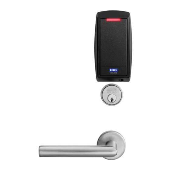
SE LP10 Mortise Lock General Description The SARGENT SE LP10 brings flexibility to our Integrated Wired access control solutions. Featuring multiCLASS SE Technology from HID Global , the SE LP10 is ideal for mixed ® ® credential environments and enables easy migration to higher security credentials and mobile access. - Page 5 SE LP10 Mortise Lock Specifications / Features (Continued) • UL Listed* - UL 294 Indoor Use • UL 294 Access Control Ratings: • CUL Listed - S319: Class 1 Destructive Attack Level 1 • ANSI/BHMA A156.25 Listed Line Security Level 1 Grade 1 Compliant Endurance Level 4...
-
Page 6: Parts Breakdown
SE LP10 Mortise Lock Parts Breakdown Tools Required: • Phillips Screw Driver (Standard size) • Slotted Screw Driver (Standard size) • 1/8" Allen Wrench A8113H • 800-810-WIRE (9473) • www.sargentlock.com... - Page 7 SE LP10 Mortise Lock Parts Breakdown (Continued) ITEM PART # Description Req. 52-4922 BIPS-03 Reader and Harness Assembly - Bluetooth (Standard Indicator Configuration) 52-4528 FIPS-03 Reader & Harness Assembly - 200 bit Wiegand output 52-4567 FIPS-04 Reader & Harness Assembly - 75 bit Wiegand output 52-4524 IPS-03 Reader &...
-
Page 8: Wiring Diagrams
SE LP10 Mortise Lock Wiring Diagrams Product 8 PIN CONNECTOR 4 PIN CONNECTOR 1-Black 2-Red 3-White 4-Green 5-Orange 6-Blue 7-Brown 8-Yellow 1-Violet 2-Gray 3-Pink 4-Tan ACCESS CONTROL DEVICES: SE LP10 Mortise, ElectroLynx wire Color / Function assignments 12VDC WIEGAND WIEGAND EGND TAMPER 12/24 VDC... - Page 9 SE LP10 Mortise Lock Typical (UL294-Compliant) SE LP10 Mortise Application Diagram #1 Tamper will trigger when reader is removed from door and tamper wiring is connected at the panel. 12/24VDC System Average Peak Average Peak Reader 100mA 220mA Actuator 15mA 500mA 15mA 500mA...
- Page 10 SE LP10 Mortise Lock Alternate Indicator Application Diagram #2 (12/24VDC System) Connect GREEN_LED input to switch controlled by panel. Shorting GREEN_LED to READER_NEG (Black) with panel switch will override reader LED to keep it green. Average Peak Average Peak Reader 100mA 220mA Actuator...
-
Page 11: Installation Instructions
SE LP10 Mortise Lock Installation Instructions 1 Door Preparation A. Verify Hand and Bevel of Door Stand on outside of locked door when determining door hand. Left Hand Left Hand Right Hand Right Hand Hinges Left. Reverse Bevel Hinges Right. Reverse Bevel Open Inward. - Page 12 SE LP10 Mortise Lock 2 How to Change Hand of Lock body A. Reverse Lock Hand Red surface of locking piece must face the outside/locked side of door. To rotate locking Right Hand piece (Fig. 2A): Lock Shown A. Position lock body with red surface of locking piece visible.
- Page 13 SE LP10 Mortise Lock 4 Install Lock Body A. First insert lock body wire harness into the mortised area and out of the inside cylinder hole (Fig. 4A). B. Insert mortise lock body into mortise door preparation, continuing to feed wires from lock body through the non-cylinder (inside) hole of the door preparation.
- Page 14 SE LP10 Mortise Lock 5 Install Reader Backplate and (Optional*) Fire Shield or Gasket A. For fire-rated doors only, install reader backplate and fire shield to door using two (2) #8-18 x 5/8” Phillips flat head self-drilling screws (Fig. 5A). B.
- Page 15 SE LP10 Mortise Lock 7 Installation of SE LP10 Reader and Trim Bezel Observe precautions for handling electrostatic sensitive devices. If the SE LP10 reader is installed with a module (Fig. 7A), make sure that the reader is powered down when inserting/removing the module; i.e., do not “hot-plug”...
- Page 16 SE LP10 Mortise Lock 8 Wire Connections Do not offset connectors and ensure that they are completely seated. A. Connect 6-pin connector from lock body to 6-pin connector on reader harness (Fig. 8A). B. Connect 2-pin connector from lock body to 2-pin connector on reader harness (Fig. 8A). Fig.
- Page 17 SE LP10 Mortise Lock 9 (Optional) Fire Plate Installation *(2) Phillips A. Install the fire plate to the mounting plate (Fig 9), being careful not to #8 x 1/2” trap or pinch wires between fire plate and mounting plate. Fasten plate flat head with two (2) #8 x 1 1/4”...
- Page 18 SE LP10 Mortise Lock 11 Inside Outside Lever and Inside Adapter Plate Assembly A. With outside lever horizontal, insert mounting posts through outside of door and lock body. Make certain the lever spindle is properly engaged inside the lock body (Fig 11A). B.
- Page 19 SE LP10 Mortise Lock 13 Install Inside Rose and Inside Lever Assembly A. Rotate the inside rose first counter clockwise to seat the threads then clockwise to securely tighten. Inside of Door B. Slide lever handle onto spindle until fully seated.
-
Page 20: Operational Check
E. Close door: Ensure latch and deadbolt fully extend and do not bind. Wiegand Test Unit Feature The ASSA ABLOY Wiegand Test Unit verifies your installation in 12 or 24VDC solenoid lock voltage adjustable the field*. The test unit checks for proper wiring, card reader data... - Page 21 SE LP10 Mortise Lock Operational Check (Continued) Note: Once electrical wiring has been successfully completed according to proper application, perform the following steps: A. Ensure lock is interfaced with Wiegand Test Unit to verify installation and wiring up to (frame side) point of hinge. B.
- Page 22 SE LP10 Mortise Lock Notes A8113H • 800-810-WIRE (9473) • www.sargentlock.com...
- Page 23 SE LP10 Mortise Lock A8113H • 800-810-WIRE (9473) • www.sargentlock.com...
- Page 24 The company’s customer base includes commercial construction, institutional, and industrial markets. Copyright 2020, Sargent Manufacturing Company, an ASSA ABLOY Group company. All rights reserved. © Reproduction in whole or in part without the express written permission of Sargent Manufacturing Company is prohibited.
Need help?
Do you have a question about the Sargent SE LP10 and is the answer not in the manual?
Questions and answers