Table of Contents
Advertisement
Quick Links
Advertisement
Table of Contents

Related Manuals for Agilent Technologies N6751A


Summary of Contents for Agilent Technologies N6751A
- Page 1 Agilent Technologies Modular Power System Series N6700 User’s Guide...
- Page 2 Legal Notices Certification Technologies Licenses © Agilent Technologies, Inc. 2003 - 2005 Agilent Technologies certifies that this The hardware and or software described product met its published specifications in this document are furnished under a No part of this document may be at time of shipment from the factory.
- Page 3 Safety Notices Do Not Operate in an Explosive Safety Symbols Atmosphere Direct current The following general safety precautions Do not operate the instrument in the must be observed during all phases of Alternating current presence of flammable gases or fumes. operation of this instrument.
- Page 4 Agilent Series 662xA DC power supplies that are supported by the Agilent N6700 Modular Power System. NOTE You can contact Agilent Technologies at one of the following telephone numbers for warranty, service, or technical support information. In the United States: (800) 829-4444...
-
Page 5: Table Of Contents
Contents 1 Quick Reference The Agilent N6700 Modular Power System – At a Glance......8 The Front Panel - At a Glance................. 10 The Rear Panel – At a Glance................. 10 Front Panel Display – At a Glance ..............11 Front Panel Keys –... - Page 6 6 Language Dictionary SCPI Command Summary................76 Calibration Subsystem..................80 Display Subsystem.................... 82 Measurement Subsystem................83 Output Subsystem..................... 86 Source Subsystem .................... 89 Status Subsystem ..................... 96 System Commands ..................103 Trigger Subsystem ..................107 7 Programming Examples Output Programming Example ..............110 List Programming Example................112 Digitizer Programming Example..............114 Appendix A Specifications...
-
Page 7: Quick Reference
Quick Reference The Agilent N6700 Modular Power System – At a Glance......8 The Front Panel - At a Glance................. 10 The Rear Panel – At a Glance................. 10 Front Panel Display – At a Glance ..............11 Front Panel Keys – At a Glance.............. -
Page 8: The Agilent N6700 Modular Power System - At A Glance
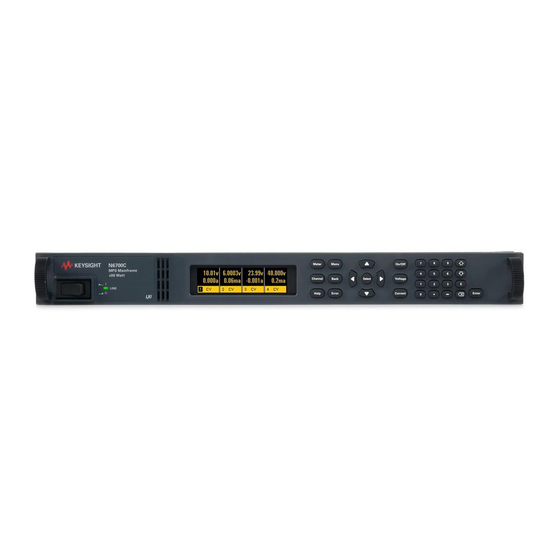
1 Quick Reference The Agilent N6700 Modular Power System – At a Glance The Agilent N6700 Modular Power System is a configurable, 1U (rack unit) high platform that lets you mix and match power modules to create a power system optimized for your test system requirements. Up to four power modules can be installed in each Agilent N6700A/B MPS mainframe. - Page 9 This information can be displayed on the front panel. Model Differences Feature DC Power Modules (A+B) Autoranging Modules Precision Modules N6731 - N6741 - N6751A N6752A N6761A N6762A N6736 N6746 Output power rating 50 W 100 W...
-
Page 10: The Front Panel - At A Glance
1 Quick Reference The Front Panel - At a Glance Display Navigation keys Output keys Turns off after 1 hour of Move the cursor to a menu item. Turn the outputs on or off. inactivity. Press any key to Select the highlighted menu item. Enter voltage or current. -
Page 11: Front Panel Display - At A Glance
Quick Reference 1 Front Panel Display – At a Glance Single-channel View Voltage measurement Current measurement Press the Meter key to toggle between views Operating mode (CV = Voltage and Current Remote interface status constant voltage mode) settings (ALL, SRQ, ERR, IO) Multiple-channel View Voltage and Current measurements Press the Meter key to toggle between... -
Page 12: Front Panel Keys - At A Glance
1 Quick Reference Front Panel Keys – At a Glance System Keys Meter returns the display to metering mode. Meter Menu Menu accesses the command menu. Channel selects or highlights a channel to control. Back Channel Back backs out of a menu without activating any changes. Help accesses information about the displayed menu control. -
Page 13: Front Panel Menu Reference
Quick Reference 1 Front Panel Menu Reference Menu commands that appear grayed-out on the display are either not available NOTE for the power module that is being programmed, or are password protected. Refer to appendix E for information about the front panel menu commands for firmware revisions prior to B.00.00 Menu Command Control Description... - Page 14 1 Quick Reference Menu Command Control Description System GPIB Selects the GPIB address. DigPort Pin 1 Function Specifies the pin function: DigIO, TrigIn, TrigOut, DigIn, FaultOut. Polarity Specifies the pin polarity. Pin 2 Function Specifies the pin function: DigIO, TrigIn, TrigOut, DigIn. Polarity Specifies the pin polarity.
-
Page 15: Installation
Installation General Information..................16 Inspecting the Unit ................... 17 Installing the Unit....................17 Connecting the Line Cord ................19 Connecting the Outputs................... 20 Remote Sense Connections ................24 Parallel Connections..................25 Series Connections................... 26 This chapter describes how to install your power system. It discusses installation, rack mounting, and line cord connections. -
Page 16: General Information
Description High-speed Test Extensions. Includes digitized output measurements and output list capability. Available for Agilent Models N6751A/N6752A. Included with Agilent Models N6761A/N6762A. Output relays. Includes 2 - DPDT galvanic-disconnect relays. Disconnects both output and sense terminals. Available for all Agilent Models. -
Page 17: Inspecting The Unit
Installation 2 Inspecting the Unit When you receive your power system, inspect it for any obvious damage that may have occurred during shipment. If there is damage, notify the shipping carrier and nearest Agilent Sales and Support Office immediately. Refer to Appendix D for more information. Until you have checked out the power system, save the shipping carton and packing materials in case the unit has to be returned. - Page 18 2 Installation The Agilent N6700 MPS can be mounted in a 19-inch EIA rack cabinet. It is designed to fit in one rack unit (1U) of space. Install the rack mount kit as shown in the following figure. Step 1. Install eight clip-nuts on the rack frame (2 in each corner) where your instrument will be located Step 2.
-
Page 19: Connecting The Line Cord
Installation 2 Bench Installation Do not block the air intake and exhaust at the sides, or the exhaust at the rear of the unit. Refer to the outline diagram in Appendix A. Minimum clearances for bench operation are 2 inches (51 mm) along the sides and back. -
Page 20: Connecting The Outputs
2 Installation 400 Hz Operating Considerations Power Factor At 400 Hz operation, the unit’s power factor is affected as follows: Under full load at 400 Hz, power factor drops from 0.99 (@120 VAC) to as low as 0.76 (@ 265 VAC) Power factor degrades further under no load conditions. - Page 21 Installation 2 Wire Size FIRE HAZARD Select a wire size large enough to carry short-circuit current WARNING without overheating. To satisfy safety requirements, load wires must be heavy enough not to overheat while carrying the short-circuit output current of the unit (refer to the following chart). Along with conductor temperature, you must also consider voltage drop when selecting wire sizes.
- Page 22 2 Installation Multiple Loads If you are using local sensing and are connecting multiple loads to one output, connect each load to the output terminals using separate connecting wires (see the figure below). This minimizes mutual coupling effects and takes full advantage of the power system's low output impedance.
- Page 23 Installation 2 Remote Voltage Sensing Because of the unavoidable voltage drop developed in the load leads, the terminal block strapping patterns discussed thus far do not provide the best possible voltage regulation at the load. The remote sensing connections shown in the figure below improve the voltage regulation at the load by monitoring the voltage there instead of at the output terminals.
-
Page 24: Remote Sense Connections
2 Installation Remote Sense Connections Remember to turn off the power system before making or changing any connections on the rear panel terminal blocks. Connect the unit for remote sensing by first disconnecting the straps between sense and load terminals. Make your connections as shown in the previous figure. -
Page 25: Parallel Connections
Installation 2 Parallel Connections Only connect outputs that have identical voltage and current ratings in parallel. CAUTION Connecting outputs in parallel provides a greater current capability than can be obtained from a single output. The following figures show how to connect two outputs in parallel. The figure on the left illustrates local sensing. -
Page 26: Series Connections
2 Installation Effect on Specifications Specifications for outputs operating in parallel can be obtained from the specifications for single outputs. Most specifications are expressed as a constant or as a percentage (or ppm) plus a constant. For parallel operation, the percentage portion remains unchanged while constant portions or any constants are changed as indicated below. - Page 27 Installation 2 OUTPUT 2 OUTPUT 1 OUTPUT 2 OUTPUT 1 SENSE SENSE JUMPER JUMPERS INSTALLED INSTALLED TWIST LEADS TWIST LEADS LOAD LOAD WITH LOCAL SENSING WITH REMOTE SENSING Setting the Outputs Outputs connected together in series cannot be grouped. To program outputs connected in series, first program the current limit of each output to the total desired current limit point.
-
Page 29: Getting Started
Detailed information on configuring the remote interfaces is included in the NOTE Agilent Technologies USB/LAN/GPIB Interfaces Connectivity Guide, which is available on the Automation-Ready CD-ROM included with this product Series N6700 User’s Guide... -
Page 30: Turning The Unit On
3 Getting Started Turning the Unit On After you have connected the line cord, turn the unit on with the front panel power switch. The front panel display will light up after a few seconds. A power-on self-test occurs automatically when you turn the unit on. This test assures you that the instrument is operational. -
Page 31: Entering A Current Limit Setting
Getting Started 3 Entering a Current Limit Setting Method 1 – Use the Navigation and Arrow Keys Navigation Keys Use the left and right navigation keys to navigate to the setting that you wish to change. In the display below, channel 1’s current setting is selected. Enter a value using the numeric keypad. -
Page 32: Using The Front Panel Menu
3 Getting Started Using the Front Panel Menu The front panel command menu lets you access most of the power system’s functions. The actual function controls are located at the lowest menu level. Briefly: Press the Menu key to access the command menu. Press the navigation keys to move across the menu commands. - Page 33 Getting Started 3 The command menu is now at the function control level. This is the lowest level in this path. Use the navigation keys to highlight the OVP Level control as shown below. Enter the desired over-voltage level using the numeric keypad. Then press Enter.
-
Page 34: Connecting To The Interfaces
3 Getting Started Connecting to the Interfaces Electrostatic discharges greater than 1 kV near the interface connectors may CAUTION cause the unit to reset and require operator intervention. The Agilent N6700 MPS supports GPIB, LAN, and USB interfaces. All three interfaces are live at power-on. The IO annunciator on the front panel comes on whenever there is activity on the remote interfaces. - Page 35 Getting Started 3 USB Interface For detailed information about USB interface connections, refer to the Agilent NOTE Technologies USB/LAN/GPIB Interfaces Connectivity Guide, located on the Automation-Ready CD-ROM that is shipped with your product. The following steps will help you quickly get started connecting your USB-enabled instrument to the Universal Serial Bus (USB).
- Page 36 If this does not work, refer to the chapter on “Troubleshooting Guidelines” in NOTE the Agilent Technologies USB/LAN/GPIB Interfaces Connectivity Guide. You can now use Interactive IO within the Connection Expert to communicate with your instrument, or you can program your instrument using the various programming environments.
- Page 37 If the instrument cannot be found, you can add the instrument using the instrument’s hostname or IP address. If this does not work, refer to the chapter on “Troubleshooting Guidelines” in the NOTE Agilent Technologies USB/LAN/GPIB Interfaces Connectivity Guide. Series N6700 User’s Guide...
- Page 38 3 Getting Started You can now use Interactive IO within the Connection Expert to communicate with your instrument, or you can program your instrument using the various programming environments. You can also use the Web browser on your computer to communicate with the instrument as described under “Using the Web Server”...
- Page 39 Getting Started 3 Enable AutoIP This parameter allows automatic IP addressing to be enabled or disabled. AutoIP automatically assigns addresses on networks that do not have a DHCP server. If AutoIP is enabled (On), an IP address, Subnet Mask and Default Gateway will automatically be assigned to the instrument.
- Page 40 3 Getting Started Use Dynamic DNS Registers the hostname using the Dynamic DNS naming naming service system. Use NetBIOS Registers the hostname using the RFC NetBIOS naming naming service protocol. Select Domain if your DNS server requires an instrument to register not only the hostname, but also the domain name.
- Page 41 Getting Started 3 Communicating over the LAN The Agilent IO Libraries Suite along with instrument drivers for specific programming environments can be used to communicate with your power system. You can also communicate with your power system using its built-in Web server, the Telnet utility, or sockets. These latter methods are a convenient way to communicate with the power system without using I/O libraries or drivers.
- Page 42 3 Getting Started Click on the Browser Web Control button in the navigation bar on the left to begin controlling your instrument. For additional help about any of the pages, click on the Help with this Page button. Using Telnet In an MS-DOS Command Prompt box type: telnet hostname 5024 where hostname is the N6700 hostname or IP address, and 5024 is the instrument’s telnet port.
- Page 43 Getting Started 3 Securing the Interfaces Enable/Disable the USB, LAN, and Web Server The USB interface, LAN interface, and the Web server are enabled when shipped. To enable or disable the USB interface from the front panel, press the Menu key and select System\Admin\USB. Enable USB Check this box to enable the USB.
- Page 44 3 Getting Started Factory-shipped non-volatile LAN settings DHCP Enabled Hostname A-N6700B-xxxxx AutoIP Enabled Use DNS naming service Enabled IP Address 169.254.67.0 Use NetBIOS naming service Enabled Subnet Mask 255.255.0.0 Domain Name Blank Default Gateway 0.0.0.0 TCP keepalive Enabled Obtain DNS server from DHCP Enabled TCP keepalive seconds 1800...
-
Page 45: Operating The Power System
Operating the Power System Programming the Output ................. 46 Synchronizing Output Steps................49 Making Measurements..................52 System Related Operations................53 Programming High-Speed Test Extensions ..........57 This chapter contains examples on how to operate your power system from the front panel and over the remote interface using SCPI commands. -
Page 46: Programming The Output
4 Operating the Power System Programming the Output Select an Output Channel Front Panel: SCPI Command: Press the Channel key to select an Enter the selected channel(s) in the output channel. command’s parameter list. (@1,2) Set the Output Voltage Front Panel: SCPI Command: Press the Voltage key. - Page 47 Operating the Power System 4 For models with multiple ranges, you can select a lower range if you need better output resolution. Front Panel: SCPI Command: Press the Current key. To select the lower range, program a value that falls within the range: Select Low range and press Select.
- Page 48 4 Operating the Power System However, when outputs of different module types are sequenced, there may be an additional offset of a few milliseconds from one output to another. This offset is the same for each module type and is repeatable.
-
Page 49: Synchronizing Output Steps
Operating the Power System 4 Synchronizing Output Steps The transient system lets you step the output voltage and current up or down in response to triggered events. To generate a triggered output step you must: 1. Enable the output to respond to trigger commands. 2. - Page 50 4 Operating the Power System Select the Transient Trigger Source An immediate trigger command either from the front panel or over the bus will NOTE generate an immediate trigger regardless of the trigger source. Unless you are using the front panel menu or a TRIG:TRAN command to trigger the output, select a trigger source from the following: Selects GPIB device trigger, *TRG, or <GET>...
- Page 51 Operating the Power System 4 Trigger the Output The trigger system is waiting for a trigger signal in the initiated state. You can immediately trigger the output as follows: Front Panel: SCPI Command: Select Transient\Control. To generate an immediate trigger on channel 1: Select Trigger to generate an immediate trigger signal regardless...
-
Page 52: Making Measurements
4 Operating the Power System Making Measurements Each output channel has its own measurement capability. The output voltage and current is measured by acquiring a number of samples at the selected time interval, applying a window function to the samples, and averaging the samples. The power-on and *RST time interval and number of samples settings yield a measurement time of 21 milliseconds per reading (1024 data points at 20.48 µs intervals). -
Page 53: System Related Operations
Operating the Power System 4 System Related Operations Self-Test A power-on self-test occurs automatically when you turn on the power system. This test assures you that the instrument is operational. If the self-test is successful, the power system will continue to operate normally. - Page 54 4 Operating the Power System Output Groups The ability to group outputs is only available on Agilent N6700 MPS mainframes NOTE with firmware revision B.00.00 and up. Output channels can be configured or “grouped” to create a single output with higher current and power capability. Almost all instrument functionality is supported by grouped channels, including voltage and current programming, measurements, status, step transients, and list transients.
- Page 55 Operating the Power System 4 Front Panel Keys Lockout The ability to lock the front panel from the front panel is only available on NOTE Agilent N6700 MPS mainframes with firmware revision B.00.00 and up. You can lock the front panel keys to prevent unwanted control of the instrument from the front panel.
- Page 56 4 Operating the Power System Front Panel Display Screen Saver The power system has a front panel screen saver that significantly increases the life of the LCD display by turning it off during periods of inactivity. As shipped from the factory, the screen saver comes on one hour after activity on the front panel or interface has ceased.
-
Page 57: Programming High-Speed Test Extensions
Operating the Power System 4 Programming High-Speed Test Extensions The High-Speed Test Extensions described in this section are not available on NOTE all models (Refer to Chapter 1, “Model Differences”). The List Function Either output voltage or output current, or both together, may be list- controlled. - Page 58 4 Operating the Power System Program an Output Pulse or Pulse Train The following procedure shows how to generate an output pulse train using the List function. Trigger Pulse width List Count = 1+additional pulses time Step 1. Set the voltage or current function for which you want to generate a pulse to List mode.
- Page 59 Operating the Power System 4 Step 5. To generate a pulse train, you can simply repeat the pulse as needed. For example, to program a pulse train of 50 pulses, use: Front Panel: SCPI Command: Select Transient\List\Repeat. To program output 1, use Enter the number of list repetitions LIST:COUN 50, (@1) (50) and Press Select.
- Page 60 4 Operating the Power System Program an Arbitrary List The following procedure shows how to generate the list of voltage changes as illustrated in the following figure. Trigger List Count = 1 List Count = 2 Step 1. Set the function, voltage or current, for which you want to generate a list to List mode.
- Page 61 Operating the Power System 4 Front Panel: SCPI Command: Select Transient\List\Pace. LIST:STEP AUTO, (@1) Select Dwell-paced. Press Select. In a trigger-paced list, the list advances one step for each trigger received. To enable trigger-paced lists, select Trigger-paced on the front panel menu. (Set the LIST:STEP command to ONCE.) The dwell time associated with each step determines the minimum time that the output remains at the step.
- Page 62 4 Operating the Power System The Digitizer Function The digitizer function lets you access the enhanced voltage and current measurement capabilities of the power system. These include: Adjusting the measurement sample rate - to a maximum of 50 kHz. Adjusting measurement triggers to capture pre-trigger transients. Selecting a measurement window that can attenuate ac noise.
- Page 63 Operating the Power System 4 4096 DATA POINTS OFFSET = -4095 4096 DATA POINTS OFFSET = -2048 4096 DATA POINTS OFFSET = 0 OFFSET = 0 to 2 4096 DATA POINTS TIME TRIGGER To offset the beginning of the acquisition buffer relative to the acquisition trigger, use: Front Panel: SCPI Command:...
- Page 64 4 Operating the Power System To select a window function, use: Front Panel: SCPI Command: Select Measure\Window. To set the sense window to Hanning for output 1 use: Then select either Rectangular or Hanning and press Select. SENS:WIND HANN, (@1) Retrieve Measurement Array Data Array queries return all values in the voltage and current measurement buffer.
- Page 65 Operating the Power System 4 To trigger measurements on models that do not have simultaneous voltage and current measurement capability, select the measurement function as follows. Front Panel: SCPI Command: Not Available To select the measurement function: SENS:FUNC ”VOLT”,(@1:4) SENS:FUNC ”CURR”,(@1:4) If a model has simultaneous voltage and current measurements capability, then BOTH voltage and current are acquired on any triggered measurement, regardless of the setting of the...
- Page 66 4 Operating the Power System Initiate the Measurement Trigger System Next, you must initiate or enable the measurement trigger system. When the power system is turned on, the trigger system is in the idle state. In this state, the trigger system is disabled, ignoring all triggers. The INITiate commands enable the measurement system to receive triggers.
-
Page 67: Introduction To Programming
Introduction to Programming SCPI Commands....................68 SCPI Messages....................70 SCPI Conventions and Data Formats............. 72 SCPI Command Completion ................74 This chapter contains a brief introduction to the SCPI Programming language. SCPI (Standard Commands for Programmable Instruments) is a programming language for controlling instrument functions over the GPIB. -
Page 68: Scpi Commands
5 Introduction to Programming SCPI Commands SCPI has two types of commands, common and subsystem. Common commands generally control overall power system functions, such as reset, status, and synchronization. All common commands consist of a three-letter mnemonic preceded by an asterisk: *RST *IDN? *SRE 8 Subsystem commands perform specific power system functions. - Page 69 Introduction to Programming 5 defined as "OUTPut" and thus the instrument interpreted the second command as: OUTPut:PROTection:CLEar (@1) In fact, it would have been syntactically incorrect to include the "OUTP" explicitly in the second command, since the result after combining it with the header path would be: OUTPut:OUTPut:PROTection:CLEar (@1) which is incorrect.
-
Page 70: Scpi Messages
5 Introduction to Programming Coupled Commands When commands are coupled it means that the value sent by one command is affected by the settings of another command. The following commands are coupled: [SOURce:]CURRent and [SOURce:]CURRent:RANGe. [SOURce:]VOLTage and [SOURce:]VOLTage:RANGe. If a range command is sent that places an output on a range with a lower maximum setting than the present level, an error is generated. - Page 71 Introduction to Programming 5 The Message Unit The simplest SCPI command is a single message unit consisting of a command header (or keyword) followed by a message terminator such as a newline. The message unit may include a parameter after the header.
-
Page 72: Scpi Conventions And Data Formats
5 Introduction to Programming Message Unit Separator When two or more message units are combined into a compound message, separate the units with a semicolon. STATus:OPERation?(@1);QUEStionable?(@1) Root Specifier When it precedes the first header of a message unit, the colon becomes the root specifier. - Page 73 Introduction to Programming 5 Data Formats Data programmed or queried from the power system is ASCII. The data may be numerical or character string. Numeric Data Formats Symbol Response Formats <NR1> Digits with an implied decimal point assumed at the right of the least- significant digit.
-
Page 74: Scpi Command Completion
5 Introduction to Programming SCPI Command Completion SCPI commands sent to the power system are processed either sequentially or in parallel. Sequential commands finish execution before a subsequent command begins. Parallel commands allow other commands to begin executing while the parallel command is still executing. -
Page 75: Language Dictionary
Language Dictionary SCPI Command Summary................76 Calibration Subsystem..................80 Display Subsystem.................... 82 Measurement Subsystem................83 Output Subsystem..................... 86 Source Subsystem .................... 89 Status Subsystem ..................... 96 System Commands ..................103 Trigger Subsystem ..................107 This section gives the syntax and parameters for all the IEEE 488.2 SCPI commands and the Common commands used by the power system. -
Page 76: Scpi Command Summary
:CURRent [:LEVel] <NRf>, (@channel) Calibrates the output current programming :MEASure <NRf>, (@channel) Calibrates the current measurement :PEAK (@channel) Calibrates the peak current limit (Agilent N6751A/52A/61A/62A) :DATA <NRf> Enters the calibration value :DATE <SPD>, (@channel) Sets the calibration date :DPRog (@channel) - Page 77 Language Dictionary 6 SCPI Command Description OUTPut (continued) :PON :STATe RST | RCL0 Programs the power-on state :PROTection :CLEar (@chanlist) Resets latched protection :COUPle <Bool> Enables/disables channel coupling for protection faults :DELay <NRf+>, (@chanlist) Sets over-current protection programming delay SENSe :CURRent [:DC] :RANGe [:UPPer] <NRf+>, (@chanlist) Selects the current measurement range (Agilent N6761A/62A)
- Page 78 6 Language Dictionary SCPI Command Description [SOURce:] (continued) VOLTage [:LEVel] [:IMMediate][:AMPLitude] <NRf+>, (@chanlist) Sets the output voltage :TRIGgered [:AMPLitude] <NRf+>, (@chanlist) Sets the triggered output voltage :MODE FIXed | STEP | LIST, (@chanlist) Sets the voltage trigger mode :PROTection [:LEVel] <NRf+>, (@chanlist) Sets the over-voltage protection level :RANGe <NRf+>, (@chanlist) Sets the output voltage range (Agilent N6761A/62A)
- Page 79 Language Dictionary 6 Common Commands Command Description Command Description *CLS Clear status *RDT? Return output channel descriptions *ESE <NRf> Standard event status enable *RST Reset *ESE? Return standard event status enable *SAV <NRf> Saves an instrument state *ESR? Return event status register *SRE <NRf>...
-
Page 80: Calibration Subsystem
6 Language Dictionary Calibration Subsystem The calibration subsystem lets you calibrate the power system. Only one channel can be calibrated at a time. Refer to Appendix B for details. If calibration mode has not been enabled with CALibrate:STATe, the calibration NOTE commands will generate an error. - Page 81 Language Dictionary 6 CALibrate:LEVel P1|P2|P3 This command is used to advance to the next level in the calibration. P1 is the first calibration level; P2 is the second level; P3 is the third level. Some calibration sequences may require some settling time after sending NOTE CAL:LEV but before reading the data from the DVM and sending CAL:DATA.
-
Page 82: Display Subsystem
6 Language Dictionary CALibrate:VOLTage:MEASure <value>, (@<channel>) This command initiates calibration of the voltage measurement range. The value that you enter selects the range that is being calibrated. Display Subsystem The display subsystem lets you control the front panel display. DISPlay[:WINDow]:VIEW METER1|METER4 DISPlay[:WINDow]:VIEW? This command selects the output channel view of the front panel display. -
Page 83: Measurement Subsystem
Language Dictionary 6 Measurement Subsystem The measurement subsystem consists of Measure, Fetch, and Sense commands. Measure commands measure the output voltage or current. They trigger the acquisition of new data before returning the reading. Measurements are performed by digitizing the instantaneous output voltage or current for a specified time interval, storing the results in a buffer, and calculating the average value. - Page 84 6 Language Dictionary FETCh[:SCALar]:CURRent[:DC]? (@<chanlist>) FETCh[:SCALar]:VOLTage[:DC]? (@<chanlist>) MEASure[:SCALar]:CURRent[:DC]? (@<chanlist>) MEASure[:SCALar]:VOLTage[:DC]? (@<chanlist>) These queries return the DC output current in amperes or output voltage in volts. The data returned by the FETCh command is the result of the last acquisition. The data is valid until the next MEASure or INITiate command occurs.
- Page 85 Language Dictionary 6 SENSe:SWEep:POINts <points>|MIN|MAX, (@<chanlist>) SENSe:SWEep:POINts? [MIN|MAX,] (@<chanlist>) This command defines the number of points in a measurement on models that have measurement controls. Programmed values can range from 1 to 4096. The *RST value = 1024. SENSe:SWEep:TINTerval <interval>|MIN|MAX, (@<chanlist>) SENSe:SWEep:TINTerval? [MIN|MAX,] (@<chanlist>) This command defines the time period between samples in seconds on models that have measurement controls.
-
Page 86: Output Subsystem
6 Language Dictionary Output Subsystem The Output subsystem controls the output, power-on, protection, and relay functions. OUTPut[:STATe] ON|OFF [,NORelay], (@<chanlist>) OUTPut[:STATe]? (@<chanlist>) This command enables or disables the specified output channel(s). The enabled state is ON (1); the disabled state is OFF (0). The state of a disabled output is a condition of zero output voltage and a zero source current. - Page 87 Language Dictionary 6 However, when outputs of different module types are sequenced using this command, there may be an additional offset of a few milliseconds from one output to another. This offset is the same for each module type and is repeatable.
- Page 88 6 Language Dictionary OUTPut:PON:STATe RST|RCL0 OUTPut:PON:STATe? This command determines if the power-on state is set to the *RST (RST) state or the instrument state stored in memory location 0 (RCL0). The parameter is saved in non-volatile memory. Instrument states can be stored using the *SAV command. Refer to *RST and *RCL under “System Commands”...
-
Page 89: Source Subsystem
Language Dictionary 6 Source Subsystem The Source subsystem programs the current, digital, list, step, and voltage functions. The SOURce:CURRent:RANge, SOURce:VOLTage:RANge, and SOURce:LIST NOTE commands do not apply to all models (Refer to Chapter 1, “Model Differences”). [SOURce:]CURRent[:LEVel][:IMMediate][:AMPLitude] <value>|MIN|MAX (@<chanlist>) [SOURce:]CURRent[:LEVel][:IMMediate][:AMPLitude]? [MIN|MAX,] (@<chanlist>) [SOURce:]CURRent[:LEVel]:TRIGgered[:AMPLitude] <value>|MIN|MAX, (@<chanlist>) [SOURce:]CURRent[:LEVel]:TRIGgered[:AMPLitude]? [MIN|MAX,] (@<chanlist>) These commands set the immediate and the triggered current level of... - Page 90 6 Language Dictionary [SOURce:]CURRent:RANGe <value>|MIN|MAX, (@<chanlist>) [SOURce:]CURRent:RANGe? [MIN|MAX,] (@<chanlist>) This command only applies to models that have programmable ranges. Refer to Appendix A for the available ranges for each model. This command sets the output current range. Units are in amperes. The instrument selects the range with the best resolution for the value entered.
- Page 91 Language Dictionary 6 [SOURce:]DIGital:PIN1:FUNCtion DIO|DINPut|TOUTput|TINPut|FAULt [SOURce:]DIGital:PIN2:FUNCtion DIO|DINPut|TOUTput|TINPut [SOURce:]DIGital:PIN3:FUNCtion DIO|DINPut|TOUTput|TINPut|INHibit [SOURce:]DIGital:PIN4:FUNCtion DIO|DINPut|TOUTput|TINPut [SOURce:]DIGital:PIN5:FUNCtion DIO|DINPut|TOUTput|TINPut [SOURce:]DIGital:PIN6:FUNCtion DIO|DINPut|TOUTput|TINPut [SOURce:]DIGital:PIN7:FUNCtion DIO|DINPut|TOUTput|TINPut [SOURce:]DIGital:PIN<1-7>:FUNCtion? These commands set the functions of the digital port pins. The pin functions are saved in non-volatile memory. DIO The pin is a general-purpose ground-referenced digital input/output. The output can be set with DIGital:OUTPut:DATA <value>.
- Page 92 6 Language Dictionary [SOURce:]LIST:COUNt <count>|MIN|MAX|INF, (@<chanlist>) [SOURce:]LIST:COUNt? [MIN|MAX,] (@<chanlist>) This command sets the number of times that the list is executed before it is completed. Applies only to models with list capability. The range is 1 through 256. Use INFinity to execute a list indefinitely. In this case, use ABORt:TRANsient to stop the list.
- Page 93 Language Dictionary 6 [SOURce:]LIST:STEP ONCE|AUTO, (@<chanlist>) [SOURce:]LIST:STEP? (@<chanlist>) This command specifies how the list responds to triggers. Applies only to models with list capability. ONCE Causes the output to remain at the present step until a trigger advances it to the next step.
- Page 94 6 Language Dictionary [SOURce:]LIST:VOLTage:POINts? (@<chanlist>) This query returns the number of points (steps) in the voltage list, not the point values. Applies only to models with list capability. [SOURce:]STEP:TOUTput ON|OFF, (@<chanlist>) [SOURce:]STEP:TOUTput? (@<chanlist>) This command specifies whether an output trigger signal is generated when a transient voltage or current step occurs.
- Page 95 Language Dictionary 6 >) [SOURce:]VOLTage:RANGe <value>|MIN|MAX, (@<chanlist [SOURce:]VOLTage:RANGe? [MIN|MAX,] (@<chanlist>) This command only applies to models that have programmable ranges. Refer to Appendix A for the available ranges for each model. This command sets the output voltage range. Units are in volts. The instrument selects the range with the best resolution for the value that is entered.
-
Page 96: Status Subsystem
6 Language Dictionary Status Subsystem Status register programming lets you determine the operating condition of the power system at any time. The power system has three groups of status registers; Operation, Questionable, and Standard Event. The Operation and Questionable status groups each consist of the Condition, Enable, and Event registers as well as NTR and PTR filters. - Page 97 Language Dictionary 6 does a serial poll, RQS is cleared inside the register and returned in bit position 6 of the response. The remaining bits of the Status Byte register are not disturbed. MAV Bit and Output Queue The Output Queue is a first-in, first-out (FIFO) data register that stores power system-to-controller messages until the controller reads them.
- Page 98 6 Language Dictionary STATus:PRESet This command sets all defined bits in the Status system’s PTR registers and clears all bits in the NTR and Enable registers. Operation Register Questionable Register Preset Settings STAT:OPER:ENAB STAT:QUES:ENAB 0 all bits disabled STAT:OPER:NTR STAT:QUES:NTR 0 all bits disabled STAT:OPER:PTR 31 all defined bits enabled...
- Page 99 Language Dictionary 6 STATus:OPERation:NTRansition <value>, (@<chanlist>) STATus:OPERation:PTRansition <value>, (@<chanlist>) STATus:OPERation:NTRansition? (@<chanlist>) STATus:OPERation:PTRansition? (@<chanlist>) These commands set and read the value of the Operation NTR (Negative-Transition) and PTR (Positive-Transition) registers. These registers serve as polarity filters between the Operation Condition and Operation Event registers to cause the following actions: When a bit in the Operation NTR register is set to 1, then a 1-to-0 transition of the corresponding bit in the Operation Condition register causes that bit in the Operation Event register to be set.
- Page 100 6 Language Dictionary STATus:QUEStionable:ENABle <value>, (@<chanlist>) STATus:QUEStionable:ENABle? (@<chanlist>) This command and its query set and read the value of the Questionable Enable register. This register is a mask for enabling specific bits from the Questionable Event register to set the questionable summary bit (QUES) of the Status Byte register.
- Page 101 Language Dictionary 6 *ESE *ESE? This command programs the Standard Event Status Enable register bits. The programming determines which events of the Standard Event Status Event register (see *ESR?) are allowed to set the ESB (Event Summary Bit) of the Status Byte register. A "1" in the bit position enables the corresponding event.
- Page 102 6 Language Dictionary *SRE *SRE? This command sets the value of the Service Request Enable Register. This register determines which bits from the Status Byte Register are summed to set the Master Status Summary (MSS) bit and the Request for Service (RQS) summary bit. A 1 in any Service Request Enable Register bit position enables the corresponding Status Byte Register bit.
-
Page 103: System Commands
Language Dictionary 6 System Commands System commands control system functions that are not directly related to output control, measurement, or status functions. Common commands are also used to control system functions. SYSTem:CHANnel[:COUNt]? This query returns the number of output channels in a mainframe. SYSTem:CHANnel:MODel? (@<chanlist>) This query returns the model numbers of the selected output channels. - Page 104 6 Language Dictionary SYSTem:ERRor? This query returns the next error number and its corresponding message string from the error queue. The queue is a FIFO (first-in, first-out) buffer that stores errors as they occur. As it is read, each error is removed from the queue. When all errors have been read, the query returns 0, “No error”.
- Page 105 This query requests the power system to identify itself. It returns a string of four fields separated by commas. Field Information Agilent Technologies Manufacturer N67xxA Mainframe model number followed by a letter suffix Zero or mainframe serial number if available <A>.xx.xx...
- Page 106 6 Language Dictionary *RDT? This query returns a description of the output channels installed in a mainframe. Semicolons separate multiple channel descriptions. Field Information CHAN <c> Channel number description Description of the output channel *RST This command resets the volatile memory of the power system to a factory-defined state (see “*RST Settings”...
-
Page 107: Trigger Subsystem
Language Dictionary 6 Trigger Subsystem The Trigger subsystem consists of the Abort, Initiate, and Trigger commands. Abort commands cancel any triggered actions. Initiate commands initialize the trigger system. This enables the trigger system to receive triggers. Trigger commands control the remote triggering of the power system. They specify the trigger source for the transient and the measurement system and also generate software triggers. - Page 108 6 Language Dictionary TRIGger:ACQuire:SOURce BUS|PIN<pin>|TRANsient<chan>, (@<chanlist>) TRIGger:ACQuire:SOURce? (@<chanlist>) This command selects the trigger source for the measurement trigger system. The following trigger sources can be selected: GPIB device trigger, *TRG, or <GET> (Group Execute Trigger). PIN<pin> Selects an output port connector pin. Pins 1 – 3 can be configured as external trigger sources.
-
Page 109: Programming Examples
You have a royalty-free right to use, modify, reproduce and distribute the example programs (and/or any modified version) in any way you find useful, provided you agree that Agilent Technologies has no warranty, obligations, or liability for any example programs. -
Page 110: Output Programming Example
7 Programming Examples Output Programming Example This is a simple program that sets a voltage, current, over-voltage, and the status of over-current protection. When done, the program checks for instrument error and gives a message if there is an error. Sub output_programming_example() Dim IDN As String Dim GPIBaddress As String... - Page 111 Programming Examples 7 ' Set the voltage .WriteString "VOLT" & Str$(VoltSetting) & "," & channel ' Set the over voltage level .WriteString "VOLT:PROT:LEV " & Str$(overVoltSetting) & "," & channel ' Set current level .WriteString "CURR " & Str$(CurrSetting) & "," & channel ' Turn on over current protection .WriteString "CURR:PROT:STAT ON,"...
-
Page 112: List Programming Example
7 Programming Examples List Programming Example This program executes a 10 point current and voltage list. It also specifies 10 different dwell times. When done, the program checks for instrument error and gives a message if there is an error. Sub list_programming_example() Dim IDN As String Dim GPIBaddress As String... - Page 113 Programming Examples 7 ' Send the dwell points .WriteString "LIST:DWEL " & dwellPoints & "," & channel ' Turn the output on .WriteString "OUTP ON," & channel ' Wait for output to settle in the ON state. .WriteString "*OPC?" .ReadString ' Set the trigger source to bus .WriteString "TRIG:TRAN:SOUR BUS,"...
-
Page 114: Digitizer Programming Example
7 Programming Examples Digitizer Programming Example This program uses the voltage in step mode and also demonstrates how to set up and use the digitizer. When done, the program checks for instrument error and gives a message if there is an error. Sub digitizer_programming_example() Dim IDN As String Dim GPIBaddress As String... - Page 115 Programming Examples 7 With Instrument ' Send a power reset to the instrument .WriteString "*RST" ' Query the instrument for the IDN string .WriteString "*IDN?" IDN = .ReadString ' Put the Voltage into step mode which causes it to transition from one ' voltage to another upon receiving a trigger .WriteString "VOLT:MODE STEP,"...
- Page 116 7 Programming Examples ' Check instrument for any errors .WriteString "Syst:err?" ErrString = .ReadString ' give message if there is an error If Val(ErrString) Then MsgBox "Error in instrument!" & vbCrLf & ErrString End If End With End Sub Series N6700 User’s Guide...
-
Page 117: Appendix A Specifications
Appendix A Specifications Performance Specifications ................118 Supplemental Characteristics ...............121 Autoranging Characteristic................128 Outline Diagram....................128 This chapter lists the specifications and supplemental characteristics of the Agilent N6700 Modular Power System. A dimensional line drawing of the mainframe is included at the end of the chapter. Unless otherwise noted, specifications are warranted over the ambient temperature range of 0 to 55°C. -
Page 118: Performance Specifications
(time to recover to within the settling band following a load change - from 60% to 100% and from 100% to 60% of full load for models N6751A & N6761A - from 50% to 100% and from 100% to 50% of full load for models N6752A &N6762A.) Voltage settling band ±... - Page 119 Specifications Appendix A Agilent Models N6731A - N6735A and N6742A - N6745A N6731A N6732A/N6742A N6733A/N6743A N6734A/N6744A N6735A/N6745A DC Output Ratings: Voltage 20 V 35 V 50 V Current 10 A 6.25 A / 10 A 2.5 A / 5 A 1.5 A / 3 A 0.8 A / 1.6 A NOTE 1...
- Page 120 Appendix A Specifications Agilent Models N6731B - N6736B and N6741B - N6746B N6731B/ N6732B/ N6733B/ N6734B/ N6735B/ N6736B/ N6741B N6742B N6743B N6744B N6745B N6746B DC Output Ratings: Voltage 20 V 35 V 60 V 100 V Current 10 A / 20 A 6.25 A / 12.5 A 2.5 A / 5 A 1.5 A / 3 A...
-
Page 121: Supplemental Characteristics
Specifications Appendix A Supplemental Characteristics Agilent Models N6751A/N6752A and N6761A/N6762A N6751A / N6752A N6761A / N6762A Programming Ranges: Voltage high range 20 mV – 51 V 15 mV – 51 V 12 mV – 5.5 V Voltage low range (≤ 5.5 V) Current high range 10 mA - 5.1A/10 mA- 10.2A... - Page 122 Appendix A Specifications Agilent Models N6751A/N6752A and N6761A/N6762A (continued) N6751A / N6752A N6761A / N6762A Maximum Up-programming Time with full resistive load: (time f rom 10% to 90% of total voltage excursion) Voltage setting from 0 V to 10 V 0.2 ms...
- Page 123 Specifications Appendix A Agilent Models N6751A/N6752A and N6761A/N6762A Output Impedance Graphs Phase Phase Magnitude Magnitude 1.25 100k 100k FREQUENCY (Hz) FREQUENCY (Hz) Model N6752A, CV Mode, @50V, 2A Model N6762A, CV Mode, @50V, 2A Magnitude Magnitude Phase Phase 0.25 0.25 0.125...
- Page 124 Appendix A Specifications Agilent Models N6731A - N6735A and N6742A - N6745A N6731A N6732A/N6742A N6733A/N6743A N6734A/N6744A N6735A/N6745A Programming Ranges: Voltage 20 mV – 5.1 V 20 mV – 8 .16 V 20 mV – 20.4 V 20 mV – 35.7 V 20 mV –...
- Page 125 Specifications Appendix A Agilent Models N6731B - N6736B and N6741B - N6746B N6731B/ N6732B/ N6733B/ N6734B/ N6735B/ N6736B/ N6741B N6742B N6743B N6744B N6745B N6746B Programming Ranges: Voltage 15 mV – 5 .1 V 15 mV – 8 .16 V 30 mV – 20.4 V 40 mV –...
- Page 126 Appendix A Specifications Agilent N6700A/B MPS Mainframe N6700A/B Command Processing Time: From receipt of command to start of the ≤ 1 ms output change Protection Response Characteristics: INH input 5 µs from receipt of inhibit to start of shutdown Fault on coupled outputs <...
- Page 127 Specifications Appendix A Agilent N6700A/B MPS Mainframe N6700A/B Regulatory Compliance: Complies with the European EMC directive 89/336/EEC for Class A test and measurement products. Complies with the Australian standard and carries the C-Tick mark. This ISM device complies with Canadian ICES-001. Cet appareil ISM est conforme à...
-
Page 128: Autoranging Characteristic
Appendix A Specifications Autoranging Characteristic Voltage Voltage Voltage Autoranging Autoranging Precision 50 W Output 100 W Output Outputs 50 V 50 V 50 V 50 W curve 100 W curve 33 V 12 V 10 V Current 8.5 V Current Current 8.33 A 10 A... -
Page 129: Appendix B Verification And Calibration
Appendix B Verification and Calibration Verification .......................130 Calibration ......................151 The verification procedures described in this appendix verify that the Agilent N6700 Modular Power System is operating normally and is within published specifications. This appendix also includes calibration procedures for the power system. -
Page 130: Verification
If the power system fails any of the tests or if abnormal test results are obtained, try calibrating the unit. If calibration is unsuccessful, return the unit to an Agilent Technologies repair facility (see Appendix D). Equipment Required The equipment listed in the following table, or the equivalent to this equipment, is required for the calibration and performance tests. - Page 131 Verification and Calibration Appendix B Measurement Techniques Electronic Load Many of the test procedures require the use of a variable load capable of dissipating the required power. If a variable resistor is used, switches should be used to connect, disconnect, or short the load resistor.
- Page 132 Appendix B Verification and Calibration Constant Voltage Tests Test each output channel individually. Refer to the appropriate test record form NOTE for the instrument settings of the model you are checking. Voltage Programming and Readback Accuracy Test category = performance, calibration This test verifies that the voltage programming and measurement functions are within specifications.
- Page 133 Verification and Calibration Appendix B Open the load. Record the voltage reading from the DVM again. The difference between the DVM readings in steps 4 and 5 is the load effect, which should not exceed the value listed in the test record form for the appropriate model under “CV Load Effect”.
- Page 134 Appendix B Verification and Calibration Set the differential amplifier to multiply by ten, divide by one, and 1 Megohm input resistance. The positive and negative inputs of the differential amplifier should be set to AC coupling. Set the oscilloscope’s time base to 5 ms/div, and the vertical scale to 10 mV/div.
- Page 135 Verification and Calibration Appendix B Loading tttt Transient Unloading Transient Constant Current Tests Test each output channel individually. Refer to the appropriate test record form NOTE for the instrument settings of the model you are checking. Current Programming and Readback Accuracy Test category = performance, calibration This test verifies that the current programming and measurement functions are within specifications.
- Page 136 Appendix B Verification and Calibration CC Load Effect Test category = performance This test measures the change in output current resulting from a change in output voltage from full scale to short circuit. Turn off the power system and connect the current shunt, DVM, and electronic load as shown in Test Setup figure (B).
- Page 137 Verification and Calibration Appendix B Turn on the power system and program the instrument settings as described in the test record form under “CC Source Effect”. Set the electronic load for the output channel’s voltage under “CC Source Effect”. The CC annunciator on the front panel must be on.
- Page 138 Appendix B Verification and Calibration Test Record Form – Agilent N6751A and N6752A Agilent N6751A and N6752A Report No _______________ Date __________________ Description Model Minimum Specs. Results Maximum Specs. Constant Voltage Tests Voltage Programming & Readback Minimum Voltage Vout Both...
- Page 139 Verification and Calibration Appendix B Test Record Form – Agilent N6761A and N6762A Agilent N6761A and N6762A Report No _______________ Date __________________ Description Model Minimum Specs. Results Maximum Specs. Constant Voltage Tests High Range Voltage Prog. & Readback Minimum Voltage Vout Both + 9 mV __________...
- Page 140 Appendix B Verification and Calibration Test Record Form – Agilent N6731A Agilent N6731A Report No _______________ Date __________________ Description Model Minimum Specs. Results Maximum Specs. Constant Voltage Tests Voltage Programming & Readback Minimum Voltage Vout + 1 mV __________ + 39 mV Front Panel Display Readback Vout −...
- Page 141 Verification and Calibration Appendix B Test Record Form – Agilent N6732A and N6742A Agilent N6732A and N6742A Report No _______________ Date __________________ Description Model Minimum Specs. Results Maximum Specs. Constant Voltage Tests Voltage Programming & Readback Minimum Voltage Vout Both + 1 mV __________ + 39 mV...
- Page 142 Appendix B Verification and Calibration Test Record Form – Agilent N6733A and N6743A Agilent N6733A and N6743A Report No _______________ Date __________________ Description Model Minimum Specs. Results Maximum Specs. Constant Voltage Tests Voltage Programming & Readback Minimum Voltage Vout Both 0 mV __________ + 40 mV...
- Page 143 Verification and Calibration Appendix B Test Record Form – Agilent N6734A and N6744A Agilent N6734A and N6744A Report No _______________ Date __________________ Description Model Minimum Specs. Results Maximum Specs. Constant Voltage Tests Voltage Programming & Readback Minimum Voltage Vout Both −...
- Page 144 Appendix B Verification and Calibration Test Record Form – Agilent N6735A and N6745A Agilent N6735A and N6745A Report No _______________ Date __________________ Description Model Minimum Specs. Results Maximum Specs. Constant Voltage Tests Voltage Programming & Readback Minimum Voltage Vout Both −...
- Page 145 Verification and Calibration Appendix B Test Record Form – Agilent N6731B and N6741B Agilent N6731B and N6741B Report No _______________ Date __________________ Description Model Minimum Specs. Results Maximum Specs. Constant Voltage Tests Voltage Programming & Readback Minimum Voltage Vout Both −...
- Page 146 Appendix B Verification and Calibration Test Record Form – Agilent N6732B and N6742B Agilent N6732B and N6742B Report No _______________ Date __________________ Description Model Minimum Specs. Results Maximum Specs. Constant Voltage Tests Voltage Programming & Readback Minimum Voltage Vout Both −...
- Page 147 Verification and Calibration Appendix B Test Record Form – Agilent N6733B and N6743B Agilent N6733B and N6743B Report No _______________ Date __________________ Description Model Minimum Specs. Results Maximum Specs. Constant Voltage Tests Voltage Programming & Readback Minimum Voltage Vout Both + 10 mV __________ + 50 mV...
- Page 148 Appendix B Verification and Calibration Test Record Form – Agilent N6734B and N6744B Agilent N6734B and N6744B Report No _______________ Date __________________ Description Model Minimum Specs. Results Maximum Specs. Constant Voltage Tests Voltage Programming & Readback Minimum Voltage Vout Both + 5 mV __________ + 75 mV...
- Page 149 Verification and Calibration Appendix B Test Record Form – Agilent N6735B and N6745B Agilent N6735B and N6745B Report No _______________ Date __________________ Description Model Minimum Specs. Results Maximum Specs. Constant Voltage Tests Voltage Programming & Readback Minimum Voltage Vout Both + 10 mV __________ + 130 mV...
- Page 150 Appendix B Verification and Calibration Test Record Form – Agilent N6736B and N6746B Agilent N6736B and N6746B Report No _______________ Date __________________ Description Model Minimum Specs. Results Maximum Specs. Constant Voltage Tests Voltage Programming & Readback Minimum Voltage Vout Both 0 mV __________ + 200 mV...
-
Page 151: Calibration
Verification and Calibration Appendix B Calibration Refer to the “Equipment Required” section in this appendix for a list of the equipment required for calibration. A general outline of the procedure is as follows: Enter the calibration mode by providing the correct password. The password is factory-set to 0 (zero). - Page 152 Appendix B Verification and Calibration Calibration Procedure Unless instructed otherwise, connect the +sense terminal to the +output, and the -sense terminal to the -output. Warm-up Period for Agilent Models N6761A and N6762A Agilent Models N6761A and N6762A require a warm-up period of 30 minutes in the reset (*RST) state before starting the calibration procedure.
- Page 153 Verification and Calibration Appendix B Step 6. Measure the output voltage with the DVM and enter the data. Front Panel: SCPI Command: Select the Measured Data field. Enter CAL:DATA <data> the data from the external DVM. Press Select when done. Press Next to finish calibration.
- Page 154 Press Select when done. Press Next to finish calibration. Voltage Common Mode Rejection Ratio Calibration This only applies to Agilent Models N6751A, N6752A, N6761A and N6762A. Step 17. For this step only, refer to the following figure and connect a jumper between the +sense and the −sense terminals.
- Page 155 Verification and Calibration Appendix B 25 Ohm Resistor Front Panel: SCPI Command: Select CAL:VOLT:CMRR (@1) System\Admin\Cal\Function\CMRR. *OPC? Then select Next. Current Programming and Measurement Calibration Step 18. Connect the +sense terminal to the +output, and the -sense terminal to the –output. Connect a precision shunt resistor to the output. The shunt resistor should be able to measure at least 120% of the output’s rated full-scale current.
- Page 156 Appendix B Verification and Calibration Step 23. Calculate the shunt current (I=V/R) and enter the data. Front Panel: SCPI Command: Select the Measured Data field. Enter CAL:DATA <data> the data from the external DVM. Press Select when done. Press Next to finish calibration. Current Downprogrammer Calibration Step 24.
- Page 157 Verification and Calibration Appendix B Step 29. Disconnect the Agilent 3458A from the output terminals. Then select the second current calibration point. Wait a minimum of 5 minutes for the internal temperature to stabilize. Front Panel: SCPI Command: Select Next. The information field CAL:LEV P2 should indicate: Enter P2 data Step 30.
- Page 158 Press Select when done. Press Next to finish calibration. Peak Current Limit Calibration Steps 37 through 41 only apply to Agilent Models N6751A, N6752A, N6761A and N6762A. Step 37. Connect the 25 ohm load resistor across the output terminals (see the equipment list).
- Page 159 Verification and Calibration Appendix B Step 44. Select the first current calibration point. Front Panel: SCPI Command: Select Next. The calibration is CAL:LEV P1 *OPC? automatic. Save and Exit Calibration Mode Storing calibration constants overwrites the existing ones in non-volatile CAUTION memory.
-
Page 161: Appendix C Using The Digital Port
Appendix C Using the Digital Port Digital Control Port ..................162 Configuring the Digital Control Port.............166 A Digital Control Port consisting of seven I/O pins is provided to access various control functions. Each pin is user-configurable. The following control functions are available for the I/O pins: Bi-directional Digital I/O Digital Input only External Trigger... -
Page 162: Digital Control Port
Appendix C Using the Digital Port Digital Control Port An 8-pin connector and a quick-disconnect connector plug are provided on each instrument for accessing the five digital control port functions. TIGHTEN SCREWS INSERT WIRES Output trigger signal, or Signal Common Input trigger signal The digital control connector accepts wires sizes from AWG 14 to... - Page 163 Using the Digital Port Appendix C Bi-directional Digital I/O When the Digital Control pins are configured for bi-directional digital I/O, the pins function as a bi-directional input/outputs, the state of which can be controlled and read at all times. The ground reference for the I/O pin is Signal Common on pin 8.
- Page 164 Appendix C Using the Digital Port External Trigger Any of the Digital Control pins can be programmed to function as either trigger inputs or trigger outputs. All pins are referenced to the Signal Common pin. To input an external trigger signal, you can apply either a negative- going or a positive-going pulse to the designated trigger input pin.
- Page 165 Using the Digital Port Appendix C Fault/Inhibit System Protection The following figure illustrates some ways that you can connect the Fault/Inhibit pins of the connector. FLT INH FLT INH FLT INH Panic switch Input Common As shown in the figure, when the Fault outputs and Inhibit inputs of several mainframes are daisy-chained, an internal fault condition in one of the mainframes will disable all of them without intervention by either the controller or external circuitry.
-
Page 166: Configuring The Digital Control Port
Appendix C Using the Digital Port Configuring the Digital Control Port You can configure the Digital Control pins to perform five different functions. These pins can be programmed using either the front panel or SCPI commands. Bi-directional Digital I/O Each of the seven pins can be configured as general-purpose digital inputs and outputs. - Page 167 Using the Digital Port Appendix C Front Panel: SCPI Command: Select System\DigPort, then To select the trigger output function Pin<#> where # is the pin number. for pin 1: Select Function, then either DIG:PIN1:FUNC TOUT To select the trigger input function for Trigger In or Trigger Out.
-
Page 169: Appendix D Service
No information is provided for troubleshooting individual power modules - other NOTE than identifying if a specific module is defective. If you have a defective module, you can return it to Agilent Technologies for repair or replacement. Series N6700 User’s Guide... -
Page 170: Returning An Instrument
Turn off the unit and cycle power to run self-test again. Repackaging for Shipment If the unit is to be shipped to Agilent Technologies for service or repair, be sure to: Attach a tag to the unit identifying the owner and indicating the required service or repair. -
Page 171: Disassembly
Service Appendix D Disassembly SHOCK HAZARD. FAN HAZARD. Turn off the mainframe and disconnect its WARNING power cord before attempting any of the following disassembly procedures. Electrostatic Discharge (ESD) Precautions Almost all electrical components can be damaged by electrostatic discharge (ESD) during handling. Component damage can occur at electrostatic discharge voltages as low as 50 volts. - Page 172 Appendix D Service Removing/Installing Modules Modules must be installed next to one another, starting with slot 1. Do not CAUTION leave any empty slots between modules, otherwise the power system will not operate. Any remaining unused slots must have a filler module installed to ensure proper cooling.
- Page 173 Service Appendix D Step 3. To install a module, align the module over the alignment pins, and push it down onto the mainframe connector. Step 4. Fasten the module to the mainframe. Install the two screws from the power module or filler module at either end of the module. Step 5.
- Page 174 Appendix D Service Removing/Installing the Interface (PPMC) board Step 1. Remove the blower cover. Remove three screws from the top of the cover and two screws on the sides. Tilt the cover up and slide it out. Step 2. Remove the interface cover. Remove the three screws along the left side of the unit.
- Page 175 Service Appendix D Step 7. To reinstall the front panel assembly, perform the above steps in reverse order. Grey White/Brown/Grey White/Red White/Grey Removing/Installing the Bulk Supply Step 1. Remove the modules from the mainframe as previously described. Step 2. Remove the blower cover, bulk supply cover, and interface cover. Step 3.
-
Page 176: Troubleshooting
Appendix D Service Step 1. Remove the top cover of the GPIB board as previously described in this appendix under “Accessing the Calibration switch”. Step 2. Use the wrench and remove the binding post (1) from the rear of the chassis. - Page 177 Service Appendix D Overall Troubleshooting Start Turn on unit and observe the display. After a few seconds it will display the Agilent logo and the GPIB address. After self- test, it should either display an error or go to metering mode. Check the line switch.
- Page 178 Appendix D Service From Sheet 1 Perform verification procedures in User's guide. Single output Calibrate the output if required. failure? Replace the output module. Perform verification procedures in User's guide. Output is Calibrate the output if required. unregulated? Replace the output module. Perform verification procedures in User's guide.
- Page 179 Service Appendix D From Sheet 2 Remote sense Check remote sense connections. not working? Replace the output module. Downprogrammer Replace the output module. not working? Off voltage Replace the output module. not at zero? Check that output module contains correct options. Lists and Digitizer Check for latest firmware revision and update if required not working?
- Page 180 Appendix D Service Front Panel Troubleshooting Troubleshooting the front panel board involves checking for the presence of the correct bias voltages on the board. Refer to the following table and figure. Test Point Location Voltage Action TP 1 BKL_VCC +12 V If bias not present, troubleshoot the carrier/bias board or replace the front panel board.
- Page 181 Service Appendix D COMMON COMMON Series N6700 User’s Guide...
- Page 182 Appendix D Service Backplane Board Troubleshooting Troubleshooting the backplane board consists of visually inspecting the pins and pin connections. If there are missing or broken pins, replace the board. If there are bent pins, carefully try to straighten the pin. If you are unsuccessful, replace the board.
-
Page 183: Parts List And Parts Location
Service Appendix D Parts List and Parts Location The following table documents the replaceable parts assembles. The diagrams show the location of the parts. Reference N6700B N6700A Description Designator Part number Part number Electrical Assemblies N6700-69001 N6700-69001 A1 Front Panel PCA (tested) 0950-4655 0950-4494 A2 Bulk Supply... - Page 184 Appendix D Service blue stripe faces right blue stripe faces left blue stripes face back red stripe faces back N6700B Mainframe Part Locations Series N6700 User’s Guide...
- Page 185 Service Appendix D blue stripe faces right blue stripes face left blue stripe faces back red stripe faces back N6700A Mainframe Part Locations Series N6700 User’s Guide...
-
Page 186: Error Messages
Appendix D Service Error Messages Displaying the SCPI error queue Front Panel: SCPI Command: Press the Error key. SYST:ERR? If errors appear, use the navigation keys to scroll though the list. The entire error queue is read, then emptied. Error List The following table documents the various error messages that the power system supports: Error... - Page 187 Service Appendix D Device-dependent Errors (continued) Hardware error channel <channel> A hardware error has occurred on the specified channel. Invalid configuration, empty slots There is an empty slot between modules. This configuration is not allowed. Selftest Fail A selftest failure has occurred. See selftest failure list for details. Compatibility function not implemented The requested compatibility function is not available.
- Page 188 Appendix D Service Command Errors (continued) Parameter not allowed −108 More parameters were received than were expected. Missing parameter −109 Fewer parameters were received than were expected. Command header error −110 An error was detected in the header. Header separator error −111 A character that was not a valid header separator was found in the command string.
- Page 189 Service Appendix D Command Errors (continued) Block data error −160 Generic block data error Invalid block data −161 The number of data bytes sent does not match the number of bytes specified in the header. Block data not allowed −168 Data was sent in arbitrary block format but is not allowed for this command.
- Page 190 Appendix D Service Query Errors (these errors set Standard Event Status register bit #2) Query Error −400 Generic error query Query INTERRUPTED −410 A condition causing an interrupted query error occurred. Query UNTERMINATED −420 A condition causing an unterminated query error occurred. Query DEADLOCKED −430 A condition causing a deadlocked query error occurred.
-
Page 191: Appendix E Compatibility
N6700A mainframe with 2 - N6752A autoranging modules 6621A N6722A N6700A mainframe with 2 - N6752A autoranging modules 6622A N6723A N6700A mainframe with 2- N6751A and 1- N6752A 6623A autoranging module N6724A N6700A mainframe with 4 - N6751A autoranging modules 6624A... -
Page 192: Differences - In General
Appendix E Compatibility Differences – In General The following table documents the general differences between the way Compatibility programming commands work on the Agilent N6700 MPS and the way they work on the Agilent 662xA series DC power supplies. Item Differences Queries The Agilent N67xxA modules will respond to multiple queries. -
Page 193: Compatibility Command Summary
Compatibility Appendix E Compatibility Command Summary The following table documents the compatibility commands that the Agilent N6700 MPS supports. All compatibility commands are accepted; however, some commands will generate an error. Agilent 662xA Command Description Similar SCPI Command ASTS? <ch> Queries the accumulated status (ASTS) of the specified output channel. - Page 194 Appendix E Compatibility Agilent 662xA Command Description Similar SCPI Command IHI <ch> Generates error −113. Unit must be calibrated using SCPI commands. see Appendix B ILO <ch> Generates error −113. Unit must be calibrated using SCPI commands. see Appendix B IOUT? <ch>...
- Page 195 Compatibility Appendix E Agilent 662xA Command Description Similar SCPI Command OVCAL < ch > Generates error −113. Unit must be calibrated using SCPI commands. see Appendix B OVRST < ch > Returns the specified output channel to its previous settings after it has OUTP:PROT:CLE been turned off by a protection shutdown.
- Page 196 Appendix E Compatibility Agilent 662xA Command Description Similar SCPI Command VMUX? <ch>, <input> Generates error −113. None VOUT? <ch> Queries the measured output voltage of the specified output channel. The MEAS:VOLT? response is a real number. The front panel display can be used to monitor the measured output voltage (and current) of the selected output channel.
-
Page 197: Differences In Earlier Agilent N6700A Mainframes
Compatibility Appendix E Differences in Earlier Agilent N6700A Mainframes Hardware Differences Digital Control Port Agilent N6700A mainframes use a 4-pin connector instead of the 8- pin connector available on Agilent N6700B mainframes. TIGHTEN SCREWS Pin 1 INSERT WIRES Pin 2 Signal Common Pin 3 Pin functionality on the 4-pin connector is the same as the first 3... - Page 198 Appendix E Compatibility Front Panel Menu Commands for Firmware Revisions prior to B.00.00 Menu Command Control Description Output Voltage Programs voltage setting and range. Current Programs current setting and range. Delay Program Turn-on /Turn Off delay. Measure Range Selects voltage and current measurement range. Sweep Specifies measurement points, time interval, and trigger offset.
- Page 199 Compatibility Appendix E Menu Command Control Description System DigPort Pin 1 Function Specifies the pin function: DigIO, TrigIn, TrigOut, DigIn, or FaultOut.. Polarity Specifies the pin polarity. Pin 2 Function Specifies the pin function: DigIO, TrigIn, TrigOut, or DigIn. Polarity Specifies the pin polarity.
- Page 200 Appendix E Compatibility Low Range Current Measurement Calibration for Units with Firmware Revisions Prior to B.00.00 This only applies to Agilent Models N6761A and N6762A with Firmware revisions prior to B.00.00. Replace steps 25 through 30 of the previously documented procedure with the following steps. Step 25.
-
Page 201: Index
Index channel groups............... 25, 54 ABOR ................. 107 location ................19 Admin menu, password ........... 43 numbering...............19 airflow..............17, 19, 128 parameter ...............71 ALL .................12, 47 range................71 Auto IP................. 39 select ................ 30, 46 cleaning ................19 CME..................101 bench location..............19 command combining ...............69 completion..............74 coupling................70... - Page 202 Index CP−..................99 ERR ................33, 102 CP+..................99 error messages..............186 current ESB ..................102 measurement range ..........52, 84 EXE ..................101 monitoring resistor ............. 131 external trigger output range ..............90 configuring..............166 programming accuracy ..........135 connections..............164 readback accuracy............135 returning current data..........64 setting ...............31, 46 fault output CV ..................
- Page 203 Index sample interval............62 simultaneous V and I..........52 inhibit input message separator............72 clearing............... 164 message terminator configuring..............167 end or identify ............. 72 connections ............... 164 newline................. 72 initialization..............182 model initiate commands differences ..............9 INIT NAME ..............107 numbers ...............
- Page 204 Index generate ............... 51 response data types............73 initiate ................50 returning units ............... 170 level ................49 root specifier..............72 source................50 RQS ................96, 102 outputs in parallel ............25 outputs in series.............. 27 OV..................99 safety.................. 3 overall troubleshooting..........
- Page 205 Index [SOUR] LIST TOUT EOST..........93 system protection [SOUR] LIST VOLT ............93 clearing................165 [SOUR] STEP TOUT ............94 connections..............165 [SOUR] VOLT [IMM]............. 94 [SOUR] VOLT MODE............. 94 [SOUR] VOLT PROT [LEV] ........... 94 TCP keepalive ..............40 [SOUR] VOLT RANG ............. 95 Telnet ...................42 [SOUR] VOLT SLEW [IMM].........
- Page 206 January 1, 2004 Date Bill Darcy Product regulations manager For further information, please contact your local Agilent Technologies sales office, agent or distributor, or Agilent Technologies Deutschland GmbH, Herrenberger Straße 130, D 71034 Böblingen, Germany. Template: A5971-5302-2, Rev. B.00 {Document number}...