Table of Contents
Advertisement
Advertisement
Table of Contents

Related Manuals for Agilent Technologies N6700 Series


Summary of Contents for Agilent Technologies N6700 Series
- Page 1 Agilent Technologies Modular Power System Series N6700 User’s Guide...
-
Page 2: Legal Notices
Programs. be liable for errors or for incidental or uninterrupted or error free. consequential damages in connection If Agilent Technologies is unable, within a Technologies Licenses with the furnishing, use, or performance reasonable time to repair or replace any of this document or of any information... -
Page 3: Safety Notices
Safety Notices Do Not Operate in an Explosive Safety Symbols Atmosphere Direct current The following general safety precautions Do not operate the instrument in the must be observed during all phases of Alternating current presence of flammable gases or fumes. operation of this instrument. - Page 4 Power System, call 1-800-829-4444 in the United States or contact your nearest Agilent Technologies Sales Office. The web contains the most up-to-date version of the manual. Go to http://www.agilent.com/find/N6700. Instrument drivers for Agilent Technologies products are available on the web http://www.agilent.com/find/drivers Series N6700 User’s Guide...
-
Page 5: Table Of Contents
Contents Quick Reference 7 The Agilent N6700 Modular Power System – At a Glance 8 The Front Panel - At a Glance 10 The Rear Panel – At a Glance 10 Front Panel Display – At a Glance 11 Front Panel Keys – At a Glance 11 Installation General Information 14 Inspecting the Unit 15... - Page 6 Language Dictionary SCPI Command Summary 68 Calibration Subsystem 72 Measurement Subsystem 74 Output Subsystem 77 Source Subsystem 80 Status Subsystem 87 System Commands 94 Trigger Subsystem 97 Programming Examples Output Programming Example 100 List Programming Example 102 Digitizer Programming Example 104 Specifications Performance Specifications 108 Supplemental Characteristics 110...
-
Page 7: Quick Reference
Quick Reference The Agilent N6700 Modular Power System – At a Glance The Front Panel - At a Glance The Rear Panel – At a Glance Front Panel Display – At a Glance Front Panel Keys – At a Glance This chapter concisely describes the operation of the Agilent N6700 Modular Power System (MPS). -
Page 8: The Agilent N6700 Modular Power System - At A Glance
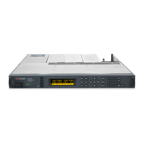
The Agilent N6700 Modular Power System – At a Glance The Agilent N6700 Modular Power System – At a Glance The Agilent N6700 Modular Power System is a configurable platform that lets you mix and match output modules to create a power system that is optimized for your test system requirements. -
Page 9: System Features
The Agilent N6700 Modular Power System – At a Glance Remote voltage Two remote sensing terminals are provided for each output. When shipped from the sensing factory, the remote sense jumpers are included in a separate bag. Refer to Chapter 2 for details. -
Page 10: The Front Panel - At A Glance
The Front Panel - At a Glance The Front Panel - At a Glance Display Navigation keys Output keys Move the cursor to a menu item. Turn the outputs on or off. Turns off after 1 hour of inactivity. Press any key to Select the highlighted menu item. -
Page 11: Front Panel Display - At A Glance
Front Panel Display – At a Glance Front Panel Display – At a Glance Single-channel View Voltage measurement Current measurement Press the Meter key to toggle between views Operating mode (CV = Voltage and Current Remote interface status constant voltage mode) settings (ALL, SRQ, ERR, IO) Multiple-channel View Voltage and Current measurements... -
Page 13: Installation
Installation General Information Inspecting the Unit Installing the Unit Connecting the Line Cord Connecting the Outputs Remote Sense Connections Parallel Connections Series Connections This chapter describes how to install your power system. It discusses installation, rack mounting, and line cord connections. This chapter discusses how to connect your load to the output terminals. -
Page 14: General Information
General Information General Information Models Agilent Model Description N6700A MPS Mainframe - without DC Power Modules N6721A – N6729A Pre-configured models for compatibility. Refer to Appendix E. N6731A 50 W 5 V DC Power Module N6732A / N6742A 50 W / 80 W 8 V DC Power Module N6733A / N6743A 50 W / 100 W 20 V DC Power Module N6734A / N6744A... -
Page 15: Inspecting The Unit
Inspecting the Unit Inspecting the Unit When you receive your power system, inspect it for any obvious damage that may have occurred during shipment. If there is damage, notify the shipping carrier and nearest Agilent Sales and Support Office immediately. Refer to Appendix D for more information. Until you have checked out the power system, save the shipping carton and packing materials in case the unit has to be returned. - Page 16 Installing the Unit The Agilent N6700 MPS can be mounted in a 19-inch EIA rack cabinet. The rack kit parts are listed at the beginning of this chapter. Install the rack mount kit as illustrated in the following figure. Step 1. Install eight clip-nuts on the rack frame (2 in each corner ) where your instrument will be located Step 2.
-
Page 17: Connecting The Line Cord
Connecting the Line Cord Bench Installation Do not block the air intake and exhaust at the sides of the unit or the exhaust at the rear of the unit. Refer to the outline diagram in Appendix A. Minimum clearances for bench operation are 2 inches (51 mm) along the sides and back. -
Page 18: Connecting The Outputs
Connecting the Outputs Connecting the Outputs SHOCK HAZARD Turn off AC power before making rear panel connections. WARNING All wires and straps must be properly connected with the terminal block screws securely tightened. Disconnect the connector plug to make your wire connections. The connector accepts wires sizes from AWG 12 to AWG 30. - Page 19 Connecting the Outputs Wire Size FIRE HAZARD Select a wire size large enough to carry short-circuit current WARNING without overheating. To satisfy safety requirements, load wires must be heavy enough not to overheat while carrying the short-circuit output current of the unit (refer to the following chart). Along with conductor temperature, you must also consider voltage drop when selecting wire sizes.
-
Page 20: Multiple Loads
Connecting the Outputs Multiple Loads If you are using local sensing and are connecting multiple loads to one output, connect each load to the output terminals using separate connecting wires (see the figure below). This minimizes mutual coupling effects and takes full advantage of the power system's low output impedance. - Page 21 Connecting the Outputs Remote Voltage Sensing Because of the unavoidable voltage drop developed in the load leads, the terminal block strapping patterns discussed thus far do not provide the best possible voltage regulation at the load. The remote sensing connections shown in the figure below improve the voltage regulation at the load by monitoring the voltage there instead of at the output terminals.
-
Page 22: Remote Sense Connections
Remote Sense Connections Remote Sense Connections Remember to turn off the power system before making or changing any connections on the rear panel terminal blocks. Connect the unit for remote sensing by first disconnecting the straps between sense and load terminals. Make your connections as shown in the previous figure. -
Page 23: Parallel Connections
Parallel Connections Parallel Connections Only outputs that have equivalent voltage and current ratings can be connected CAUTION in parallel. Connecting outputs in parallel provides a greater current capability than can be obtained from a single output. Only parallel outputs that have equivalent voltage and current capability. -
Page 24: Series Connections
Series Connections Effect on Specifications Specifications for outputs operating in parallel can be obtained from the specifications for single outputs. Most specifications are expressed as a constant or as a percentage (or ppm) plus a constant. For parallel operation, the percentage portion remains unchanged while constant portions or any constants are changed as indicated below. - Page 25 Series Connections OUTPUT 2 OUTPUT 1 OUTPUT 2 OUTPUT 1 SENSE SENSE JUMPER JUMPERS INSTALLED INSTALLED TWIST LEADS TWIST LEADS LOAD LOAD WITH LOCAL SENSING WITH REMOTE SENSING Setting the Outputs First program the current limit of each output to the total desired current limit point.
-
Page 27: Getting Started
Detailed information on configuring the remote interfaces is included in the NOTE Agilent Technologies USB/LAN/GPIB Interfaces Connectivity Guide, which you can download from the Agilent web site at http://www.agilent.com/find/connectivity... -
Page 28: Turning The Unit On
Turning the Unit On Turning the Unit On After you have connected the line cord, turn the unit on with the front panel power switch. The front panel display will light up after a few seconds. A power-on self-test occurs automatically when you turn the unit on. This test assures you that the instrument is operational. -
Page 29: Entering A Current Limit Setting
Entering a Current Limit Setting Entering a Current Limit Setting Method 1 – Use the Navigation and Arrow Keys Navigation Keys Use the left and right navigation keys to navigate to the setting that you wish to change. In the display below, channel 1’s current setting is selected. Enter a value using the numeric keypad. -
Page 30: Using The Front Panel Menu
Using the Front Panel Menu Using the Front Panel Menu The front panel command menu lets you access most of the power system’s functions. The actual function controls are located at the lowest menu level. Press the Menu key to access the command menu. Press the navigation keys to move across the menu commands. - Page 31 Using the Front Panel Menu The command menu is now at the function control level. This is the lowest level in this path. Two over-voltage function controls are available. Use the navigation keys to highlight the Enable OVP control. This control enables or disables over-voltage protection.
- Page 32 Using the Front Panel Menu Front Panel Menu Commands Menu Command Control Description Output Voltage Programs voltage setting and range. Current Programs current setting and range. Delay Program Turn-on /Turn Off delay. Measure Range Selects voltage and current measurement range. Sweep Specifies measurement points, time interval, and trigger offset.
- Page 33 Using the Front Panel Menu Menu Command Control Description System DigPort Pin 1 Function Specifies the pin function: DigIO, TrigIn, TrigOut, DigIn, or FaultOut.. Polarity Specifies the pin polarity. Pin 2 Function Specifies the pin function: DigIO, TrigIn, TrigOut, or DigIn. Polarity Specifies the pin polarity.
-
Page 34: Configuring The Interface
The Agilent N6700 MPS supports GPIB, LAN, and USB interfaces. All three interfaces are live at power-on. For detailed information about interface communication, refer to the Agilent Technologies USB/LAN/GPIB Interfaces Connectivity Guide, which you can download from the Agilent web site at http://www.agilent.com/find/connectivity... -
Page 35: Lan Interface
Configuring the Interface LAN Interface The following steps will help you quickly get started connecting and configuring your LAN-enabled instrument. If you do not have the Agilent I/O Library software installed on your PC, you can download the I/O library software from the Agilent web site at http://www.agilent.com/find/connectivity Connect your instrument to the LAN. - Page 36 Configuring the Interface Obtain DNS Automatically gets the address of the DNS server on server from your network if you have enabled DHCP in the IP DHCP menu. Use the Select this item if you are not using DHCP or need to following connect to a specific DNS server.
-
Page 37: Usb Interface
Configuring the Interface Enable TCP Keeps a LAN socket active for the specified number keepalive of seconds. This is useful to determine if a client is still reachable. If there has been no activity on the connection after the specified time, the instrument will send keepalive probes to the client to determine if it is still alive. - Page 38 Configuring the Interface You can set or change the instrument’s USB Alias name from the Edit Config dialog box on your PC. You can also do this later using IO Config. You can also use IO Config to display the USB Devices dialog box.
-
Page 39: Operating The Power System
Operating the Power System Programming the Output Synchronizing Output Steps Making Measurements System Related Operations46 Programming High-Speed Test Extensions This chapter contains examples on how to operate your power system from the front panel and over the remote interface using SCPI commands. -
Page 40: Programming The Output
Programming the Output Programming the Output Set the Output Voltage Front Panel: SCPI Command: Press the Channel key to select an To set output 1 to 5 V: output, then press the Voltage key. VOLT 5,(@1) To set all outputs to 10 V: Enter a value and press Select. - Page 41 Programming the Output Because of internal circuit start-up procedures and any installed relay options, the output on command may take between 35 and 50 milliseconds to complete its function. Conversely, the output off command may take between 20 and 25 milliseconds to complete its function.
-
Page 42: Synchronizing Output Steps
Synchronizing Output Steps Clear Output Protection Functions If an over-voltage, over-current, over-temperature, inhibit signal, or a power-fail condition occurs, the power system turns off the affected output channel. The PROT annunciator on the front panel will be on. To clear the protection function and restore normal operation, first remove that condition that caused the protection fault. - Page 43 Synchronizing Output Steps Set the Voltage or Current Trigger Levels Next, use the following commands to program an output trigger level. The output will go to this level when the trigger is received. If you have a model that has multiple ranges, the selected triggered voltage and current settings must be within the same range that the output channel is presently operating in.
- Page 44 Synchronizing Output Steps Initiate the Transient Trigger System Next, you must initiate or enable the transient trigger system. When the power system is turned on, the trigger system is in the idle state. In this state, the trigger system is disabled, ignoring all triggers. Initiating the trigger system moves it from the idle state to the initiated state, which enables the power system to receive triggers.
-
Page 45: Making Measurements
Making Measurements Generating Trigger Out Signals Each output channel can generate trigger signals that can be used by other output channels, or routed to a pin on the digital port that has been configured as a trigger output (TOUT). Use the following commands to program transient trigger signals that are generated when an output Step occurs: Front Panel:... -
Page 46: System Related Operations
System Related Operations Measurement Ranges Some models have two voltage and current measurement ranges. Refer to Chapter 1, “Model Differences” for model-specific information. Selecting a lower measurement range provides greater measurement accuracy, provided that the measurement does not exceed the range. The commands that control the ranges are: Front Panel: SCPI Command: Select Measure\Range. - Page 47 System Related Operations Instrument State Storage The power system has two storage locations in non-volatile memory to store instrument states. The locations are numbered 0 and 1. Any state previously stored in the same location will be overwritten. Front Panel: SCPI Command: Select States\SaveRecall.
- Page 48 System Related Operations Front Panel: SCPI Command: Select Not Available. System\Preferences\Display Enable or disable the screen saver by checking the Screen Saver checkbox. Then Press Select. Enter a value in minutes in the Saver Delay field to specify the time when the screen saver will activate.
-
Page 49: Programming High-Speed Test Extensions
Programming High-Speed Test Extensions Programming High-Speed Test Extensions The High-Speed Test Extensions described in this section are not available on NOTE all models. Refer to Chapter 1, “Model Differences” for model-specific information. The List Function Either output voltage or output current, or both together, may be list- controlled. - Page 50 Programming High-Speed Test Extensions Program an Output Pulse or Pulse Train The following procedure shows how to generate an output pulse train using the List function. Trigger Pulse width List Count = 1+additional pulses time Step 1. Set the voltage or current function for which you want to generate a pulse to List mode.
- Page 51 Programming High-Speed Test Extensions Step 5. To generate a pulse train, you can simply repeat the pulse as needed. For example, to program a pulse train of 50 pulses, use: Front Panel: SCPI Command: Select Transient\List\Repeat. To program output 1, use Enter the number of list repetitions LIST:COUN 50, (@1) (50) and Press Select.
- Page 52 Programming High-Speed Test Extensions Program an Arbitrary List The following procedure shows how to generate the list of voltage changes as illustrated in the following figure. Trigger List Count = 1 List Count = 2 Step 1. Set the function, voltage or current, for which you want to generate a list to List mode.
- Page 53 Programming High-Speed Test Extensions Front Panel: SCPI Command: Select Transient\List\Pace. LIST:STEP AUTO, (@1) Select Dwell-paced. Press Select. In a trigger-paced list, the list advances one step for each trigger received. To enable trigger-paced lists, select Trigger-paced on the front panel menu. (Set the LIST:STEP command to ONCE.) The dwell time associated with each step determines the minimum time that the output remains at the step.
- Page 54 Programming High-Speed Test Extensions The Digitizer Function The digitizer function lets you access the enhanced voltage and current measurement capabilities of the power system. These include: Adjusting the measurement sample rate - to a maximum of 50 kHz. Adjusting measurement triggers to capture pre-trigger transients. Selecting a measurement window that can attenuate ac noise.
- Page 55 Programming High-Speed Test Extensions 4096 DATA POINTS OFFSET = -4095 4096 DATA POINTS OFFSET = -2048 4096 DATA POINTS OFFSET = 0 OFFSET = 0 to 2 4096 DATA POINTS TIME TRIGGER To offset the beginning of the acquisition buffer relative to the acquisition trigger, use: Front Panel: SCPI Command:...
- Page 56 Programming High-Speed Test Extensions To select a window function, use: Front Panel: SCPI Command: Select Measure\Window. To set the sense window to Hanning for output 1 use: Then select either Rectangular or Hanning and press Select. SENS:WIND HANN, (@1) Retrieve Measurement Array Data Array queries return all values in the voltage and current measurement buffer.
- Page 57 Programming High-Speed Test Extensions To trigger measurements on output modules that do not have simultaneous voltage and current measurement capability, select the measurement function as follows. Front Panel: SCPI Command: Not Available To select the measurement function: SENS:FUNC ”VOLT”,(@1:4) SENS:FUNC ”CURR”,(@1:4) If a model has simultaneous voltage and current measurements capability, then BOTH voltage and current are acquired on any triggered measurement, regardless of the setting of the...
- Page 58 Programming High-Speed Test Extensions Initiate the Measurement Trigger System Next, you must initiate or enable the measurement trigger system. When the power system is turned on, the trigger system is in the idle state. In this state, the trigger system is disabled, ignoring all triggers. The INITiate commands enable the measurement system to receive triggers.
-
Page 59: Introduction To Programming
Introduction to Programming SCPI Commands SCPI Messages SCPI Conventions and Data Formats SCPI Command Completion Device Clear This chapter contains a brief introduction to the SCPI Programming language. SCPI (Standard Commands for Programmable Instruments) is a programming language for controlling instrument functions over the GPIB. -
Page 60: Scpi Commands
SCPI Commands SCPI Commands SCPI has two types of commands, common and subsystem. Common commands generally control overall power system functions, such as reset, status, and synchronization. All common commands consist of a three-letter mnemonic preceded by an asterisk: *RST *IDN? *SRE 8 Subsystem commands perform specific power system functions. - Page 61 SCPI Commands defined as "OUTPut" and thus the instrument interpreted the second command as: OUTPut:PROTection:CLEar (@1) In fact, it would have been syntactically incorrect to include the "OUTP" explicitly in the second command, since the result after combining it with the header path would be: OUTPut:OUTPut:PROTection:CLEar (@1) which is incorrect.
-
Page 62: Scpi Messages
SCPI Messages Coupled Commands When commands are coupled it means that the value sent by one command is affected by the settings of another command. The following commands are coupled: [SOURce:]CURRent and [SOURce:]CURRent:RANGe. [SOURce:]VOLTage and [SOURce:]VOLTage:RANGe. If a range command is sent that places an output on a range with a lower maximum setting than the present level, an error is generated. - Page 63 SCPI Messages The Message Unit The simplest SCPI command is a single message unit consisting of a command header (or keyword) followed by a message terminator. The message unit may include a parameter after the header. The parameter can be numeric or a string. ABORt<NL>...
-
Page 64: Scpi Conventions And Data Formats
SCPI Conventions and Data Formats Message Unit Separator When two or more message units are combined into a compound message, separate the units with a semicolon. STATus:OPERation?(@1);QUEStionable?(@1) Root Specifier When it precedes the first header of a message unit, the colon becomes the root specifier. -
Page 65: Data Formats
SCPI Conventions and Data Formats Data Formats Data programmed or queried from the power system is ASCII. The data may be numerical or character string. Numeric Data Formats Symbol Response Formats <NR1> Digits with an implied decimal point assumed at the right of the least- significant digit. -
Page 66: Scpi Command Completion
SCPI Command Completion SCPI Command Completion SCPI commands sent to the power system are processed either sequentially or in parallel. Sequential commands finish execution before a subsequent command begins. Parallel commands allow other commands to begin executing while the parallel command is still executing. -
Page 67: Language Dictionary
Language Dictionary SCPI Command Summary Calibration Subsystem Measurement Subsystem Output Subsystem Source Subsystem Status Subsystem System Commands Trigger Subsystem This section gives the syntax and parameters for all the IEEE 488.2 SCPI commands and the Common commands used by the power system. -
Page 68: Scpi Command Summary
SCPI Command Summary SCPI Command Summary Subsystem Commands Some [optional] commands have been included for clarity. NOTE SCPI Command Description ABORt :ACQuire (@chanlist) Resets the measurement trigger system to the Idle state :TRANsient (@chanlist) Resets the transient trigger system to the Idle state CALibrate :CURRent [:LEVel] <NRf>, (@channel) - Page 69 SCPI Command Summary SCPI Command Description OUTPut (continued) :PROTection :CLEar (@chanlist) Resets latched protection :COUPle <Bool> Enables/disables channel coupling for protection faults :DELay <NRf+>, (@chanlist) Sets over-current protection programming delay :RELay [:STATe] <Bool>, (@chanlist) Sets the relay state independently of the output state (Note 3) SENSe :CURRent [:DC] :RANGe [:UPPer] <NRf+>, (@chanlist)
- Page 70 SCPI Command Summary SCPI Command Description [SOURce:] (continued) VOLTage [:LEVel] [:IMMediate][:AMPLitude] <NRf+>, (@chanlist) Sets the output voltage :TRIGgered [:AMPLitude] <NRf+>, (@chanlist) Sets the triggered output voltage :MODE FIXed | STEP | LIST, (@chanlist) Sets the voltage trigger mode :PROTection [:LEVel] <NRf+>, (@chanlist) Sets the over-voltage protection level :RANGe <NRf+>, (@chanlist) Sets the output voltage range (Note 4)
-
Page 71: Common Commands
SCPI Command Summary Common Commands Command Description Command Description *CLS Clear status *RDT? Return output channel descriptions *ESE <NRf> Standard event status enable *RST Reset *ESE? Return standard event status enable *SAV <NRf> Saves an instrument state *ESR? Return event status register *SRE <NRf>... -
Page 72: Calibration Subsystem
Calibration Subsystem Calibration Subsystem The calibration subsystem lets you calibrate the power system. Refer to Appendix B for details. If calibration mode has not been enabled with CALibrate:STATe, the calibration NOTE commands will generate an error. Use CALibrate:SAVE to save any changes, otherwise all changes will be lost when you exit calibration mode. - Page 73 Calibration Subsystem Some calibration sequences may require some settling time after sending NOTE CAL:LEV but before reading the data from the DVM and sending CAL:DATA. CALibrate:PASSword <password> This command lets you change the calibration password. A new password is automatically stored in nonvolatile memory and does not have to be stored with CALibrate:SAVE.
-
Page 74: Measurement Subsystem
Measurement Subsystem Measurement Subsystem The measurement subsystem consists of Measure, Fetch, and Sense commands. Measure commands measure the output voltage or current. They trigger the acquisition of new data before returning the reading. Measurements are performed by digitizing the instantaneous output voltage or current for a specified time interval, storing the results in a buffer, and calculating the average value. - Page 75 Measurement Subsystem FETCh[:SCALar]:CURRent[:DC]? (@<chanlist>) FETCh[:SCALar]:VOLTage[:DC]? (@<chanlist>) MEASure[:SCALar]:CURRent[:DC]? (@<chanlist>) MEASure[:SCALar]:VOLTage[:DC]? (@<chanlist>) These queries return the DC output current in amperes or output voltage in volts. The data returned by the FETCh command is the result of the last acquisition. The data is valid until the next MEASure or INITiate command occurs.
- Page 76 Measurement Subsystem SENSe:SWEep:POINts {<points>|MIN|MAX}, (@<chanlist>) SENSe:SWEep:POINts? (@<chanlist>) This command defines the number of points in a measurement on models that have measurement controls. Programmed values can range from 1 to 4096. The *RST value = 1024. SENSe:SWEep:TINTerval {<interval>|MIN|MAX}, (@<chanlist>) SENSe:SWEep:TINTerval? (@<chanlist>) This command defines the time period between samples in seconds on models that have measurement controls.
-
Page 77: Output Subsystem
Output Subsystem Output Subsystem The Output subsystem controls the output, power-on, protection, and relay functions. OUTPut[:STATe] {ON|OFF}, [NORelay],(@<chanlist>) OUTPut[:STATe]? (@<chanlist>) This command enables or disables the specified output channel(s). The enabled state is ON (1); the disabled state is OFF (0). The state of a disabled output is a condition of zero output voltage and a zero source current. - Page 78 Output Subsystem OUTPut[:STATe]:DELay:RISE {<delay>|MIN|MAX}, (@<chanlist>) OUTPut[:STATe]:DELay:RISE? (@<chanlist>) This command sets the delay in seconds that the instrument waits before enabling the specified output. It affects all off-to-on transitions including changes in the OUTPut:STATe as well as transitions due to OUTPut:PROTection:CLEar. Delay times can range from 0 to 1.023 seconds in increments of 1 millisecond.
- Page 79 Output Subsystem OUTPut:PROTection:CLEar (@<chanlist>) This command clears the latched protection status that disables the output when an over-voltage, over-temperature, over-current, power- fail, or Inhibit status condition is detected. All conditions that generate the fault must be removed before the latched status can be cleared.
-
Page 80: Source Subsystem
Source Subsystem Source Subsystem The Source subsystem programs the current, digital, list, step, and voltage functions. The SOURce:CURRent:RANge, SOURce:VOLTage:RANge, and SOURce:LIST NOTE commands do not apply to all models. Refer to Chapter 1, “Model Differences” for model-specific information. [SOURce:]CURRent[:LEVel][:IMMediate][:AMPLitude] {<value>|MIN|MAX}, (@<chanlist>) [SOURce:]CURRent[:LEVel][:IMMediate][:AMPLitude]? (@<chanlist>) [SOURce:]CURRent[:LEVel]:TRIGgered[:AMPLitude] {<value>|MIN|MAX}, (@<chanlist>) - Page 81 Source Subsystem [SOURce:]CURRent:RANGe {<value>|MIN|MAX}, (@<chanlist>) [SOURce:]CURRent:RANGe? (@<chanlist>) This command only applies to models that have programmable ranges. Refer to Appendix A for the available ranges for each model. This command sets the output current range. Units are in amperes. The instrument selects the range with the best resolution for the value entered.
- Page 82 Source Subsystem [SOURce:]DIGital:PIN1:FUNCtion {DIO|DINPut|TOUTput|TINPut|FAULt} [SOURce:]DIGital:PIN1:FUNCtion? [SOURce:]DIGital:PIN2:FUNCtion {DIO|DINPut|TOUTput|TINPut} [SOURce:]DIGital:PIN2:FUNCtion? [SOURce:]DIGital:PIN3:FUNCtion { DIO|DINPut|TOUTput|TINPut|INHibit [SOURce:]DIGital:PIN3:FUNCtion? These commands set the functions of the three digital port pins. The pin functions are saved in non-volatile memory. DIO The pin is a general-purpose ground-referenced digital input/output. The output can be set with DIGital:OUTPut:DATA <value>.
- Page 83 Source Subsystem [SOURce:]LIST:COUNt {<count>|MIN|MAX|INFinity}, (@<chanlist>) [SOURce:]LIST:COUNt? (@<chanlist>) This command sets the number of times that the list is executed before it is completed. Applies only to models with list capability. The range is 1 through 256. Use INFinity to execute a list indefinitely. In this case, use ABORt:TRANsient to stop the list.
- Page 84 Source Subsystem [SOURce:]LIST:DWELl:POINts? (@<chanlist>) This query returns the number of points (steps) in the dwell list. Applies only to models with list capability. [SOURce:]LIST:STEP {ONCE|AUTO}, (@<chanlist>) [SOURce:]LIST:STEP? (@<chanlist>) This command specifies how the list responds to triggers. Applies only to models with list capability. ONCE Causes the output to remain at the present step until a trigger advances it to the next step.
- Page 85 Source Subsystem [SOURce:]LIST:VOLTage[:LEVel] <volt> {,<volt>}, (@<list>) [SOURce:]LIST:VOLTage[:LEVel]? (@<chanlist>) This command specifies the voltage setting for each list step in volts. Applies only to models with list capability. Up to 512 steps may be programmed. The values are separated by commas. The *RST value = 1 step with a value of MIN.
- Page 86 Source Subsystem [SOURce:]VOLTage:PROTection:LEVel {<value>|MIN|MAX}, (@<chanlist>) [SOURce:]VOLTage:PROTection:LEVel? (@<chanlist>) This command sets the over-voltage protection (OVP) level of the output channel. The values are programmed in volts. If the output voltage exceeds the OVP level, the output is disabled and the Questionable Condition status register OV bit is set. An over-voltage condition can be cleared with the Output Protection Clear command after the condition that caused the OVP trip is removed.
-
Page 87: Status Subsystem
Status Subsystem Status Subsystem Status register programming lets you determine the operating condition of the power system at any time. The power system has three groups of status registers; Operation, Questionable, and Standard Event. The Operation and Questionable status groups each consist of the Condition, Enable, and Event registers as well as NTR and PTR filters. - Page 88 Status Subsystem does a serial poll, RQS is cleared inside the register and returned in bit position 6 of the response. The remaining bits of the Status Byte register are not disturbed. MAV Bit and Output Queue The Output Queue is a first-in, first-out (FIFO) data register that stores power system-to-controller messages until the controller reads them.
- Page 89 Status Subsystem STATus:PRESet This command sets all defined bits in the Status system’s PTR registers and clears all bits in the NTR and Enable registers. Operation Register Questionable Register Preset Settings STAT:OPER:ENAB STAT:QUES:ENAB 0 all bits disabled STAT:OPER:NTR STAT:QUES:NTR 0 all bits disabled STAT:OPER:PTR 31 all defined bits enabled STAT:QUES:PTR...
- Page 90 Status Subsystem STATus:OPERation:NTRansition <value>, (@<chanlist>) STATus:OPERation:PTRansition <value>, (@<chanlist>) STATus:OPERation:NTRansition? (@<chanlist>) STATus:OPERation:PTRansition? (@<chanlist>) These commands set and read the value of the Operation NTR (Negative-Transition) and PTR (Positive-Transition) registers. These registers serve as polarity filters between the Operation Condition and Operation Event registers to cause the following actions: When a bit in the Operation NTR register is set to 1, then a 1-to-0 transition of the corresponding bit in the Operation Condition register causes that bit in the Operation Event register to be set.
- Page 91 Status Subsystem STATus:QUEStionable:ENABle <value>, (@<chanlist>) STATus:QUEStionable:ENABle? (@<chanlist>) This command and its query set and read the value of the Questionable Enable register. This register is a mask for enabling specific bits from the Questionable Event register to set the questionable summary bit (QUES) of the Status Byte register. This bit (bit 3) is the logical OR of all the Questionable Event register bits that are enabled by the Questionable Status Enable register.
- Page 92 Status Subsystem *ESE *ESE? This command programs the Standard Event Status Enable register bits. The programming determines which events of the Standard Event Status Event register (see *ESR?) are allowed to set the ESB (Event Summary Bit) of the Status Byte register. A "1" in the bit position enables the corresponding event.
- Page 93 Status Subsystem *SRE *SRE? This command sets the value of the Service Request Enable Register. This register determines which bits from the Status Byte Register are summed to set the Master Status Summary (MSS) bit and the Request for Service (RQS) summary bit. A 1 in any Service Request Enable Register bit position enables the corresponding Status Byte Register bit.
-
Page 94: System Commands
System Commands System Commands System commands control system functions that are not directly related to output control, measurement, or status functions. Common commands are also used to control system functions. SYSTem:CHANnel[:COUNt]? This query returns the number of output channels installed in a mainframe. - Page 95 This query requests the power system to identify itself. It returns a string of four fields separated by commas. Field Information Agilent Technologies Manufacturer N67xxA Mainframe model number followed by a letter suffix Zero or Mainframe serial number if available <A>.xx.xx...
- Page 96 System Commands *RDT? This query returns a description of the output channels installed in a mainframe. Semicolons separate multiple channel descriptions. Field Information CHAN <c> Channel number description Description of the output channel *RST This command resets the volatile memory of the power system to a factory-defined state (see “*RST Settings”...
-
Page 97: Trigger Subsystem
Trigger Subsystem Trigger Subsystem The Trigger subsystem consists of the Abort, Initiate, and Trigger commands. Abort commands cancel any triggered actions. Initiate commands initialize the trigger system. This enables the trigger system to receive triggers. Trigger commands control the remote triggering of the power system. They specify the trigger source for the transient and the measurement system and also generate software triggers. - Page 98 Trigger Subsystem GPIB device trigger, *TRG, or <GET> (Group Execute Trigger). PIN<pin> Selects an output port connector pin. Pins 1 – 3 can be configured as external trigger sources. The [SOURce:]DIGital:PIN<n>:FUNCtion command programs the function of each pin. The [SOURce:]DIGital:PIN<n>:POLarity command programs the polarity of each pin.
-
Page 99: Programming Examples
You have a royalty-free right to use, modify, reproduce and distribute the example programs (and/or any modified version) in any way you find useful, provided that you agree that Agilent Technologies has no warranty, obligations, or liability for any example programs. -
Page 100: Output Programming Example
Output Programming Example Output Programming Example This is a simple program that sets a voltage, current, over-voltage, and the status of over-current protection. When done, the program checks for instrument error and gives a message if there is an error. Sub main_List() Dim IDN As String Dim GPIBaddress As String... - Page 101 Output Programming Example With Instrument ' Send a power reset to the instrument .WriteString "*RST" ' Query the instrument for the IDN string .WriteString "*IDN?" IDN = .ReadString ' Set voltage .WriteString "VOLT" & Str$(VoltSetting) & "," & channel ' Set the over voltage level .WriteString "VOLT:PROT:LEV "...
-
Page 102: List Programming Example
List Programming Example List Programming Example This program executes a 10 point current and voltage list. It also specifies 10 different dwell times. When done the program checks for instrument error and gives a message if there is an error. For ease in reading, error checking is not included. - Page 103 List Programming Example ' Send the voltage list points .WriteString "LIST:VOLT " & voltPoints & "," & channel ' Send the Current list points .WriteString "LIST:CURR " & currPoints & "," & channel ' Send the dwell points .WriteString "LIST:DWEL " & dwellPoints & "," & channel ' Turn the output on .WriteString "OUTP ON,"...
-
Page 104: Digitizer Programming Example
Digitizer Programming Example Digitizer Programming Example This program uses the voltage in step mode and also demonstrates how to set up and use the digitizer. Sub main_List() Dim IDN As String Dim GPIBaddress As String Dim ErrString As String Dim channel As String Dim measPoints As Long Dim measOffset As Long Dim Voltage As Double... - Page 105 Digitizer Programming Example IDN = .ReadString ' Put the Voltage into step mode which causes it to transition from one ' voltage to another upon receiving a trigger .WriteString "VOLT:MODE STEP," & channel ' program to voltage setting .WriteString "VOLT" & Str$(Voltage) & "," & channel ' Go to final value .WriteString "VOLT:TRIG"...
-
Page 107: A Specifications
Specifications Performance Specifications Supplemental Characteristics Auto-Ranging Characteristic Outline Diagram This chapter lists the specifications and supplemental characteristics of the Agilent N6700 Modular Power System. A dimensional line drawing of the mainframe is included at the end of the chapter. Unless otherwise noted, specifications are warranted over the ambient temperature range of 0 to 55°C. -
Page 108: Performance Specifications
Performance Specifications Performance Specifications Agilent Models N6751A/N6752A and N6761A/N6762A N6751A / N6752A N6761A / N6762A DC Output Ratings: Voltage 50 V 50 V Current (derated 1% per °C above 40°C) 5 A / 10A 1.5 A / 3 A Power 50 W / 100 W 50 W / 100 W Output Ripple and Noise (PARD):... - Page 109 Performance Specifications Agilent Models N6731A - N6735A and N6742A - N6745A N6731A N6732A/N6742A N6733A/N6743A N6734A/N6744A N6735A/N6745A DC Output Ratings: Voltage 20 V 35 V 50 V Current 10 A 6.25 A / 10 A 2.5 A / 5 A 1.5 A / 3 A 0.8 A / 1.6 A NOTE 1 Power...
-
Page 110: Supplemental Characteristics
Supplemental Characteristics Supplemental Characteristics Agilent Models N6751A/N6752A and N6761A/N6762A N6751A / N6752A N6761A / N6762A Programming Ranges: Voltage high range 20 mV – 51 V 15 mV – 51 V 12 mV – 5.5 V Voltage low range (≤ 5.5 V) Current high range 10 mA - 5.1A/10 mA- 10.2A 1 mA - 1.53 A/1 mA - 3.06 A... - Page 111 Supplemental Characteristics Agilent Models N6751A/N6752A and N6761A/N6762A (continued) N6751A / N6752A N6761A / N6762A Maximum Up-programming Time with full resistive load: (time f rom 10% to 90% of total voltage excursion) Voltage setting from 0 V to 10 V 0.2 ms 0.6 ms Voltage setting from 0 V to 50 V 1.5 ms...
- Page 112 Supplemental Characteristics Agilent Models N6751A/N6752A and N6761A/N6762A Output Impedance Graphs Phase Phase Magnitude Magnitude 1.25 100k 100k FREQUENCY (Hz) FREQUENCY (Hz) Model N6752A, CV Mode, @50V, 2A Model N6762A, CV Mode, @50V, 2A Magnitude Magnitude Phase Phase 0.25 0.25 0.125 0.125 0.062 100k...
- Page 113 Supplemental Characteristics Agilent Models N6731A - N6735A and N6742A - N6745A N6731A N6732A/N6742A N6733A/N6743A N6734A/N6744A N6735A/N6745A Programming Ranges: Voltage 20 mV – 5.1 V 20 mV – 8 .16 V 20 mV – 20.4 V 20 mV – 35.7 V 20 mV –...
- Page 114 Supplemental Characteristics Agilent N6700A MPS Mainframe N6700A Command Processing Time: From receipt of command to start of the ≤ 1 ms output change Protection Response Characteristics: INH input 5 µs from receipt of inhibit to start of shutdown Fault on coupled outputs <...
- Page 115 Supplemental Characteristics Agilent N6700A MPS Mainframe N6700A Regulatory Compliance: Complies with the European EMC directive 89/336/EEC for Class A test and measurement products. Complies with the Australian standard and carries the C-Tick mark. This ISM device complies with Canadian ICES-001. Cet appareil ISM est conforme à...
-
Page 116: Auto-Ranging Characteristic
Outline Diagram Auto-Ranging Characteristic Voltage Voltage Voltage Autoranging Autoranging Precision 50 W Output 100 W Output Outputs 50 V 50 V 50 V 50 W curve 100 W curve 33 V 12 V 10 V Current 8.5 V Current Current 8.33 A 10 A 1.5 A... -
Page 117: B Verification And Calibration
Verification and Calibration Verification Calibration The verification procedures described in this appendix verify that the power system is operating normally and is within published specifications. This appendix also includes calibration procedures for the Agilent N6700 MPS. Instructions are given for performing the procedures either from the front panel or from a controller over the GPIB. -
Page 118: Verification
If the power system fails any of the tests or if abnormal test results are obtained, try calibrating the unit. If calibration is unsuccessful, return the unit to an Agilent Technologies repair facility (see Appendix D). Equipment Required The equipment listed in the following table, or the equivalent to this equipment, is required for the calibration and performance tests. - Page 119 Verification Measurement Techniques Electronic Load Many of the test procedures require the use of a variable load capable of dissipating the required power. If a variable resistor is used, switches should be used to either; connect, disconnect, or short the load resistor.
- Page 120 Verification Constant Voltage Tests Test each output channel individually. Refer to the appropriate test record form NOTE for the instrument settings of the model you are checking. Voltage Programming and Readback Accuracy Test category = performance, calibration This test verifies that the voltage programming and measurement functions are within specifications.
- Page 121 Verification Open the load. Record the voltage reading from the DVM again. The difference between the DVM readings in steps 4 and 5 is the load effect, which should not exceed the value listed in the test record form for the appropriate model under “CV Load Effect”. CV Source Effect Test category = performance This test measures the change in output voltage that results from a...
- Page 122 Verification Set the differential amplifier to multiply by ten, divide by one, and 1 Megohm input resistance. The positive and negative inputs of the differential amplifier should be set to AC coupling. Set the oscilloscope’s time base to 5 ms/div, and the vertical scale to 10 mV/div.
- Page 123 Verification Loading tttt Transient Unloading Transient Constant Current Tests Test each output channel individually. Refer to the appropriate test record form NOTE for the instrument settings of the model you are checking. Current Programming and Readback Accuracy Test category = performance, calibration This test verifies that the current programming and measurement functions are within specifications.
- Page 124 Verification CC Load Effect Test category = performance This test measures the change in output current resulting from a change in output voltage from full scale to short circuit. Turn off the power system and connect the current shunt, DVM, and electronic load as shown in Test Setup figure (B).
- Page 125 Verification Turn on the power system and program the instrument settings as described in the test record form under “CC Source Effect”. Set the electronic load for the output channel’s voltage under “CC Source Effect”. The CC annunciator on the front panel must be on.
- Page 126 Verification Test Record Form – Agilent N6751A and N6752A Agilent N6751A and N6752A Report No _______________ Date __________________ Description Model Minimum Specs. Results Maximum Specs. Constant Voltage Tests Voltage Programming & Readback Minimum Voltage Vout Both + 1 mV __________ + 39 mV Front Panel Display Readback Both...
- Page 127 Verification Test Record Form – Agilent N6761A and N6762A Agilent N6761A and N6762A Report No _______________ Date __________________ Description Model Minimum Specs. Results Maximum Specs. Constant Voltage Tests High Range Voltage Prog. & Readback Minimum Voltage Vout Both + 9 mV __________ + 21 mV Front Panel Display Readback...
- Page 128 Verification Test Record Form – Agilent N6731A Agilent N6731A Report No _______________ Date __________________ Description Model Minimum Specs. Results Maximum Specs. Constant Voltage Tests Voltage Programming & Readback Minimum Voltage Vout + 1 mV __________ + 39 mV Front Panel Display Readback Vout −...
- Page 129 Verification Test Record Form – Agilent N6732A and N6742A Agilent N6732A and N6742A Report No _______________ Date __________________ Description Model Minimum Specs. Results Maximum Specs. Constant Voltage Tests Voltage Programming & Readback Minimum Voltage Vout Both + 1 mV __________ + 39 mV Front Panel Display Readback Both...
- Page 130 Verification Test Record Form – Agilent N6733A and N6743A Agilent N6733A and N6743A Report No _______________ Date __________________ Description Model Minimum Specs. Results Maximum Specs. Constant Voltage Tests Voltage Programming & Readback Minimum Voltage Vout Both 0 mV __________ + 40 mV Front Panel Display Readback Both Vout −...
- Page 131 Verification Test Record Form – Agilent N6734A and N6744A Agilent N6734A and N6744A Report No _______________ Date __________________ Description Model Minimum Specs. Results Maximum Specs. Constant Voltage Tests Voltage Programming & Readback Minimum Voltage Vout Both − 15 mV __________ + 55 mV Front Panel Display Readback Both...
- Page 132 Verification Test Record Form – Agilent N6735A and N6745A Agilent N6735A and N6745A Report No _______________ Date __________________ Description Model Minimum Specs. Results Maximum Specs. Constant Voltage Tests Voltage Programming & Readback Minimum Voltage Vout Both − 40 mV __________ + 80 mV Front Panel Display Readback Both...
-
Page 133: Calibration
Calibration Calibration Refer to the “Equipment Required” section in this appendix for a list of the equipment required for calibration. A general outline of the procedure is as follows: Enter the calibration mode by providing the correct password. The password is set at the factory to 0 (zero). You can change the password once calibration mode is entered. - Page 134 Calibration Calibration Procedure Unless instructed otherwise, connect the +sense terminal to the +output, and the -sense terminal to the -output. Warm-up Period for Agilent Models N6761A and N6762A Agilent Models N6761A and N6762A require a warm-up period of 30 minutes in the reset (*RST) state before starting the calibration procedure.
- Page 135 Calibration Step 6. Measure the output voltage with the DVM and enter the data. Front Panel: SCPI Command: Select the Measured Data field. Enter CAL:DATA <data> the data from the external DVM. Press Select when done. Press Next to finish calibration. Low Range Voltage Programming Calibration This only applies to Agilent Models N6761A and N6762A.
- Page 136 Calibration Low Range Voltage Measurement Calibration This only applies to Agilent Models N6761A and N6762A. Step 12. Select the low-voltage measurement range. This example selects the 5 volt measurement range of channel 1. The value to program a range must be the maximum voltage of the range. Front Panel: SCPI Command: Select...
- Page 137 Calibration Front Panel: SCPI Command: Select CAL:VOLT:CMRR (@1) System\Cal\Sequences\CMRR. *OPC? Then select Next. Current Programming and Measurement Calibration Step 1. Connect a precision shunt resistor to an output channel. Connect the DVM to measure the voltage across the shunt. The shunt resistor should be able to measure at least 120% of the channel’s rated full- scale current.
- Page 138 Calibration Low Range Current Programming Calibration This only applies to Agilent Models N6761A and N6762A. Step 7. Connect a precision shunt resistor to an output channel. Connect the DVM to measure the voltage across the shunt. The shunt resistor should be able to measure at least 120% of the rated output current of this current range.
- Page 139 Calibration Low Range Current Measurement Calibration This only applies to Agilent Models N6761A and N6762A. Step 13. Remove all loads from the output and turn the output off. Wait a minimum of 3 minutes with the output off before proceeding. Step 14.
- Page 140 Calibration Current Downprogrammer Calibration Step 19. Remove all loads from the output. This procedure is automatic and takes a few seconds. Front Panel: SCPI Command: Select CAL:DPRog (@1) *OPC? System\Cal\Sequences\DPprog. Then select Next. Peak Current Limit Calibration Steps 20 through 24 only apply to Agilent Models N6751A, N6752A, N6761A and N6762A.
- Page 141 Calibration Step 27. Select the first current calibration point. Front Panel: SCPI Command: Select Next. The calibration is CAL:LEV P1 automatic. *OPC? Save and Exit Calibration Mode Storing calibration constants overwrites the existing ones in non-volatile CAUTION memory. If you are not sure you want to permanently store the new constants, do not Save the data when you exit the calibration mode.
-
Page 143: C Using The Digital Port
Using the Digital Port Digital Control Port Configuring the Digital Control Port A Digital Control Port consisting of three I/O pins is provided to access various control functions. Each pin is user-configurable. The following control functions are available for the I/O pins: External Trigger Fault Output Inhibit Input... -
Page 144: Digital Control Port
Digital Control Port Digital Control Port A 4-pin connector and a quick-disconnect connector plug are provided on each instrument for accessing the five digital control port functions. TIGHTEN SCREWS Pin 1 INSERT WIRES Pin 2 Signal Common Pin 3 The digital control connector accepts wires sizes from AWG 14 to AWG 30. - Page 145 Digital Control Port External Trigger Any of the Digital Control pins can be programmed to function either as trigger inputs or trigger outputs. All three pins are referenced to the Signal Common pin. To input an external trigger signal, you can either apply a negative-or a positive-going pulse to the designated trigger input pin.
- Page 146 Digital Control Port Fault/Inhibit System Protection The following figure illustrates some ways that you can connect the Fault/Inhibit pins of the connector. Panic switch Input Common As shown in the previous figure, when the Fault outputs and Inhibit inputs of several mainframes are daisy-chained, an internal fault condition in one of the mainframes will disable all of them without intervention either by the controller or external circuitry.
- Page 147 Digital Control Port 16.5 V max Coil Current 100 mA max Digital Output Ports 0, 1, 2 TTL, AS, CMOS, HC Relay driver Ports 0, 1, 2. (contains internal clamp diodes for inductive flyback) Digital Input Ports 0, 1, 2 A) Relay Circuits B) Digital Interface Circuits Digital Input Only...
-
Page 148: Configuring The Digital Control Port
Configuring the Digital Control Port Configuring the Digital Control Port You can configure the Digital Control pins to perform five different functions. These pins can be programmed either from the front panel or using SCPI commnds. External Trigger Each of the three pins can be configured as either trigger inputs or trigger outputs. -
Page 149: Digital Input
Configuring the Digital Control Port After you have configured pin 3 as the remote inhibit input, you must also configure the operating mode of the Inhibit signal. The inhibit signal can be latched or live. When latched, the outputs will remain disabled after an inhibit signal is received. -
Page 151: D Service
Types of Service Available Operating Checklist Repackaging for Shipment Disassembly Error Messages This chapter discusses the procedures involved for returning a failed instrument to Agilent Technologies for service or repair. Actual repair is done through unit exchange. Series N6700 User’s Guide... -
Page 152: Types Of Service Available
Turn off the unit and cycle power to run self-test again. Repackaging for Shipment If the unit is to be shipped to Agilent Technologies for service or repair, be sure to: Attach a tag to the unit identifying the owner and indicating the required service or repair. -
Page 153: Disassembly
Disassembly Disassembly Electrostatic Discharge (ESD) Precautions Almost all electrical components can be damaged by electrostatic discharge (ESD) during handling. Component damage can occur at electrostatic discharge voltages as low as 50 volts. The following guidelines will help prevent ESD damage when servicing the instrument or any electronic device. - Page 154 Disassembly Step 4. Fasten the module to the mainframe. Use the two screws from the power module or filler module and install them at either end of the module. Step 5. Replace the blower cover when finished. Be careful not to bend the RFI clips on the edge of the cover when sliding it under the lip of the output modules.
- Page 155 Disassembly Accessing the Calibration switch SHOCK HAZARD. FAN HAZARD. Turn off the mainframe and disconnect its WARNING power cord before attempting any of the following procedures. Step 1. Remove the blower cover (cover is shown in the previous figure). Remove three screws from the top of the cover and two screws on the sides.
-
Page 156: Error Messages
Error Messages Error Messages Displaying the SCPI error queue Front Panel: SCPI Command: Press the Error key. SYST:ERR? If errors appear, use the navigation keys to scroll though the list. The entire error queue is read, then emptied. Error List The following table documents the various error messages that the power system supports: Error... - Page 157 Error Messages Device-dependent Errors (continued) Hardware error channel <channel> A hardware error has occurred on the specified channel. Invalid configuration, empty slots There is an empty slot between modules. This configuration is not allowed. Selftest Fail A selftest failure has occurred. See selftest failure list for details. Compatibility function not implemented The requested compatibility function is not available.
- Page 158 Error Messages Command Errors (continued) Parameter not allowed −108 More parameters were received than were expected. Missing parameter −109 Fewer parameters were received than were expected. Command header error −110 An error was detected in the header. Header separator error −111 A character that was not a valid header separator was found in the command string.
- Page 159 Error Messages Command Errors (continued) Block data error −160 Generic block data error Invalid block data −161 The number of data bytes sent does not match the number of bytes specified in the header. Block data not allowed −168 Data was sent in arbitrary block format but is not allowed for this command. Expression error −170 Generic expression error...
- Page 160 Error Messages Query Errors (these errors set Standard Event Status register bit #2) Query Error −400 Generic error query Query INTERRUPTED −410 A condition causing an interrupted query error occurred. Query UNTERMINATED −420 A condition causing an unterminated query error occurred. Query DEADLOCKED −430 A condition causing a deadlocked query error occurred.
-
Page 161: E Compatibility
Compatibility Differences – In General Compatibility Command Summary The Agilent N6700 MPS is programmatically compatible with the Agilent 6621A − 6629A DC power supplies. This means that you can program the power system using the same commands that are used to program the Agilent 662xA power supplies. -
Page 162: Differences – In General
Compatibility Commands Differences – In General The following table documents the general differences between the way the Compatibility programming commands work on the Agilent N6700 MPS and the way they work on the Agilent 662xA series DC power supplies. Item Differences Queries The Agilent N672xA models will respond to multiple queries. -
Page 163: Compatibility Command Summary
Compatibility Commands Compatibility Command Summary The following table documents the compatibility commands that the Agilent N6700 MPS supports. All compatibility commands are accepted; however, some commands will generate an error. Agilent 662xA Command Description Similar SCPI Command ASTS? <ch> Queries the accumulated status (ASTS) of the specified output channel. STAT:OPER:EVEN? The response represents the sum of the binary weights of the ASTS STAT:QUES:EVEN? - Page 164 Compatibility Commands Agilent 662xA Command Description Similar SCPI Command IHI <ch> Generates error −113. Unit must be calibrated using SCPI commands. see Appendix B ILO <ch> Generates error −113. Unit must be calibrated using SCPI commands. see Appendix B IOUT? <ch> Queries the measured output current of the specified output channel.
- Page 165 Compatibility Commands Agilent 662xA Command Description Similar SCPI Command OVCAL < ch > Generates error −113. Unit must be calibrated using SCPI commands. see Appendix B OVRST < ch > Returns the specified output channel to its previous settings after it has OUTP:PROT:CLE been turned off by a protection shutdown.
- Page 166 Compatibility Commands Agilent 662xA Command Description Similar SCPI Command VMUX? <ch>, <input> Generates error −113. None VOUT? <ch> Queries the measured output voltage of the specified output channel. The MEAS:VOLT? response is a real number. The front panel display can be used to monitor the measured output voltage (and current) of the selected output channel.
-
Page 167: Index
Index cleaning, 17 CME, 92 ABOR ACQ, 97 combining commands, 61 ABOR TRAN, 97 command airflow, 17, 115 combining, 61 completion, 66 coupling, 62 calibration, 133 synchronization, 66 current downprogrammer, 139 common commands, 67 current programming and measurement, 137 *CLS, 91 enable, 134 *ESE, 92 equipment, 118... - Page 168 Index output range, 81 programming accuracy, 123 fault output readback accuracy, 123 configuring, 148 returning current data, 56 connections, 145 current limit fetch commands, 45, 74 setting, 29, 40 FETC ARR CURR?, 74 CV, 89 FETC ARR VOLT?, 74 load effect, 120 FETC CURR?, 75 noise, 121 FETC VOLT?, 75...
- Page 169 Index numeric data formats, 65 interface, 35 list arbitrary, 52 programming example, 102 OC, 90 lists OFF, 89 programming, 49 OPC, 92 load OPER, 93 connections, 18 operating checklist, 152 location, 17 operation status group, 87 lockout optional header front panel, 47, 48 example, 61 options, 14 OT, 90...
- Page 170 Index device clear, 66 header path, 60 PF, 90 message structure, 62 PON, 92 message unit, 63 power cord multiple commands, 60 connecting, 17 program message, 62 power receptacle, 15 response message, 62 pre-trigger data, 54 subsystem commands, 68 print screen saver date, 2 front panel, 47...
- Page 171 Index status byte, 87 transient trigger status commands, 87 generate, 45 STAT OPER COND?, 89 trigger commands, 97 STAT OPER ENAB, 89 TRIG, 98 STAT OPER NTR, 90 TRIG [TRAN] SOUR, 98 STAT OPER PTR, 90 TRIG ACQ, 97 STAT OPER?, 89 TRIG ACQ SOUR, 97 STAT PRES, 89 turn-on delay, 41...
-
Page 172: Declaration Of Conformity
January 1, 2004 Date Bill Darcy Product regulations manager For further information, please contact your local Agilent Technologies sales office, agent or distributor, or Agilent Technologies Deutschland GmbH, Herrenberger Straße 130, D 71034 Böblingen, Germany. Template: A5971-5302-2, Rev. B.00 {Document number}... - Page 173 Manual Updates The following updates have been made to this manual since its publication date. 6/01/04 For Models N6761A and N6762A, the Low range current programming, Low range current readback, CC load regulation, and transient response specifications have been adjusted. The calibration procedure for the Low range current programming and measurement has also been adjusted.