Table of Contents
Advertisement
Quick Links
Advertisement
Table of Contents

Related Manuals for Pilz PSEN sc M 3 Series


Summary of Contents for Pilz PSEN sc M 3 Series
- Page 1 PSEN sc M 3/5 series PSEN sensor technology Operating Manual-1005055-EN-02...
- Page 2 Preface This document is the original document. All rights to this documentation are reserved by Pilz GmbH & Co. KG. Copies may be made for the user's internal purposes. Suggestions and comments for improving this documenta- tion will be gratefully received.
-
Page 3: Table Of Contents
Contents Introduction ..........................Validity of documentation......................Using the documentation ......................Definition of symbols......................... Overview ..........................Device features ......................... Unit view ........................... Safety ............................Intended use ..........................Safety regulations ........................3.2.1 Safety assessment ........................3.2.2 Use of qualified personnel ......................3.2.3 Warranty and liability ........................ - Page 4 Contents Calculation of the overall response time................... Reference outline monitoring....................Area with limited detection capability..................Installation of several adjacent safety laser scanners .............. Ambient conditions ........................Distance to intense light sources and to reflective surfaces ............. Distance from walls........................Planning of safety and warning zones and zone sets...............
- Page 5 Contents 8.2.3.1 Factory default settings for the IP addresses ................66 8.2.3.2 Create firewall rule ........................66 8.2.3.3 Connect automatically ......................66 Download configuration to device..................... Create backup copy of a configuration ..................First commissioning ......................Requirements for commissioning ..................... System connection ........................
- Page 6 Contents Identification .......................... EC declaration of conformity ....................Operating Manual PSEN sc M 3/5 series 1005055-EN-02...
-
Page 7: Introduction
Introduction Introduction Validity of documentation This documentation is valid for the product PSEN sc M 3/5 series from Version 0.0. This operating manual explains the function and operation, describes the installation and provides guidelines on how to connect the product. Using the documentation This document is intended for instruction. - Page 8 Introduction INFORMATION This gives advice on applications and provides information on special fea- tures. Operating Manual PSEN sc M 3/5 series 1005055-EN-02...
-
Page 9: Overview
Overview Overview Device features The safety laser scanners of the PSEN sc M 3/5 series are electrosensitive protective equipment (ESPE type: 3) in accordance with EN 61496-3 for workspaces in which ma- chines, robots, and automated systems could endanger the physical integrity of operators. Four safety laser scanners can be connected in series (1 master and 3 slaves) In a series connection with the master and slave units the devices can be combined freely in the range and the assigned detection capability the PSENscan Configurator... -
Page 10: Unit View
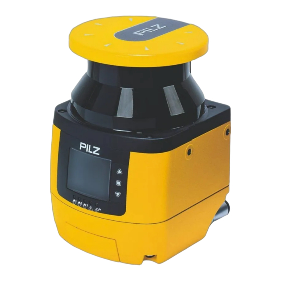
Overview Unit view Legend [1] Metal cover upper side [2] Front panel (exit laser beams) [3] Display for device messages [4] LEDs as status indicator [5] Buttons for scrolling in the display or to confirm the message in the display Scroll up Confirm message in the display Scroll down... - Page 11 Overview Legend Status of the OSSD 1/2 Lights up green: No object detected in safety zone Lights up red: Object detected in safety zone Not used Status of the warning zone 2 off: No object detected in warning zone 2 Lights up yellow: Object detected in warning zone 2 Status of the warning zone 1 off: No object detected in warning zone 1 Lights up yellow: Object detected in warning zone 1...
-
Page 12: Safety
Safety Safety Intended use The safety laser scanners of the PSEN sc M 3/5 series are electrosensitive protective equipment of ESPE type 3. They are used to protect personnel and systems. The safety laser scanners are designed to safeguard danger zones within buildings, safeguard danger zones of vehicles and access protection within buildings. -
Page 13: Safety Regulations
Safety Foreseeable misuse The safety laser scanner may not be accessed and may not be used as a step. The PSEN sc bracket H mounted on the safety laser scanner may not be accessed and not be used as a step The safety laser scanner may not be used at an ambient temperature below 0°. -
Page 14: Disposal
Safety 3.2.4 Disposal In safety-related applications, please comply with the mission time T in the safety-related characteristic data. When decommissioning, please comply with local regulations regarding the disposal of electronic devices (e.g. Electrical and Electronic Equipment Act). For your safety INFORMATION Laser radiation of the safety laser scanner The safety laser scanner of the PSEN sc M 3/5 series corresponds to the... -
Page 15: Function Description
Function description Function description Basic function of the safety laser scanner 4.1.1 Single connection The safety laser scanner monitors an area that is covered by the light beam emitted by the safety laser scanner. Fig.: Operating principle safety laser scanner Legend [1] Danger zone [2] Area covered by the laser beam... -
Page 16: Series Connection
Function description 4.1.2 Series connection In a series connection, each of the connected safety laser scanners monitors the area that is covered by the light beam emitted from the safety laser scanner. Fig.: Operating principle safety laser scanner with series connection Legend [1] Danger zone [2] Area covered by the laser beam... -
Page 17: Use Of Zone Sets And Monitoring Cases
Function description Use of zone sets and monitoring cases A safety zone and one or two warning zone(s) constitute a zone set. A monitoring case is a defined signal at the control inputs for the current machine state. For one specific machine state, one specific monitoring case can be assigned. The safety laser scanner uses the defined signal at the control inputs to activate the zone set, which is assigned to this monitoring case and therefore to a specific machine state. -
Page 18: Manual Restart
Function description Manual restart OSSD Free Locking status Interrupted Free Safety zone Not free Operated Start button Not operated Fig.: Timing diagram for manual restart Legend Operate the start button for 0.5 s to 5 s to trigger a manual restart OSSD The switched-on OSSD outputs are permanently checked by monitored test pulses. -
Page 19: Edm
Function description OSSD Fig.: Timing diagram reset Contactors outside the safety laser scanner can be monitored (External Device Monitoring = EDM, also known as feedback loop monitoring). EDM only needs to be activated if the contactors are controlled directly. A test is performed to see that the N/C contacts switch if the state of the OSSDs changes and so is used to monitor and detect malfunctions on the contactors. -
Page 20: Series Connection
Function description OSSD 24 V Fig.: Timing diagram for EDM Legend After the OSSD outputs are switched on, the EDM circuit must open within 350 ms After the OSSD outputs are switched off, the EDM circuit must close within 100 ms Use control elements whose dynamics match the times stated at t and t The function is activated or deactivated with the... -
Page 21: Wave
Function description Evaluation device PSEN sc 3/5 M b/e PSEN sc 3/5 S PSENscan Configurator Wave With the wave function, a safety laser scanner that is to be configured in a network can be identified more easily from its position. When starting the automatic search for a safety laser scanner in a network the wave button can be selected. - Page 22 Function description The muting sensors are connected to muting inputs 1 and 2. The muting sensors must be positioned and installed at a right angle to the safety laser scanner (see Installation and wiring [ 57]). When the muting state of the safety laser scanner is detected, the safety laser scanner triggers the configured actions for the muting state (e.g.
-
Page 23: Override
Function description The muting lamp must be connected to the PSEN sc M 3/5 series and positioned so that the muting lamp is clearly visible form the whole danger zone. Use a muting lamp with an LED lamp and a max. current consumption of 250 mA. If the muting lamp is defective, the muting function cannot be activated. -
Page 24: Multiple Evaluation
Function description Legend [1] Danger zone [2] Configured zone 1, monitoring not activated [3] Configured zone 2, monitoring not activated 4.13 Multiple evaluation When multiple evaluation is active, an object has to be scanned several times consecut- ively before the safety laser scanner switches the OSSDs to the OFF state. This reduces the probability that insects, welding sparks or other particles lead to a shutdown of a plant. -
Page 25: Restore Configuration
Function description National and international standards recommend reference outlines for vertical applications to reliably detect changes in the installation position of the safety laser scanners. This may be changes due to vibration or changes due to manipulation of the safety laser scanner. Fig.: Using of a reference outline on a passage Legend Danger zone... -
Page 26: Examples Of Application
Function description 4.16 Examples of application If a violation of the protective zone is detected, the evaluation device switches off the out- puts configured for this. The machine is brought to a safe condition via the connected OSSDs. If a violation of the warning zone is detected, the actions configured in PSENscan Configur- ator are performed. -
Page 27: Vertical Application
Function description 4.16.2 Vertical application Fig.: Application example PSENscan safety laser scanner - vertical configuration Legend [1] Protective zone 4.16.3 Mobile application Fig.: Application example PSENscan safety laser scanner - mobile configuration Legend [1] Warning zone 1 [2] Warning zone 2 [3] Protective zone The safety laser scanner scans the area in front of an automated guided vehicle system to prevent collisions. -
Page 28: Series Connection
Function description When the warning zone is violated, an alarm of the automated guided vehicle system can be triggered. The person can leave the route or remove the object from the route. When the protective zone is violated, a stop of the automated guided vehicle is triggered. 4.16.4 Series connection Fig.: Application example PSENscan safety laser scanner in series connection - master with three... -
Page 29: Project Configuration
Project configuration Project configuration Maintaining the safety distance 5.1.1 General The minimum distance from the start of the protected area by the safety laser scanner to the hazardous machine component should be such that the operator cannot reach the danger zone until the movement of the hazardous machine part has stopped. In accordance with the standard EN ISO 13855 this distance depends on the following factors:... -
Page 30: Horizontal Application With Stationary Danger Zone
Project configuration The allowance depends on the height of the scan plane, the detection capability and the ambient light 5.1.2 Horizontal application with stationary danger zone A horizontal application has been achieved when the safety laser scanner is aligned at an angle of max. - Page 31 Project configuration The following applies for these applications: S = K * (t ) + Z Minimum distance in mm, measured from the start of the protective zone to the danger source Approach speed with which the object to be detected is nearing the danger zone in mm/s K = 1600 mm/s when S >...
-
Page 32: Horizontal Application With Automated Guided Vehicle Systems
Project configuration Legend [1] Opening between the origin of the laser beam of the safety laser scanner and the mounting area [2] Scanning plane [3] Height H between scanning plane and base area CAUTION! Risk of injury due to insufficient safeguard Reaching into the opening between safety laser scanner and mounting area can lead to injuries. - Page 33 Please note: Height of the scan plane Pilz recommends a scan plane height of 15 cm. A person lying on the floor is detected. A lower height would lead to reduced availability because of the increased dust formation on the floor.
-
Page 34: Vertical Application
Project configuration 5.1.4 Vertical application A vertical application is given if the safety laser scanner is aligned at an angle of min. 30° with the floor level. Fig.: Schematic representation of a vertical application on a passage Legend [1] Danger zone [2] Area covered by the laser beam [3] Safety laser scanner The following applies for these applications:... -
Page 35: Calculation Of The Overall Response Time
Project configuration Additional distance depend on the detection capability d C = 8(d-14 mm) with d ≤ 40 mm C = 850 mm/s with d > 40 mm Allowance when installing near intense light sources or reflective surfaces (see Dis- tance to intense light sources and to reflective surfaces [ 37]) Calculation of the overall response time... -
Page 36: Installation Of Several Adjacent Safety Laser Scanners
Project configuration Legend [1] Area with limited detection capability Installation of several adjacent safety laser scanners When safety laser scanners have to be installed in an area, it must be ensured that an in- terference between the safety laser scanners occur at a maximum for the duration of the double rotation time (see Technical details [ 91]). -
Page 37: Ambient Conditions
Distance to intense light sources and to reflective surfaces Minimum distance to especially intense or flashing light sources Pilz recommends that the safety laser scanner is not installed near particularly intense or flashing light sources. When especially intense or flashing light sources are near the safety laser scanner (area of +/- 5°... - Page 38 Objects that may be influenced by safety laser scanners through ambient light, must not be placed within the opening angle of the laser beam. Pilz recommends that you install the safety laser scanner at a minimum distance of 2.5 m to reflective surfaces. (The recommendation was determined with a background reflection of 300 ...
- Page 39 Project configuration Allowance Z in mm Safety distance (K*T)+C+Z 5 5,5 without Z in m Fig.: Allowance with a detection capability of 70 mm Legend [1] Low level [2] Medium level [3] High level Operating Manual PSEN sc M 3/5 series | 39 1005055-EN-02...
-
Page 40: Distance From Walls
Project configuration Allowance Z in mm Safety distance (K*T)+C+Z without Z in m Fig.: Allowance with a detection capability of 40 mm Legend [1] Low level [2] Medium level [3] High level INFORMATION Determining of the allowance when the safety laser scanner has to be installed near particularly intense or flashing light sources and a re- flective background. -
Page 41: Planning Of Safety And Warning Zones And Zone Sets
Project configuration INFORMATION Used value of the teach-in function for the distance to the walls The PSENscan Configurator teach-in function uses a value of 100 mm. Planning of safety and warning zones and zone sets Specify the location and the size of the safety zone and the warning zone in accordance with the safety assessment. -
Page 42: Dust Filtration
Project configuration Legend Switchover time without advance Advance of the switchover time by the input delay Advance of the switchover time when using inputs of another device Advance of the switchover time when using inputs of external OSSDs [1] Monitoring zone set 1 is active [2] Monitoring zone set 2 is active 5.12 Dust filtration... -
Page 43: Muting
Project configuration WARNING! Loss of safety function due to a safety distance that is too low Depending on the application, serious injury or death may result. Depending on the degree of dust filtering, it is necessary to consider an allowance for calculating the safety distance when installing the safety laser scanner near intense light sources or reflective surfaces into ac- count (see Distance to intense light sources and to reflective... -
Page 44: Muting In One Direction
Project configuration The muting state occurs, – when a sensor and the second sensor detect a conveyed material simultaneously or – When a sensor has detected a conveyed material and the second sensor also detects it max. 4 s afterwards. A muting activation is not possible when the safety laser scanner is in a safe condition (LED lights up red, object detected in safety zone). -
Page 45: Muting In Two Directions
Project configuration 5.13.3 Muting in two directions Sequence for T-muting cycle when material passes from the right-hand side Legend [1] Conveyed material on conveyor [2] First muting sensor on the input side [3] Second muting sensor on the input side [4] PSEN sc M 3/5 series [5] Muting lamp [6] First muting sensor on the output side... -
Page 46: Dynamic Muting
Project configuration 5.13.4 Dynamic muting When Activate muting is selected for one of the inputs 3, 9, 10 or 11, muting can be activ- ated and deactivated dynamically. Conditions for the occurrence of muting – One of the inputs 3, 9, 10 or 11 is connected to a controller and it receives a high sig- nal from there when muting is to be activated –... - Page 47 Project configuration Condition Override 24 V Override 2 24 V Override 1 Status Override t < 400 ms Fig.: Timing diagram for override function edge-triggered Condition Override 24 V Override 2 24 V Override 1 Status Override t < 400 ms t <...
-
Page 48: Wiring
EN 60204-1. The protection type (see Technical details [ 91]) can only be achieved by using the Pilz connection leads available as an accessory. Connection to evaluation devices – Use the cables listed in the order reference (see Order references for... - Page 49 Wiring Legend [1] M12 8-pin male connector for connection to an evaluation device and the supply voltage [2] M12 12-pin male connector for connection to an evaluation device and the supply voltage [3] M12 4-pin female connector, hinged, for connection with a configuration PC [4] M12 8-pin female connector, hinged, for connection with a slave unit M12 8-pin male connector for connection to an evaluation device and the supply voltage –...
-
Page 50: Slave Unit
Wiring M12 12-pin male connector for connection to an evaluation device and the supply voltage – An OSSD pair – One configurable input – Four configurable inputs/outputs – Two inputs for supply voltage – Functional earth Pin/colour Description Brown 24 V DC Green 24 V DC Blue... -
Page 51: Configurable Inputs
Wiring 6.2.3 Configurable inputs When using the 8-pin connection, the configurable inputs at PIN 3 and 4 can be used for the following functions: Restart Reset Restart or reset Zone set switching Muting 1 and 2 Dynamic activation of the muting state When using the 12-pin connection, the configurable input at PIN 3 can be used for the fol- lowing functions: Restart... - Page 52 Wiring 2. Loosen the M3 screws of the protective cover and remove the protective cover. The screws are secured against loss and they cannot be removed. 3. Loosen the M3 screws [1] of the memory module and pull out the memory module. The screws are secured against loss and they cannot be removed.
-
Page 53: Connection To Psenscan Configurator
Wiring Legend [1] Protective membrane 5. Remove the label [1] from the memory module and insert the memory module at the safety laser scanner. 6. Fix the screw of the memory module with a torque of 1 Nm. 7. Place the protective cover at the safety laser scanner and screw the protective covers with 1 Nm. -
Page 54: Single Connection
Wiring For use in an industrial environment, Pilz recommends double-shielded twisted pair cables (S/STP). Only shielded RJ45 connectors should be used. Twisted pair cables (TP cable) consist of twisted core-pairs. Twisted pair cables are divided into categories in accordance with their electrical features (attenuation, cross-talk). Cat- egory 5 cables are specified for transferring data with Pilz Ethernet interfaces. -
Page 55: Series Connection
Wiring 6.5.2 Series connection Evaluation device PSEN sc 3/5 M b/e PSEN sc 3/5 S PSENscan Configurator Procedure: 1. Use a 4-pin cable (see Order references [ 99]) to connect the configuration PC to the safety laser scanner. 2. Use a 8-pin cable (see Order references [ 99]) to connect the master unit to the slave unit. -
Page 56: Connections For Muting Sensors
Wiring Connections for muting sensors Wire the muting sensors as shown in the following diagrams. Muting sensor Safety laser scanner 24 V Muting 1 Configurable input or input/output 24 V Configurable input or input/output Muting 2 24 V Configurable input or input/output Muting 2 24 V Configurable input or input/output... -
Page 57: Installation And Alignment
Installation and alignment Installation and alignment Installation options The safety laser scanner can be installed in various ways. Installation directly at the mounting surface [ Installation with protective bracket PSEN sc bracket H [ Installation with PSEN sc bracket PR for inclination to the side or to the top or bottom [ Installation with PSEN sc bracket P for inclination to the top and bottom [ Installation without PSEN sc bracket H... -
Page 58: Installation Of The Protective Bracket Psen Sc Bracket H At The Safety Laser Scanner
Installation and alignment Prerequisites Mounting surface with 2 through-holes for screws M5x10 mm, distance 73 mm horizont- ally towards each other for fixing the bracket of the safety laser scanner. The mounting surface has to be accessible from both sides for installation. Procedure: 1. -
Page 59: Installation With Setting Of Angle Of Inclination/Roll Angle - Bracket Psen Sc Bracket Pr
Installation and alignment Installation with setting of angle of inclination/roll angle - bracket PSEN sc bracket PR The setting of the angle of inclination of the safety laser scanner is not changed when ex- changing the safety laser scanner. Prerequisites Mounting surface with 2 drill holes, 10 mm deep, distance 73 mm horizontally towards each other for fixing the PSEN sc bracket PR or PSEN sc bracket P The protective bracket PSEN sc bracket H must already be fixed at the safety laser scan-... - Page 60 Installation and alignment Legend [1] Adjusting disc for angle of inclination [2] Set screw for the adjusting disc for angle of inclination [3] Fixing screws for safety laser scanner [4] Fine adjustment screws for the incline of the safety laser scanner 5.
-
Page 61: Installation With Angle Of Inclination Setting - Holder Psen Sc Bracket P
Installation and alignment Installation with angle of inclination setting - holder PSEN sc bracket P The setting of the angle of inclination of the safety laser scanner is not changed when ex- changing the safety laser scanner. Prerequisites Mounting surface with 2 drill holes, 10 mm deep, distance 73 mm horizontally towards each other for fixing the PSEN sc bracket PR or PSEN sc bracket P The protective bracket PSEN sc bracket H must already be fixed at the safety laser scan- ner (see... -
Page 62: Set The Angle Of Inclination Of The Safety Laser Scanner
Installation and alignment Set the angle of inclination of the safety laser scanner Procedure: 1. Change the inclination of the safety laser scanner within the permitted range of ± 6°. If necessary, loosen the fixing screws for the safety laser scanner [3], the fine adjust- ment screws for the inclination of the safety laser scanner [4] and the set screw for the adjusting disc for angle of inclination [2]. -
Page 63: Measures To Safeguard Unsecured Areas
Installation and alignment Measures to safeguard unsecured areas When installing the PSEN sc M 3/5 series areas may result that are not detected by the safety laser scanner. If required, install additional protective devices to safeguard the danger zone. Prevent stepping behind Legend [1] Danger zone with fence [2] Safeguarded area... - Page 64 Installation and alignment Prevent creeping underneath Legend [1] Mounting surface [2] Scanning plane [3] Base area [4] Safeguard area against creeping underneath [5] Edge at the mounting surface Operating Manual PSEN sc M 3/5 series | 64 1005055-EN-02...
-
Page 65: Psenscan Configurator
Install PSENscan Configurator Procedure: 1. Switch on your computer and start up the operating system. 2. Download the software PSENscan Configurator from the download area on the Pilz homepage under http://www.pilz.com/support/downloads/. 3. Double-click on the unpacked file. The software PSENscan Configurator is installed. -
Page 66: Ethernet Connections
PSENscan Configurator INFORMATION To ensure that PSENscan Configurator functions correctly, the files and dir- ectories in the installation directory of PSENscan Configurator must not be modified manually once installed (e.g. with the Windows Explorer or a text editor). 8.2.3 Ethernet Connections 8.2.3.1 Factory default settings for the IP addresses The factory-set default of the IP address of the safety laser scanner: 192.168.0.10. -
Page 67: Download Configuration To Device
PSENscan Configurator The safety laser scanner is displayed in the work window with IP address, firmware ver- sion and status information. In a safety laser scanner with a connected slave unit or several slave units all the safety laser scanners are displayed as an arrangement. 3. -
Page 68: Create Backup Copy Of A Configuration
PSENscan Configurator Create backup copy of a configuration For restoring an existing configuration (see Restore configuration [ 83]) you need a backup copy of this configuration. Procedure: Select Project -> Save. The dialogue box for saving is opened. Please enter a name for the MIB file. The MIB file includes all the data for configuration. -
Page 69: First Commissioning
Fig.: Dual-channel connection of the safety laser scanner on the input circuit of an evaluation device (1 zone set, warning message, automatic restart) Suitable Pilz evaluation devices are, for example: PNOZmulti for monitoring safety laser scanners Configure the safety laser scanner in PNOZmulti Configurator as a function element "Light curtain"... -
Page 70: Configuration Of Zones
First commissioning Automation system PSS 4000 The correct connection to the respective evaluation device is described in the operating manual for the evaluation device. Connect the evaluation device according to the specifica- tions in the selected evaluation device’s operating manual. Configuration of zones For simultaneous monitoring of several zones and the switching of monitoring of zone sets, the configurable inputs of the safety laser scanner must be configured appropriately. - Page 71 First commissioning Select Muting = Activated The outputs Pin 5 and 6 are reserved for OSSD 1 and OSSD 2 and cannot be changed. Click on the arrow . The next window Configure zone sets is opened. 5. Click on the arrow .
-
Page 72: Example For An 12-Pin Connection
First commissioning WARNING! Loss of safety function due to a safety distance that is too low Depending on the application, serious injury or death may result. Depending on the degree of dust filtering, it is necessary to consider an allowance for calculating the safety distance when installing the safety laser scanner near intense light sources or reflective surfaces into ac- count (see Distance to intense light sources and to reflective... - Page 73 First commissioning Device You can enter a title for the connected device under Name. Safety laser scanner arrangement You can enter a title for the safety laser scanner arrangement under Name. You can enter names for the devices in the safety laser scanner arrangement under Device.
- Page 74 First commissioning 6. For Restart select the value Automatic and define the Recovery time (min. 200 ms, max. 60000 ms). Select whether EDM is to be activated. When EDM is activated, a PIN must be as- signed to the EDM input. 7. Click on the arrow .
-
Page 75: Testing
First commissioning 12. Click on Specify at least 3 (max. 15) reference points. Specify a max. permitted tolerance for each reference point. Tol - is the tolerance for the side that faces the safety laser scan- ner, Tol + is the tolerance for the side that is facing away from the safety laser scanner. 13. - Page 76 First commissioning It must not be possible to operate the pushbutton for manual restart from inside the danger zone. The pushbutton must be located at a position from which there is a full, un- obstructed view of the danger zone. Response time and stopping time must fulfil the requirements in Maintaining the safety distance [...
-
Page 77: Operation
Operation Operation 10.1 Display during normal operation Message in the display Status Description/measure Icon Text CLEANW2 The front panel must be cleaned Decommission the safety laser scan- ner and clean [ the front panel of the safety laser scanner. DLDNC Download of a configuration or a re- A configuration or a report is down- port... -
Page 78: Display Of The Monitoring Status
Operation Message in the display Status Description/measure Icon Text OVERRIDE Override is active. Override has elapsed. TIMEOUT 10.2 Display of the monitoring status Icon Status Description/measure Valid config- Configura- uration tion not yet accepted Device is switched on and ready for operation Warning zone has been violated A violation of the warning zone has... -
Page 79: Diagnostic Information
An error occurred during the system Perform a reset of the safety laser test. scanner [ 85]. If the error persists, please contact Pilz. INTF2 An error occurred during the system Perform a reset of the safety laser test. scanner [ 85]. - Page 80 An error occurred during the system Perform a reset of the safety laser test. scanner [ 85]. If the error persists, please contact Pilz. INTF9 An error occurred during the system Perform a reset of the safety laser test. scanner [ 85].
-
Page 81: Warnings
An error occurred during the system Perform a reset of the safety laser test. scanner [ 85]. If the error persists, please contact Pilz. INTF20 An error occurred during the system Perform a reset of the safety laser test. scanner [ 85]. -
Page 82: Information
Operation 10.3.3 Information Message in the display Error/cause Description/measure Icon Text CLEANW2 The font panel of the safety laser Clean front panel scanner is contaminated and it must be cleaned to ensure normal opera- tion. DLDNC A new configuration is downloaded. DLDNF A new firmware version is down- loaded. -
Page 83: Restore Configuration
Operation Menu item Menu second Meaning level Serial number The serial number of PSEN sc M 3/5 series is dis- played. Firmware version The firmware version of PSEN sc M 3/5 series is displayed. Device Lifetime (h) The current operating time of PSEN sc M 3/5 series in hours is displayed Configuration Configuration-specific displays... - Page 84 Operation The system checks whether the conditions are met. When the conditions are met, restoring of the configuration is started. 2. Depending on the type of difference between memory module and PSEN sc M the restoring of the configuration varies. Serial numbers differ: On the display of the master unit, CFG NO MATCHING is shown. Continue by selecting the data for the restore.
-
Page 85: Reset
Operation 10.6 Reset The Reset function can be used to set the safety laser scanner back to normal operation, when the safety laser scanner has changed to an error state because of a non-critical error. Procedure: Hold the reset pushbutton down for at least 500 ms. Operating Manual PSEN sc M 3/5 series | 85 1005055-EN-02... -
Page 86: Safety Checks, Maintenance And Repair
Improper cleaning agents can damage the front screen and lead to malfunc- tions. – Use only the cleaning agents specified. A scratched front panel can lead to errors of the safety laser scanner. Contact Pilz and exchange the PSEN sc head when the front panel is scratched. Contamination Cleaning Finger marks Dampen PSEN sc cloth with a mild cleaning agent or PSEN sc cleaner (see... -
Page 87: Checks
Regular checks can bring to light changes to the plant/machine, safeguards and ambient conditions. Pilz recommends that the safety laser scanner be checked every six months. Check the safety laser scanner’s front panel. – Scratched front panel: Change the safety laser scanner. -
Page 88: Dimensions
Dimensions Dimensions Master unit 59.5 112.5 M5x8 (4x) Side view Plan view Rear view View from below with protective cover Operating Manual PSEN sc M 3/5 series | 88 1005055-EN-02... - Page 89 Dimensions Slave unit 59.5 112.5 M5x8(4x) Side view Plan view Rear view View from below with protective cover Operating Manual PSEN sc M 3/5 series | 89 1005055-EN-02...
- Page 90 Dimensions PSEN sc bracket PR Front view Side view Operating Manual PSEN sc M 3/5 series | 90 1005055-EN-02...
-
Page 91: Technical Details Order No. 6D000016-6D000017
Technical details order no. 6D000016-6D000017 Technical details order no. 6D000016-6D000017 General 6D000016 6D000017 Certifications CE, TÜV, cULus Listed CE, TÜV, cULus Listed ESPE type Product type Master Master Sensor's mode of operation Optical Optical Resolutions 40 mm, 70 mm 40 mm, 70 mm Number of zone sets that can be switched Operating range... - Page 92 Technical details order no. 6D000016-6D000017 Configurable inputs/outputs (in- 6D000016 6D000017 puts or auxiliary outputs) Number Inputs 6D000016 6D000017 Number Signal level at "0" < 5 V < 5 V Signal level at "1" > 12 V > 12 V Voltage at inputs 24 V 24 V Current per input...
- Page 93 Technical details order no. 6D000016-6D000017 Environmental data 6D000016 6D000017 Shock stress In accordance with the standard EN 60068-2-27 EN 60068-2-27 Number of shocks 1000 1000 Acceleration Duration 16 ms 16 ms Protection type Housing IP65 IP65 Deviation from ideal flatness of the scan field at max.
-
Page 94: Technical Details Order No. 6D000020-6D000021
Technical details order no. 6D000020-6D000021 Technical details order no. 6D000020-6D000021 General 6D000020 6D000021 Certifications CE, TÜV, cULus Listed CE, TÜV, cULus Listed ESPE type Product type Slave Slave Sensor's mode of operation Optical Optical Resolutions 40 mm, 70 mm 40 mm, 70 mm Number of zone sets that can be switched Operating range... - Page 95 Technical details order no. 6D000020-6D000021 Configurable inputs/outputs (in- 6D000020 6D000021 puts or auxiliary outputs) Number Inputs 6D000020 6D000021 Number Signal level at "0" < 5 V < 5 V Signal level at "1" > 12 V > 12 V Voltage at inputs 24 V 24 V Current per input...
- Page 96 Technical details order no. 6D000020-6D000021 Environmental data 6D000020 6D000021 Shock stress In accordance with the standard EN 60068-2-27 EN 60068-2-27 Number of shocks 1000 1000 Acceleration Duration 16 ms 16 ms Protection type Housing IP65 IP65 Deviation from ideal flatness of the scan field at max.
-
Page 97: Safety Characteristic Data
Safety characteristic data Safety characteristic data NOTICE You must comply with the safety characteristic data in order to achieve the required safety level for your plant/machine. Operating EN ISO EN ISO EN 62061 EN 62061 IEC 61511 IEC 61511 EN ISO mode 13849-1: 13849-1: 13849-1:... -
Page 98: Network Data
Network data Network data Interface Protocol Direction Transport Port No. Can be de- Description activated User interface proprietary 2000 Monitoring User interface proprietary in/out 3000 Receive command User interface proprietary in/out 4088 Find device in network User interface proprietary in/out 12000 Poll configur- ation data... -
Page 99: Order Reference
Order reference Order reference 17.1 System Product type Features Order no. PSEN sc M 3.0 Safety laser scanner, range 3 m, master unit, M12, 8/12‑pin 6D000016 08-12 PSEN sc M 5.5 Safety laser scanner, range 5.5 m, master unit, M12, 8/12‑pin 6D000017 08-12 PSEN sc S 3.0 Safety laser scanner, range 3 m, slave unit 6D000020... - Page 100 Order reference Product type Features Connector X1 Connector X2 Connector X3 Order no. PSEN cable M12, 12-pin fe- 570 350 M12-12sf 2m male con- nector, straight PSEN cable M12, 12-pin fe- 570 351 M12-12sf 3m male con- nector, straight PSEN cable M12, 12-pin fe- 570 352 M12-12sf 5m...
-
Page 101: Appendix
Appendix Appendix 18.1 Check list The check list below is intended as an aid in for the following work on a safety laser scan- ner of the PSEN sc M 3/5 series: During commissioning, recommissioning, and running the specified regular check. Note that the check list is not intended to replace the plant-specific safety analysis required for commissioning/recommissioning, nor the resulting inspections and actions. - Page 102 Appendix Action Not OK Notes Check minimum distance to danger zone Has the minimum distance been calcu- lated in accordance with the applicable standards? Has the calculated minimum distance been maintained at all points? Check safety zone Has the ability to creep underneath the safety zone undetected been ex- cluded? Check safety laser scanner...
- Page 103 Appendix Action Not OK Notes Check the protective function of the safety laser scanner Violate the safety zone at various points: The hazardous movement must be shut down. Switch off the safety laser scanner Is the hazardous movement stopped immediately when you switch off? Operating Manual PSEN sc M 3/5 series | 103 1005055-EN-02...
- Page 104 Identification Identification The safety laser scanner's year and month of manufacture is encoded within its serial num- ber. The serial number is a 9-digit code. X YY M ##### Legend X Internal designation (any letter) YY Year of manufacture 16 = 2016 17 = 2017 18 = 2018 19 = 2019...
- Page 105 European Parliament and of the Council. The complete EC Declaration of Conformity is available on the Internet at www.pilz.com/downloads. Authorised representative: Norbert Fröhlich, Pilz GmbH & Co. KG, Felix-Wankel-Str. 2, 73760 Ostfildern, Germany Operating Manual PSEN sc M 3/5 series...
- Page 106 We are represented internationally. Please refer to our homepage www.pilz.com for further details or contact our headquarters. Headquarters: Pilz GmbH & Co. KG, Felix-Wankel-Straße 2, 73760 Ostfildern, Germany Telephone: +49 711 3409-0, Telefax: +49 711 3409-133, E-Mail: info@pilz.com, Internet: www.pilz.com...
Need help?
Do you have a question about the PSEN sc M 3 Series and is the answer not in the manual?
Questions and answers