Pilz PSEN sc L 3.0 08-12 Operating Manual
Hide thumbs
Also See for PSEN sc L 3.0 08-12:
- Operating manual (135 pages) ,
- Operating manual (106 pages) ,
- Operating manual (121 pages)
Table of Contents
Advertisement
Quick Links
Advertisement
Table of Contents

Related Manuals for Pilz PSEN sc L 3.0 08-12


Summary of Contents for Pilz PSEN sc L 3.0 08-12
- Page 1 PSEN sc L 3.0/5.5 08-12 PSEN sensor technology Operating Manual-1005056-EN-04...
- Page 2 Preface This document is the original document. All rights to this documentation are reserved by Pilz GmbH & Co. KG. Copies may be made for the user's internal purposes. Suggestions and comments for improving this documenta- tion will be gratefully received.
-
Page 3: Table Of Contents
Contents Introduction ..........................Validity of documentation......................Using the documentation ......................Definition of symbols......................... Overview ..........................Device features ......................... Device view..........................Safety ............................Intended use ..........................Safety regulations ........................3.2.1 Safety assessment ........................3.2.2 Use of qualified personnel ......................3.2.3 Warranty and liability ........................ - Page 4 Contents 6.2.1 General ............................. 6.2.2 Horizontal application with stationary danger zone ..............6.2.3 Horizontal application with automated guided vehicle systems..........6.2.4 Vertical application........................6.2.4.1 Detect body parts........................37 Calculation of the overall response time................... Switching of zone sets ......................Monitoring of reference outlines ....................
- Page 5 Contents Installation..........................9.2.1 System requirements ........................ 9.2.2 Install PSENscan Configurator ....................9.2.3 Ethernet Connections ....................... 9.2.3.1 Factory default settings for the IP addresses ................77 9.2.3.2 Create firewall rule ........................77 9.2.3.3 Connect automatically ......................77 Download configuration to device..................... Create backup copy of a configuration ..................
- Page 6 Contents Dimensions ..........................Technical details order no. 6D000012-6D000013 ..............Safety characteristic data ..................... Network data .......................... Order reference ........................17.1 System ............................17.2 Accessories ..........................Appendix ..........................18.1 Check list ..........................Identification .......................... EC declaration of conformity ....................Operating Manual PSEN sc L 3.0/5.5 08-12 1005056-EN-04...
-
Page 7: Introduction
This documentation is valid for the following products from version 1.0. It is valid until new documentation is published. Product type Designation in this operating manual PSEN sc L 3.0 08-12 PSEN sc L PSEN sc L 5.5 08-12 This operating manual explains the function and operation, describes the installation and provides guidelines on how to connect the product. - Page 8 Introduction NOTICE This describes a situation in which the product or devices could be dam- aged and also provides information on preventive measures that can be taken. It also highlights areas within the text that are of particular import- ance. INFORMATION This gives advice on applications and provides information on special fea- tures.
-
Page 9: Overview
Overview Overview Device features Safety laser scanners of the PSEN sc L 3.0/5.5 08-12 series constitute electrosensitive pro- tective equipment (ESPE type: 3) in accordance with EN 61496-3 for workspaces in which machines, robots, and automated systems might pose a physical danger to their operators. Creating the configuration with PSENscan Configurator –... -
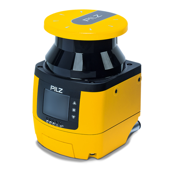
Page 10: Device View
Overview Device view Legend [1] Metal cover upper side [2] Front panel (exit laser beams) [3] Display for device messages [4] LEDs as status indicator [5] Buttons for scrolling in the display or to confirm the message in the display Scroll up Confirm message in the display Scroll down... - Page 11 Overview Legend State OSSD 11/12 State OSSD 21/22 Warning zone 2 Status warning zone 1 Status interlock Detailed description of the LEDs: Icon State Meaning = LED on = LED off OSSD 11/12 No object detected in safety zone 1 Green Object detected in safety zone 1...
- Page 12 Overview Icon State Meaning = LED on = LED off Warning zone 1 No object detected in warning zone 1 Object detected in warn- ing zone 1 Yellow Locking No object detected in yellow and safety zone, lights up red PSEN sc L 3.0/5.5 08-12 series waits for manual restart...
-
Page 13: Safety
Safety Safety Intended use The safety laser scanners of the PSEN sc L 3.0/5.5 08-12 series are electrosensitive pro- tective equipment of ESPE type 3. They are used to protect personnel and systems. The safety laser scanners are designed to safeguard the danger zone, secure hazardous areas of vehicles and protect the access within buildings. -
Page 14: Safety Regulations
Safety Foreseeable misuse The safety laser scanner may not be accessed and may not be used as a step. The PSEN sc bracket H mounted on the safety laser scanner may not be accessed and not be used as a step Safety regulations 3.2.1 Safety assessment... -
Page 15: For Your Safety
Safety For your safety INFORMATION Laser radiation of the safety laser scanner The safety laser scanner of the PSEN sc L 3.0/5.5 08-12 series corres- ponds to the laser class 1 in accordance with EN 60825-1. Additional meas- ures to shield the laser beams are not required (eye-safe). Operating Manual PSEN sc L 3.0/5.5 08-12 | 15 1005056-EN-04... -
Page 16: Security
Perform a risk assessment in accordance with VDI/VDE 2182 or IEC 62443-3-2 and plan the security measures with care. If necessary, seek advice from Pilz Customer Support. Required security measures The product is not protected from physical manipulation or from reading of memory con- tents during physical access. - Page 17 – Make the users aware of the responsible use of their access data. Assign different permissions for the various user groups (e.g. diagnostics - configuration). As soon as possible, install firmware updates that Pilz provides for the product. Before disposal, the product must be safely decommissioned. To do this, all the data must be deleted from the device.
-
Page 18: Function Description
Function description Function description Basic function of the safety laser scanner The safety laser scanner monitors an area that is covered by the light beam emitted by the safety laser scanner. Fig.: Operating principle safety laser scanner Legend [1] Danger zone [2] Area covered by the laser beam [3] Safety laser scanner [4] Safety zone... -
Page 19: Stationary And Mobile Danger Zone
Function description Stationary and mobile danger zone Using the safety laser scanner, you can monitor a stationary or mobile danger zone, e.g. the environment of a machine that is installed in a fixed position or an area in front of an automated guided vehicle. -
Page 20: Horizontal Application
Function description 5.2.1 Horizontal application Fig.: Application example PSENscan safety laser scanner - horizontal configuration Legend [1] Warning zone [2] Safety zone 5.2.2 Vertical application Fig.: Application example PSENscan safety laser scanner - vertical configuration Legend [1] Safety zone Operating Manual PSEN sc L 3.0/5.5 08-12 | 20 1005056-EN-04... -
Page 21: Mobile Application
Function description 5.2.3 Mobile application Fig.: Application example PSENscan safety laser scanner - mobile configuration Legend [1] Warning zone 1 [2] Warning zone 2 [3] Safety zone The safety laser scanner scans the area in front of an automated guided vehicle system to prevent collisions. -
Page 22: Automatic And Monitored Start/Restart
Function description Therefore, a change of signals at the control inputs triggers a change of the active zone set. When a machine has different operating statuses, a safety laser scanner can be used to monitor several operating statuses. When using several zone sets, the monitoring of a zone set can be switched to the monitor- ing of the next zone set. -
Page 23: Manual Restart
Function description Manual restart OSSD Free Safety zone Not free Operated Start button Not operated Fig.: Timing diagram for manual restart Legend Start pushbutton pressed for < 0.5 s, no manual reset triggered Start pushbutton pressed 0.5 s to 5 s, manual restart is triggered With the manual restart it is not possible to bring a safety laser scanner to normal operation when it was in an error state, and whose error is rectified. -
Page 24: Coding Against Interference
Function description The automatic reset function is permanently deactivated when the PSEN sc L 3.0/5.5 08-12 series switches to an error state more than 5 times within 15 minutes with an INTFx error. The PSEN sc L 3.0/5.5 08-12 series must be switched off and then on again. Coding against interference Safety laser scanners that can influence each other can be operated in the same room when beam coding of the safety laser scanner is set up. -
Page 25: Wave
Function description OSSD 24 V Fig.: Timing diagram for EDM Legend After the OSSD has changed to the ON state, the EDM circuit must open within 350 ms After the OSSD has changed to the OFF state, the EDM circuit must close within 100 ms Use control elements whose dynamics match the times stated at t and t... -
Page 26: Muting
Function description 5.14 Muting The muting function can be used to suspend the safety function of the safety laser scanner during operation, subject to special operating conditions. Example of a special operating condition: Material is transported into the safety zone on a conveyor and the safety function is over- ridden for the time it takes the material to pass through. -
Page 27: Override
Function description Legend [1] Safety zone [2] Muting zone [3] Transported material [4] Safety laser scanner 5.15 Override With the override function, a machine can be restarted even though the safety zone is viol- ated by material. The aim is to clear the danger zone of any material that may have accumulated due to a fault in the operating cycle. -
Page 28: Multiple Evaluation
Function description Automatic ending of override function The override function is ended automatically when one of the following conditions is met: Muting timeout has elapsed The conditions necessary for activation are no longer present. Max. duration of override function has elapsed: After 120 s, the safety laser scanner switches back to its normal operating state. -
Page 29: Protection Against Manipulation
Function description 5.19 Protection against manipulation The safety laser scanner permanently monitors the environment to detect manipulations in the workspace or on the safety laser scanner. Possible consequences of manipulations: Loss of the safety function, Reduced performance, Operational malfunctions. If a manipulation indication is detected, the OSSDs switch to the OFF state. The display of the safety laser scanner shows Indicator for a manipulation: With at least 700 consecutive light beams of the safety laser scanner, no sufficiently... -
Page 30: Project Configuration
Project configuration Project configuration General The minimum distance from the start of the protected area by the safety laser scanner to the dangerous machine component should be such that the operator cannot reach the danger zone until the movement of the dangerous machine part has stopped. Influencing factors in accordance with EN ISO 13855 Overall response time of the safety laser scanner Time between the response of the safety laser beam to an event and the change of the... -
Page 31: Maintaining The Safety Distance
Project configuration Maintaining the safety distance 6.2.1 General The minimum distance from the start of the protected area by the safety laser scanner to the dangerous machine component should be such that the operator cannot reach the danger zone until the movement of the dangerous machine part has stopped. Influencing factors in accordance with EN ISO 13855 Overall response time of the safety laser scanner Time between the response of the safety laser beam to an event and the change of the... -
Page 32: Horizontal Application With Stationary Danger Zone
Project configuration 6.2.2 Horizontal application with stationary danger zone A horizontal application has been achieved when the safety laser scanner is aligned at an angle of max. 30° with the floor level. Fig.: Schematic representation minimum distance from the start of the protected area to the danger zone Legend [1] Danger zone... - Page 33 Project configuration Approach speed with which the object to be detected is nearing the danger zone in mm/s K = 1600 mm/s when S > 500 mm K = 2000 mm/s when S ≤ 500 mm Overall response time of the safety laser scanner in seconds (see Calculation of the overall response time [ 38])
-
Page 34: Horizontal Application With Automated Guided Vehicle Systems
Project configuration Legend [1] Opening between the origin of the laser beam of the safety laser scanner and the mounting area [2] Scanning plane [3] Height H between scanning plane and base area CAUTION! Risk of injury due to insufficient safeguard Reaching into the opening between safety laser scanner and mounting area can lead to injuries. - Page 35 (AGV) in mm (10 % of braking distance S Note: Height of the scan plane Pilz recommends a scan plane height of 15 cm. A person lying on the floor is detected. A lower height would lead to reduced availability because of the increased dust formation on the floor.
-
Page 36: Vertical Application
Project configuration CAUTION! Risk of injury due to insufficient safeguard Reaching into the opening between safety laser scanner and mounting area can lead to injuries. – Prevent reaching into the opening by using a suitable safeguard. 6.2.4 Vertical application A vertical application is given when the safety laser scanner is aligned at an angle of over ± 30°... -
Page 37: Detect Body Parts
Project configuration Approach speed with which the object to be detected is nearing the danger zone in mm/s K = 1600 mm/s when S > 500 mm K = 2000 mm/s when S ≤ 500 mm Overall response time of the safety laser scanner in seconds (see Calculation of the overall response time [ 38]) -
Page 38: Calculation Of The Overall Response Time
In the PSENscan Configurator the automatic assignment ensures a difference in exactly two positions. Pilz recommends that the automatic assignment by the PSENscan Configurator is used. Operating Manual PSEN sc L 3.0/5.5 08-12 | 38... -
Page 39: Monitoring Of Reference Outlines
Project configuration Fig.: Example for the automatic coding of 6 zone sets by the PSENscan Configurator to ensure the differentiation to the next monitoring case (Hamming code) Monitoring of reference outlines An outline within the area covered by laser beams can be defined and monitored in PSENscan Configurator as a reference outline. - Page 40 Project configuration Monitoring of reference outlines is used to detect any changes or changes to the environ- ment of the safety laser scanner. Changes to the installation position of the safety laser scanner due to vibration Changes of the safety laser scanner due to manipulation Changes of an additional protective equipment Applications of a reference outline for protecting moveable constructions When the reference points are set to the position of a moveable construction, for example a...
- Page 41 Project configuration Applications of a reference outline for protecting additional protective equipment When the reference points are set to the positions of additional protective equipment, for example mechanical barriers, the safety laser scanner switches the OSSDs to the OFF state when one of the marked positions changes. Fig.: Using a reference outline for protecting additional protective equipment Legend Danger zone...
-
Page 42: Area With Limited Detection Capability
Project configuration Area with limited detection capability In the area of max. 100 mm before the laser scanner there is an areas with limited detec- tion capability. Note: Ensure that the area is not part of the danger zone. Install the safety laser scanner so that no objects can enter the zone with limited detec- tion capability. -
Page 43: Ambient Conditions
Project configuration Change the inclination of the safety laser scanners. Place an opaque object between the safety laser scanners Ambient conditions Information given in the Technical details [ 112] must be followed. If there is a highly reflective background within a distance of 2.5 m from the safety zone perimeter (e.g. -
Page 44: Dust Filtration
Distance to intense light sources and to reflective surfaces Minimum distance to especially intense or flashing light sources Pilz recommends that the safety laser scanner is not installed near particularly intense or flashing light sources (e.g. flash units). When especially intense or flashing light sources are near the safety laser scanner (area of +/- 5°... -
Page 45: Distance From Walls
Project configuration Minimum distance from reflective surfaces Pilz recommends that reflective surfaces with a distance of 3 m to the safety zone are re- moved. If this is not possible, the allowance Z must be considered when calculating the safety distance. -
Page 46: Planning Of Safety And Warning Zones And Zone Sets
Project configuration 6.12 Planning of safety and warning zones and zone sets Specify the location and the size of the safety zone and the warning zone in accordance with the safety assessment. Specify in what situations the switching operation of the zone sets are to take place. 6.13 Switchover time with zone selection The zone selection is performed by signals that are present at the control inputs. -
Page 47: Muting
Project configuration Legend Switchover time without advance Advance of the switchover time by the configured value of the input delay Advance of the switchover time when using inputs of another device Advance of the switchover time when using inputs of external OSSDs [1] Monitoring zone set 1 is active [2] Monitoring zone set 2 is active 6.15... - Page 48 Project configuration Muting means a temporary suspension of the safety function. For this reason, the muting function must have a time restriction. When the muting sensors are activated and the mut- ing status begins, an internal clock is started. If the muting sensors are still active after 10 minutes (status when delivered), the muting status is cancelled and the safety laser scan- ner grid switches to a safe condition.
-
Page 49: Muting In Two Directions
Project configuration A muting activation is not possible when the safety laser scanner is in a safe state (LED lights up red, object detected in safety zone). Different conveyor speeds in the area of a PSEN sc L 3.0/5.5 08-12 series should be prevented. The muting sensor A1 and the muting sensor A2 must be connected to the configurable input Muting 1. - Page 50 Project configuration Input Muting 1 Input Muting 2 Muting function Fig.: Timing diagram T muting Legend Delay between Muting 1 and Muting 2 (configurable from 1-16 s) Duration of the muting state (max. up to the configurable time exceeded) Internal delay before the ending of the muting state (max. 30 ms) Delay between Muting 1 and Muting 2 (configurable from 1-16 s) Duration of the muting state (max.
- Page 51 Project configuration Phase in the muting Explanation cycle Material has already passed the first muting sensor and is being transported on the conveyor in the direction of the second mut- ing sensor, muting lamp off. Material on the conveyor passes the second muting sensor (max. 4 s after the first sensor was passed).
-
Page 52: Muting In One Direction
Project configuration L Length of the object that triggers the muting status as it passes the muting sensors V Speed at which the object is moving Distance between the muting sensors A1 and B1, and between A2 and B2 Distance between muting sensor A1 and muting sensor A2 MutingOff L Length of the object that triggers the muting status as it passes the muting sensors... - Page 53 Project configuration Note: Use L muting only to remove material from the danger zone. Input Muting 1 Input Muting 2 Muting function Fig.: Timing diagram L muting Legend Delay between Muting 1 and Muting 2 (configurable from 1-16 s) Duration of the muting state (max. up to the configurable time exceeded) Internal delay before the ending of the muting state (max.
- Page 54 Project configuration Please note the following distances and times when installing the safety laser scanner and using the muting function: Phase in the muting Explanation cycle Material has already passed the first muting sensor and is being transported in the direction of the second muting sensor, muting lamp off.
-
Page 55: Dynamic Muting
Project configuration Icon Unit Minimum Maximum value Description value Distance between muting MutingOff sensor A1 and the position from which the muting func- tion is turned off again Distances for muting with 2 sensors 6.15.4 Dynamic muting When Activate muting is selected for an input, muting can be activated and deactivated dynamically. - Page 56 Project configuration Condition Override 24 V Override 2 24 V Override 1 Status Override t < 400 ms Fig.: Timing diagram for override function edge-triggered Condition Override 24 V Override 2 24 V Override 1 Status Override t < 400 ms t <...
-
Page 57: Rest Condition
Project configuration 6.17 Rest condition The safety laser scanner can only be switched to the rest condition, when more than one zone set is configured no safety or warning zones are configured in the relevant zone set. Settings of encoders in the relevant zone set are removed. The settings in a configuration remain saved. -
Page 58: Wiring
EN 60204-1. The protection type (see Technical details [ 112]) can only be achieved by using the Pilz connection leads available as an accessory. Connection to evaluation devices – Use the cables listed in the order reference (see Order references for accessories [ 117]) or equivalent cables. - Page 59 Wiring Legend [1] M12 8-pin male connector for connection to an evaluation device and the supply voltage [2] M12 12-pin male connector for connection to an evaluation device and the supply voltage [3] M12 4-pin female connector, hinged, for connection to a configuration PC [4] M12 8-pin socket, hinged, not used M12 8-pin male connector for connection to an evaluation device and the supply voltage –...
-
Page 60: Configurable Inputs/Outputs
Wiring M12 12-pin male connector for connection to an evaluation device and the supply voltage – An OSSD pair – One configurable input – Four configurable inputs/outputs (two inputs/outputs are possible as OSSD pair) – Two inputs for supply voltage –... -
Page 61: Configurable Inputs
Wiring When using the 12-pin connection, the configurable inputs/outputs at PIN 7, 9, 10 and 11 can be used for the following functions: Warning output Alarms 1 or 2 Muting lamp The inputs/outputs at PIN 9 and 10 can be used as OSSD pair. For PINs that you do not use as outputs, select No function. -
Page 62: Connect Supply Voltage And Safety Controller
Wiring Connect supply voltage and safety controller The supply voltage connection is in the memory module that is protected by a screwed-on cover. The memory module can be uninstalled for simpler connection. Note: The memory module must only be uninstalled when the supply voltage is switched off. Procedure: 1. - Page 63 Wiring 4. Connect the supply voltage and the safety controller to the 8-pin or the 12-pin socket on the memory module. 5. Remove the protective membrane [1] from the memory module and insert the memory module at the safety laser scanner. Legend [1] Protective membrane [2] Memory module...
-
Page 64: Connection To Psenscan Configurator
Note: Ensure that the software PSENscan Configurator is installed on the configuration PC. We recommend that you always use the latest version (download from www.pilz.com) Ensure that the safety laser scanner is switched off when creating a connection to the configuration PC. - Page 65 Wiring Evaluation device PSEN sc PSENscan Configurator Procedure: 1. Use a 4-pin cable (see Order references [ 117]) to connect the configuration PC to the safety laser scanner. 2. Connect the safety laser scanner to the supply voltage and an evaluation device [ 80].
-
Page 66: Connections For Muting Sensors
Wiring Connections for muting sensors Wire the muting sensors as shown in the following diagrams. Muting sensor Safety laser scanner 24 V Muting 1 Configurable input or input/output 24 V Muting 2 Configurable input or input/output 8-pin connection: 3, 4, 1 12-pin connection: 3, 7, 9, 10, 11 Fig.: Wiring of 2 muting sensors on PSEN sc L 3.0/5.5 08-12 series... -
Page 67: Installation And Alignment
Installation and alignment Installation and alignment Installation options The safety laser scanner can be installed in various ways. Installation directly at the mounting surface [ Installation to the floor with PSEN bracket F [ Installation with protective bracket PSEN sc bracket H [ Installation with PSEN sc bracket PR for inclination to the side or to the top or bottom [ Installation with PSEN sc bracket P for inclination to the top and bottom [... -
Page 68: Installation Of The Protective Bracket Psen Sc Bracket H At The Safety Laser Scanner
Installation and alignment Prerequisites Mounting surface with 2 through-holes for screws M5x10 mm, distance 73 mm horizont- ally towards each other for fixing the bracket of the safety laser scanner. The mounting surface has to be accessible from both sides for installation. Procedure: 1. -
Page 69: Installation On The Floor
Installation and alignment Installation on the floor Prerequisites The protective bracket PSEN sc bracket H must already be fixed at the safety laser scan- ner (see Installation of the protective bracket PSEN sc bracket H at the safety laser scanner [ 68]). Procedure: 39,5 [1] Drill holes for attachment to floor PSEN sc installed on PSEN sc bracket F... -
Page 70: Installation With Setting Of Angle Of Inclination/Roll Angle - Bracket Psen Sc Bracket Pr
Installation and alignment Installation with setting of angle of inclination/roll angle - bracket PSEN sc bracket PR The setting of the angle of inclination of the safety laser scanner is not changed when ex- changing the safety laser scanner. Prerequisites Mounting surface with 2 drill holes, 10 mm deep, distance 73 mm horizontally towards each other for fixing the PSEN sc bracket PR or PSEN sc bracket P The protective bracket PSEN sc bracket H must already be fixed at the safety laser scan-... - Page 71 Installation and alignment Legend [1] Adjusting disc for angle of inclination [2] Set screw for the adjusting disc for angle of inclination [3] Fixing screws for safety laser scanner [4] Fine adjustment screws for the incline of the safety laser scanner 5.
-
Page 72: Installation With Angle Of Inclination Setting - Holder Psen Sc Bracket P
Installation and alignment Installation with angle of inclination setting - holder PSEN sc bracket P The setting of the angle of inclination of the safety laser scanner is not changed when ex- changing the safety laser scanner. Prerequisites Mounting surface with 2 drill holes, 10 mm deep, distance 73 mm horizontally towards each other for fixing the PSEN sc bracket PR or PSEN sc bracket P The protective bracket PSEN sc bracket H must already be fixed at the safety laser scan- ner (see... -
Page 73: Set The Angle Of Inclination Of The Safety Laser Scanner
Installation and alignment Set the angle of inclination of the safety laser scanner Procedure: 1. Change the inclination of the safety laser scanner within the permitted range of ± 6°. If necessary, loosen the fixing screws for the safety laser scanner [3], the fine adjust- ment screws for the inclination of the safety laser scanner [4] and the set screw for the adjusting disc for angle of inclination [2]. -
Page 74: Measures To Safeguard Unsecured Areas
Installation and alignment Measures to safeguard unsecured areas When installing the PSEN sc L 3.0/5.5 08-12 series areas may result that are not detected by the safety laser scanner. If required, install additional protective devices to safeguard the danger zone. Prevent stepping behind Legend [1] Danger zone with fence... - Page 75 Installation and alignment Prevent creeping underneath Legend [1] Mounting surface [2] Scanning plane [3] Base area [4] Safeguard area against creeping underneath [5] Edge at the mounting surface Operating Manual PSEN sc L 3.0/5.5 08-12 | 75 1005056-EN-04...
-
Page 76: Psenscan Configurator
Install PSENscan Configurator Procedure: 1. Switch on your computer and start up the operating system. 2. Download the software PSENscan Configurator from the download area on the Pilz homepage under http://www.pilz.com/support/downloads/. 3. Double-click on the unpacked file. The software PSENscan Configurator is installed. -
Page 77: Ethernet Connections
PSENscan Configurator INFORMATION To ensure that PSENscan Configurator functions correctly, the files and dir- ectories in the installation directory of PSENscan Configurator must not be modified manually once installed (e.g. with the Windows Explorer or a text editor). 9.2.3 Ethernet Connections 9.2.3.1 Factory default settings for the IP addresses The factory-set default of the IP address of the safety laser scanner: 192.168.0.10. -
Page 78: Download Configuration To Device
PSENscan Configurator 2. Double-click the safety laser scanner from Network environment. The safety laser scanner is displayed in the work window with IP address, firmware ver- sion and status information. In a safety laser scanner with a connected slave unit or several slave units all the safety laser scanners are displayed as an arrangement. -
Page 79: Create Backup Copy Of A Configuration
Take down the counter shown and the serial number of the safety laser scanner. Do not close the window unless you have a new password. 2. For resetting the password, please contact Pilz. Name the counter shown and the serial number of the safety laser scanner. -
Page 80: First Commissioning
First commissioning First commissioning 10.1 Requirements for commissioning Note: Ensure that the window of the safety laser scanner is clean, intact and without finger- prints. CAUTION! Detection of safety zones being violated deteriorates If the safety laser scanner is commissioned in deviating conditions, the de- tection of the safety zones being violated may deteriorate. -
Page 81: Configuration Of Zones
Fig.: Dual-channel connection of the safety laser scanner with 12-pin male connector on the input cir- cuit of an evaluation device Suitable Pilz evaluation devices are, for example: PNOZmulti for monitoring safety laser scanners Configure the safety laser scanner in PNOZmulti Configurator as a function element "Light curtain"... -
Page 82: Example For A 8-Pin Connection
First commissioning Inputs – Manual restart – Activation EDM – Muting (per sensor one pin) – Dynamic activation muting – Activation override – Override mode = Edge or signal For simultaneous monitoring of several zones and the switching of monitoring of zone sets, the configurable inputs of the safety laser scanner must be configured appropriately. - Page 83 First commissioning Device You can enter a title for the connected device under Name. Click on the arrow . The next window is opened: Output configuration. The number of OSSD pairs is already selected. 4. Select Warning zone = 1. If Warning zone = 1, the warning zone is selected.
- Page 84 First commissioning 10. In the Multiple evaluation field specify the number of consecutive scans required for detection. Increasing the number of consecutive scans will increase the response time of the safety laser scanner. 11. Select the detection capability [mm] for this safety laser scanner. Define the value for each configured Safety zone and for each Warning zone.
-
Page 85: Example For A 12-Pin Connection
First commissioning 18. Switch the display in the work window to a live image by clicking on Check the safety function of the safety laser scanner as indicated in Inspection [ 89]. Each time the test piece enters into the safety zone, the OSSDs must switch to the OFF state and the status of the OSSDs in the Monitoring work window must show the viola- tion of the safety zone. - Page 86 First commissioning Device You can enter a title for the connected device under Name. Safety laser scanner arrangement You can enter a title for the safety laser scanner arrangement under Name. You can enter names for the devices in the safety laser scanner arrangement under Device.
- Page 87 First commissioning 8. For Restart select the value Automatic and define the Recovery time (min. 200 ms, max. 60000 ms). Select whether EDM is to be activated. When EDM is activated, a PIN must be as- signed to the EDM input. 9. Click on the arrow .
- Page 88 First commissioning WARNING! Loss of safety function due to a safety distance that is too low Depending on the application, serious injury or death may result. Depending on the degree of dust filtering, it is necessary to consider an allowance for calculating the safety distance when installing the safety laser scanner near intense light sources or reflective surfaces into ac- count (see Distance to intense light sources and to reflective...
-
Page 89: Testing
First commissioning 18. Select Download configuration to device, to transfer the configuration to the device. Click Accept to activate the downloaded configuration in the connected device and re- ject the existing configuration on the connected device. Save the report in PDF format. Click Reject to reject the downloaded configuration in the connected device and con- tinue to use the existing configuration on the connected device. - Page 90 First commissioning Check ambient conditions and installation Correct alignment and fixing Check that the fixing screws of the safety laser scanner are firmly seated. Safety distance The safety distance must comply with the requirements in Maintaining the safety distance [ 31].
-
Page 91: Operation
Operation Operation 11.1 Display of the monitoring status Icon Status Description/measure Valid config- Configura- uration tion not yet accepted Device is switched on and opera- tional Warning zone has been violated A violation of the warning zone has been detected. The configured ac- tion for a violation of the warning zone has been triggered. -
Page 92: Diagnostic Information
Operation Message in the display Status Description/measure Icon Text DLDNC Download of a configuration or a re- A configuration or a report is port downloaded. The status of the network is checked The status of the safety laser scanner in the network is checked. - Page 93 EDM [ 58]. Make sure that the configuration of the EDM matches the technical de- tails of the EDM. If the error persists, please contact Pilz. INPUTCF1 Error in the configuration or the wir- Check whether the wiring [ ing.
-
Page 94: Warnings
Check the EDM state and the wiring the OSSD1. of the OSSDs [ 58]. If the error persists, please contact Pilz. OSSDxF3 Overvoltage or an earth fault has oc- Check the EDM state and the wiring curred on an OSSD1. -
Page 95: Information
Operation 11.3.3 Information Message in the display Error/cause Description/measure Icon Text The wave function is activated. The symbol flashes. Select the safety laser scanner in PSENscan Configurator and configure it. BKP DONE The backup copy of a configuration was completed successfully. BKP IN PRO- The backup copy of a configuration Wait until the backup copy was cre-... - Page 96 Operation Message in the display Error/cause Description/measure Icon Text OVERRIDE Could not activate override because the specifications for activation were not met. Override has elapsed. TIMEOUT RES ABORT The user can cancel the restoring of Follow the instructions in Restore the configuration.
-
Page 97: Log File
Operation 11.3.4 Log file A series of events is stored in a log file. The file is saved in the memory module and synchronously also in the safety laser scanner. Events at the safety outputs (violations of the safety zone) Events at the inputs for muting and override Error Updates (firmware, configurations etc.) -
Page 98: Text Messages In The Display
Operation 11.4 Text messages in the display With the buttons under the display of PSEN sc L 3.0/5.5 08-12 series you can navigate in the message in the display. Confirm message in the display and open the next menu level or exit the last menu level Scroll down Scroll up... -
Page 99: Restore Configuration
Operation Setting Menu item Menu second Meaning level Display settings Rotate The display is rotated. Reset Confirming starts a reset of the PSEN sc L 3.0/5.5 PSENscan 08-12 series. Exit Exit menu in the display. 11.5 Restore configuration Prerequisites The memory module is installed correctly. The pin assignment must be compatible with the data in the memory module. -
Page 100: Reset
Operation 5. Checking the configuration Display: RES FAILED. Could not copy the configuration successfully. Continue by selecting the data for the restoring. RUN TEST MODE: Select Enter Test on the display. Test operation starts. Continue with accept or reject configuration. 6. -
Page 101: Safety Checks, Maintenance And Repair
Improper cleaning agents can damage the front screen and lead to faulty shutdowns. – Use only the cleaning agents specified. A scratched front panel can lead to faulty shutdowns of the safety laser scanner. Contact Pilz and exchange the PSEN sc head when the front panel is scratched. Contamination Cleaning Finger marks Dampen PSEN sc cloth with PSEN sc cleaner (see... -
Page 102: Checks
Regular check Regular checks can bring to light changes to the plant/machine, safeguards and ambient conditions. Pilz recommends that the safety laser scanner be checked every six months. Check the safety laser scanner’s front panel. – Scratched front panel: Exchange the PSEN sc head [ 102]. - Page 103 Safety checks, maintenance and repair Prerequisites The exchange of PSEN sc head is done only by qualified personnel The machine in the danger zone is switched off and protected against switching on again. The new PSEN sc head is dry and dust-free Safety laser scanner is dry and dust-free Exchange of the PSEN sc head takes place in a controlled and pollutant-free environ- ment...
- Page 104 Safety checks, maintenance and repair 3. Replace the old seal with the new seal. Ensure that the new seal is seated correctly in the seal seat. 4. Check whether the interior of the safety laser scanner is free from contaminations. Use dry compressed air for cleaning, if necessary.
-
Page 105: Update Firmware
You have the authorisation to update the firmware. The current firmware is available on the configuration PC. You can download an update package (file extension.package) in the download area from the Pilz website for the safety laser scanner. Procedure: 1. Select a device under Network environment. -
Page 106: Exchange Of A Memory Module
Safety checks, maintenance and repair 3. In Update selection in the directory where the current firmware is saved, select the package that is to be loaded. A report showing information on the selected package is displayed in the Firmware up- date work window. - Page 107 Safety checks, maintenance and repair 4. Loosen the M3 screws [1] of the memory module and pull out the memory module. The screws are secured against loss and they cannot be removed. Legend [1] M3 screws for fixing the memory module 5.
- Page 108 Safety checks, maintenance and repair 8. Place the protective cover at the safety laser scanner and screw the protective covers with 1 Nm. 9. Switch the safety laser scanner on. The system checks whether the conditions are met. When the conditions are met, restoring of the configuration is started.
-
Page 109: Dimensions
Dimensions Dimensions 112.5 Side view Plan view Scanning plane Rear view View from below with protective cover Operating Manual PSEN sc L 3.0/5.5 08-12 | 109 1005056-EN-04... - Page 110 Dimensions PSEN sc bracket P 119,2 110,4 Front view 72,5 Side view PSEN sc bracket PR Front view Side view Operating Manual PSEN sc L 3.0/5.5 08-12 | 110 1005056-EN-04...
- Page 111 Dimensions PSEN sc bracket F 39,5 Operating Manual PSEN sc L 3.0/5.5 08-12 | 111 1005056-EN-04...
-
Page 112: Technical Details Order No. 6D000012-6D000013
Technical details order no. 6D000012-6D000013 Technical details order no. 6D000012-6D000013 General 6D000012 6D000013 Certifications CE, TÜV, cULus Listed CE, TÜV, cULus Listed ESPE type Product type Light Light Sensor's mode of operation Optical Optical Resolutions 30 mm, 40 mm, 50 mm, 70 mm, 30 mm, 40 mm, 50 mm, 70 mm, 150 mm 150 mm... - Page 113 Technical details order no. 6D000012-6D000013 Inputs 6D000012 6D000013 Number of configurable inputs Number of configurable inputs/out- puts Signal level at "0" < 5 V < 5 V Signal level at "1" > 12 V > 12 V Voltage at inputs 24 V 24 V Current per input...
- Page 114 Technical details order no. 6D000012-6D000013 Environmental data 6D000012 6D000013 In accordance with the standard EN 60068-2-27 EN 60068-2-27 Number of shocks 1000 1000 Acceleration Duration 16 ms 16 ms Protection type Housing IP65 IP65 Deviation from ideal flatness of the scan field at max.
-
Page 115: Safety Characteristic Data
Safety characteristic data Safety characteristic data NOTICE You must comply with the safety characteristic data in order to achieve the required safety level for your plant/machine. Operating EN ISO EN ISO EN 62061 EN 62061 IEC 61511 IEC 61511 EN ISO mode 13849-1: 13849-1: 13849-1: SIL CL [1/h]... -
Page 116: Network Data
Network data Network data Interface Protocol Direction Transport Port no. Can be de- Description activated User interface Proprietary 2000 Monitoring User interface Proprietary In/out 3000 Receive command User interface Proprietary In/out 4088 Find device in network User interface Proprietary In/out 12000 Poll configur- ation data... -
Page 117: Order Reference
Order reference Order reference 17.1 System Product type Features Order no. PSEN sc L 3.0 Safety laser scanner, range 3 m, light model, M12, 8/12‑pin 6D000012 08-12 PSEN sc L 5.5 Safety laser scanner, range 5.5 m, light model, M12, 8/12‑pin 6D000013 08-12 17.2 Accessories Installation material Product type... - Page 118 Order reference Product type Features Connector X1 Connector X2 Connector X3 Order no. PSEN cable M12, 12-pin fe- 570351 M12-12sf 3m male con- nector, straight PSEN cable M12, 12-pin fe- 570352 M12-12sf 5m male con- nector, straight PSEN cable 10 m M12, 12-pin fe- 570353 M12-12sf 10m...
-
Page 119: Appendix
Appendix Appendix 18.1 Check list The check list below is intended as an aid in for the following work on a safety laser scan- ner of the PSEN sc L 3.0/5.5 08-12 series: During commissioning, recommissioning, and running the specified regular check. Note that the check list is not intended to replace the plant-specific safety analysis required for commissioning/recommissioning, nor the resulting inspections and actions. - Page 120 Appendix Action Not OK Notes Check minimum distance to danger zone Has the minimum distance been calcu- lated in accordance with the applicable standards? Has the calculated minimum distance been maintained at all points? Check safety zone Has the ability to creep underneath the safety zone undetected been ex- cluded? Check safety laser scanner...
- Page 121 Appendix Action Not OK Notes Check the output circuitry of the programmable control system Have OSSDs been incorporated as re- quired for the desired safety category? Are the switching elements that are connected to the OSSDs (valves, con- tactors, etc.) monitored with feedback loops? Does the wiring of the OSSDs match the circuit diagram?
-
Page 122: Identification
Identification Identification The safety laser scanner's year and month of manufacture is encoded within its serial num- ber. The serial number is a 9-digit code. X YY M ##### Legend X Internal designation (any letter) YY Year of manufacture 16 = 2016 17 = 2017 18 = 2018 19 = 2019... -
Page 123: Ec Declaration Of Conformity
European Parliament and of the Council. The complete EC Declaration of Conformity is available on the Internet at www.pilz.com/downloads. Authorised representative: Norbert Fröhlich, Pilz GmbH & Co. KG, Felix-Wankel-Str. 2, 73760 Ostfildern, Germany Operating Manual PSEN sc L 3.0/5.5 08-12... - Page 124 We are represented internationally. Please refer to our homepage www.pilz.com for further details or contact our headquarters. Headquarters: Pilz GmbH & Co. KG, Felix-Wankel-Straße 2, 73760 Ostfildern, Germany Telephone: +49 711 3409-0, Telefax: +49 711 3409-133, E-Mail: info@pilz.com, Internet: www.pilz.com...
Need help?
Do you have a question about the PSEN sc L 3.0 08-12 and is the answer not in the manual?
Questions and answers