Table of Contents
Advertisement
Quick Links
Advertisement
Table of Contents

Subscribe to Our Youtube Channel
Related Manuals for Pilz PSEN sc ME 5.5 08-17


Summary of Contents for Pilz PSEN sc ME 5.5 08-17
- Page 1 PSEN sc ME 5.5 08-17 PSEN sensor technology Operating Manual-1005388-EN-01...
- Page 2 Preface This document is the original document. All rights to this documentation are reserved by Pilz GmbH & Co. KG. Copies may be made for the user's internal purposes. Suggestions and comments for improving this documenta- tion will be gratefully received.
-
Page 3: Table Of Contents
................4.18 Report generation ........................Project configuration ......................Maintaining the safety distance ....................5.1.1 General ............................. 5.1.2 Horizontal application with stationary danger zone ..............5.1.3 Horizontal application with automated guided vehicle systems..........Operating Manual PSEN sc ME 5.5 08-17 1005388-EN-01... - Page 4 ........Set the angle of inclination of the safety laser scanner ............Set the side inclination of the safety laser scanner..............Measures to safeguard unsecured areas ................. PSENscan Configurator ......................Basics ............................Operating Manual PSEN sc ME 5.5 08-17 1005388-EN-01...
- Page 5 Deactivate rest condition ......................Safety checks, maintenance and repair ................11.1 Cleaning............................ 11.2 Checks ............................11.2.1 Regular check ........................... 11.2.2 Check after plant/machine modification..................11.3 Maintenance ..........................11.3.1 Exchange PSEN sc head ......................Operating Manual PSEN sc ME 5.5 08-17 1005388-EN-01...
- Page 6 Technical details order no. 6D000020-6D000021 ..............Safety characteristic data ..................... Network data .......................... Order reference ........................17.1 System ............................17.2 Accessories ..........................Appendix ..........................18.1 Check list ..........................Identification .......................... EC declaration of conformity ....................Operating Manual PSEN sc ME 5.5 08-17 1005388-EN-01...
-
Page 7: Introduction
Introduction Introduction Validity of documentation This documentation is valid for the product PSEN sc ME 5.5 08-17 from Version 1.0. This operating manual explains the function and operation, describes the installation and provides guidelines on how to connect the product. - Page 8 Introduction INFORMATION This gives advice on applications and provides information on special fea- tures. Operating Manual PSEN sc ME 5.5 08-17 1005388-EN-01...
-
Page 9: Overview
Overview Device features The safety laser scanners of the PSEN sc ME 5.5 08-17 are electrosensitive protective equipment (ESPE type: 3) in accordance with EN 61496-3 for workspaces in which ma- chines, robots, and automated systems could endanger the physical integrity of operators. -
Page 10: Unit View
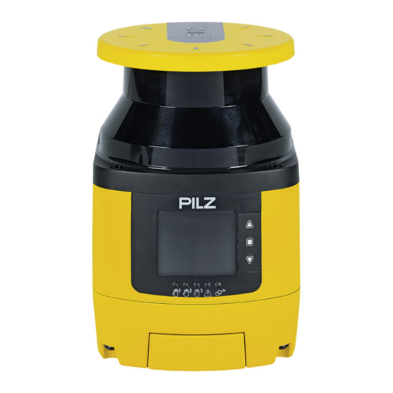
[3] Display for device messages [4] LEDs as status indicator [5] Buttons for scrolling in the display or to confirm the message in the display Scroll up Confirm message in the display Scroll down Operating Manual PSEN sc ME 5.5 08-17 | 10 1005388-EN-01... - Page 11 Locking Lights up yellow and lights up red: No object detected in safety zone, PSEN sc ME 5.5 08-17 waits for manual restart off and lights up green: No object detected in safety zone, PSEN sc ME 5.5 08-17 is ready for operation...
-
Page 12: Safety
Safety Safety Intended use The safety laser scanners of the PSEN sc ME 5.5 08-17 are electrosensitive protective equipment of ESPE type 3. They are used to protect personnel and systems. The safety laser scanners are designed to safeguard the danger zone, secure hazardous areas of vehicles and protect the access within buildings. -
Page 13: Safety Regulations
In safety-related applications, please comply with the mission time T in the safety-related characteristic data. When decommissioning, please comply with local regulations regarding the disposal of electronic devices (e.g. Electrical and Electronic Equipment Act). Operating Manual PSEN sc ME 5.5 08-17 | 13 1005388-EN-01... -
Page 14: For Your Safety
INFORMATION Laser radiation of the safety laser scanner The safety laser scanner of the PSEN sc ME 5.5 08-17 corresponds to the laser class 1 in accordance with EN 60825-1. Additional measures to shield the laser beams are not required (eye-safe). -
Page 15: Function Description
When at least one warning output was selected during the configuration of outputs, actions can be triggered (e.g. switching on indicator light unit), when an object or a person enters the warning zone. Operating Manual PSEN sc ME 5.5 08-17 | 15 1005388-EN-01... -
Page 16: Series Connection
When an object or a person intrudes into the warning zone or safety zone, the status of the relevant safety laser scanner is changed, shown in the display and signalled to the master. Depending on the violated zone, the master triggers the relevant configured actions. Operating Manual PSEN sc ME 5.5 08-17 | 16 1005388-EN-01... -
Page 17: Stationary And Mobile Danger Zone
Control of the slave units in accordance with the functionality configured in PSENscan Configurator In a series connection, the safety outputs of a safety laser scanner PSEN sc ME 5.5 08-17 are connected to an evaluation device. On this safety laser scanner, max. three safety laser scanners PSEN sc S 3/5 can be connected in series. - Page 18 If a violation of the warning zone is detected, the actions configured in PSENscan Configur- ator are performed. A visual or audible signal can be activated as advance warning. When using 2 warning zones, different reactions can be configured. Operating Manual PSEN sc ME 5.5 08-17 | 18 1005388-EN-01...
-
Page 19: Horizontal Application
Fig.: Application example PSENscan safety laser scanner - horizontal configuration Legend [1] Warning zone [2] Safety zone 4.2.2 Vertical application Fig.: Application example PSENscan safety laser scanner - vertical configuration Legend [1] Protective zone Operating Manual PSEN sc ME 5.5 08-17 | 19 1005388-EN-01... -
Page 20: Mobile Application
For vertical applications, national and international standards recommend monitoring a ref- erence outline. The reference outline is configured during the first installation of PSEN sc ME 5.5 08-17. The distances measured during configuration are used as reference values for monitoring the reference outline. -
Page 21: Automatic And Monitored Start/Restart
Max. number of inputs for switching zone sets – PSEN sc ME 5.5 08-17 with use of 8-pin connection: 3 – PSEN sc ME 5.5 08-17 with use of 17-pin connection: 20 – PSEN sc ME 5.5 08-17 with use of 17+8-pin connection: 70 Max. -
Page 22: Manual Restart
The reset pushbutton has to be connected to the reset input. To trigger a reset, the reset pushbutton has to be pressed for at least 500 ms. Operating Manual PSEN sc ME 5.5 08-17 | 22 1005388-EN-01... -
Page 23: Encoder
10 seconds after an error state is determined. The automatic reset function is permanently deactivated when the PSEN sc ME 5.5 08-17 switches to an error state more than 5 times within 15 minutes with an INTFx error. -
Page 24: Wave
In a rest condition the functions of the safety laser scanner are deactivated to save energy. This enables the use of the safety laser scanner with a supply voltage by battery (e.g. in an automated guided vehicle system). Operating Manual PSEN sc ME 5.5 08-17 | 24 1005388-EN-01... -
Page 25: Muting
– Dynamic muting: Available for L muting and T muting In addition to the conditions for L muting and T muting, activation and deactivation of the muting state can be controlled by the connected safety controller. Operating Manual PSEN sc ME 5.5 08-17 | 25 1005388-EN-01... -
Page 26: Override
Condition for the override function The override function can be started when the following conditions are met: The safety laser scanner is in a safe condition At least one muting sensor is active Operating Manual PSEN sc ME 5.5 08-17 | 26 1005388-EN-01... -
Page 27: Multiple Evaluation
A report includes all the settings that are valid for a configuration. A report must be checked for correctness and it can be saved as PDF and printed to a con- nected printer. Operating Manual PSEN sc ME 5.5 08-17 | 27 1005388-EN-01... -
Page 28: Project Configuration
Overall time from the occurrence of a safety zone violation to the complete stop of the machine The value is separated for the calculation in t1 and t2, with T = t + t Operating Manual PSEN sc ME 5.5 08-17 | 28 1005388-EN-01... -
Page 29: Horizontal Application With Stationary Danger Zone
[4] Minimum distance to the danger zone (corresponds max. to the operating range of the safety laser scanner) The following applies for these applications: S = K * (t ) + Z Operating Manual PSEN sc ME 5.5 08-17 | 29 1005388-EN-01... - Page 30 When the safety laser scanner is to be placed at a height of H > 300 mm, there is a risk of creeping underneath the safety zone. This is to be taken into account in the risk assess- ment, and if required additional protective measures must be taken. Operating Manual PSEN sc ME 5.5 08-17 | 30 1005388-EN-01...
-
Page 31: Horizontal Application With Automated Guided Vehicle Systems
Overall response time of the safety laser scanner in seconds (see Calculation of the overall response time [ 34]) Time between the violation of a protective zone and signal change at the OSSD out- put on the safety laser scanner Operating Manual PSEN sc ME 5.5 08-17 | 31 1005388-EN-01... - Page 32 Please note: Height of the scan plane Pilz recommends a scan plane height of 15 cm. A person lying on the floor is detected. A lower height would lead to reduced availability because of the increased dust formation on the floor.
-
Page 33: Vertical Application
The following applies for these applications: S = K * (t ) + Z Minimum distance in mm, measured from the start of the protective zone to the danger source Operating Manual PSEN sc ME 5.5 08-17 | 33 1005388-EN-01... -
Page 34: Calculation Of The Overall Response Time
In the PSENscan Configurator the automatic assignment ensures a difference in exactly two positions. Pilz recommends that the automatic assignment by the PSENscan Configurator is used. Operating Manual PSEN sc ME 5.5 08-17 | 34... -
Page 35: Monitoring Of Reference Outlines
The outline must be outside the protective zone and it consists of at least 3 and a max. of 15 reference points. When PSEN sc ME 5.5 08-17 detects a change of the outline, the safety laser scanner switches the OSSDs to the OFF state. A change in the area of a tolerance that can be set in PSENscan Configurator is accepted. - Page 36 Fig.: Using a reference outline for protecting a moveable construction Legend Danger zone Area covered by the safety laser scanner Safety laser scanner Reference points Moveable construction that is protected by the reference points Operating Manual PSEN sc ME 5.5 08-17 | 36 1005388-EN-01...
-
Page 37: Area With Limited Detection Capability
Please note: Ensure that the area is not part of the danger zone. Install the safety laser scanner so that no objects can enter the zone with limited detec- tion capability. Operating Manual PSEN sc ME 5.5 08-17 | 37 1005388-EN-01... -
Page 38: Installation Of Several Adjacent Safety Laser Scanners
Without coding: Install safety laser scanner at various heights or inclination. Change the height of the safety laser scanners Change the inclination of the safety laser scanners. Place an opaque object between the safety laser scanners Operating Manual PSEN sc ME 5.5 08-17 | 38 1005388-EN-01... -
Page 39: Ambient Conditions
When operating the safety laser scanner, avoid strong smoke, mist, and dust formation that would reduce the safety laser scanner's operating range or lead to switching to the OFF state. Operating Manual PSEN sc ME 5.5 08-17 | 39 1005388-EN-01... -
Page 40: Dust Filtration
Distance to intense light sources and to reflective surfaces Minimum distance to especially intense or flashing light sources Pilz recommends that the safety laser scanner is not installed near particularly intense or flashing light sources (e.g. flash units). When especially intense or flashing light sources are near the safety laser scanner (area of +/- 5°... - Page 41 [2] Area of +/- 5° to the scanning plane Minimum distance from reflective surfaces Pilz recommends that reflective surfaces with a distance of 3 m to the safety zone are re- moved. If this is not possible, the allowance Z must be considered when calculating the safety distance.
-
Page 42: Distance From Walls
Determined speed is in the range of -30 cm/s to -10 cm/s or in the range of 10 cm/s to 30 cm/s: Exceeding is permitted for max. 60 s The determined speed is ≤ -30 cm/s or ≥ 30 cm/s: Exceeding is permitted for max. 20 s Operating Manual PSEN sc ME 5.5 08-17 | 42 1005388-EN-01... - Page 43 Speed maximum and minimum – Formula for the max. permitted speed /Anz ImpFZWeg = 100,000 and it corresponds to the max. frequency that PSEN sc ME 5.5 08-17 can read. In the example, 100,000/63.66 = 1,570.845. – Formula for the min. permitted speed = - F...
-
Page 44: Determining The Moment Of Switchover
Advance of the switchover time when using inputs of another device Advance of the switchover time when using inputs of external OSSDs [1] Monitoring zone set 1 is active [2] Monitoring zone set 2 is active Operating Manual PSEN sc ME 5.5 08-17 | 44 1005388-EN-01... -
Page 45: Muting
The muting state is shown by the muting lamp and in the display of PSEN sc ME 5.5 08-17. The muting lamp must be connected to the PSEN sc ME 5.5 08-17 and positioned so that the muting lamp is clearly visible form the whole danger zone. -
Page 46: Muting In Two Directions
Internal delay before the ending of the muting state (max. 30 ms) Delay between Muting 1 and Muting 2 (configurable from 1-16 s) Duration of the muting state (max. up to the configurable time exceeded) Operating Manual PSEN sc ME 5.5 08-17 | 46 1005388-EN-01... - Page 47 (max. 4 s after the first sensor was passed). Muting lamp flashes, signalling the muting state. Material on the conveyor passes the PSEN sc ME 5.5 08-17 and the first muting sensor on the output side, muting lamp flashes, signalling the muting state.
- Page 48 Distance that the object covers from the first muting sensor A1 to the second mut- ing sensor B2 in max. 4 s V Speed at which the object is moving Operating Manual PSEN sc ME 5.5 08-17 | 48 1005388-EN-01...
-
Page 49: Muting In One Direction
Delay between Muting 1 and Muting 2 (configurable from 1-16 s) Duration of the muting state (max. up to the configurable time exceeded) Internal delay before the ending of the muting state (max. 30 ms) Operating Manual PSEN sc ME 5.5 08-17 | 49 1005388-EN-01... - Page 50 Material passes the second muting sensor (max. 4 s after the first sensor was passed). Muting lamp flashes, signalling the muting status. Material passes the PSEN sc ME 5.5 08-17 and the first muting sensor on the output side, muting lamp flashes, signalling the muting status.
-
Page 51: Dynamic Muting
– When configuring the inputs, Activate muting is configured for this input in PSENscan Configurator – the first sensor has detected conveyed material and the second sensor also detected it max. 4 s afterwards Operating Manual PSEN sc ME 5.5 08-17 | 51 1005388-EN-01... -
Page 52: Override
Fig.: Timing diagram for override function single-channel pulses Condition Override 24 V Override 2 24 V Override 1 Status Override t < 400 ms Fig.: Timing diagram for override function edge-triggered Operating Manual PSEN sc ME 5.5 08-17 | 52 1005388-EN-01... -
Page 53: Rest Condition
The master unit displays the error INTF18, the slave units are in normal operation. Now change the structure of the arrangement of safety laser scanners. Operating Manual PSEN sc ME 5.5 08-17 | 53 1005388-EN-01... -
Page 54: Wiring
The safety laser scanner PSEN sc ME 5.5 08-17 has configurable inputs and outputs. In PSENscan Configurator these can be configured for the specific application. The safety laser scanner PSEN sc ME 5.5 08-17 has an 8-pin male connector and a 17-pin male connector for connection to the evaluation device and the supply voltage. - Page 55 – Two configurable inputs/outputs can be used as a 3. OSSD pair Pin/colour Description Brow 24 V DC Blue 0 V DC Green Configurable input Yel- Configurable input White Configurable input/output Grey OSSD 11 Pink OSSD 12 Operating Manual PSEN sc ME 5.5 08-17 | 55 1005388-EN-01...
- Page 56 The configurable inputs and outputs can be used for both input signals and output signals. The configurable inputs can be used for all input signals. Restart and reset EDM (when using the 17-pin connection) Switching the monitoring of zone sets Dynamic and static muting Operating Manual PSEN sc ME 5.5 08-17 | 56 1005388-EN-01...
-
Page 57: Connector Assignment Slave Unit
Wiring Connector assignment slave unit The slave unit of the safety laser scanners PSEN sc ME 5.5 08-17 has two 8-pin M12 sock- ets for connecting to the master unit or to a different slave unit. In PSENscan Configurator this configuration also has to be made when creating a new configuration. -
Page 58: Wiring Of The Configurations
The supply voltage connection is in the memory module that is protected by a screwed-on cover. The memory module can be uninstalled for simpler connection. 1. Turn the safety laser scanner PSEN sc ME 5.5 08-17 for better access to the memory module. - Page 59 The screws are secured against loss and they cannot be removed. Legend [1] M3 screws for fixing the memory module 4. Connect the supply voltage and the safety controller to the 8-pin or the 12-pin socket on the memory module. Operating Manual PSEN sc ME 5.5 08-17 | 59 1005388-EN-01...
-
Page 60: Connection To Psenscan Configurator
Please note: Ensure that the software PSENscan Configurator is installed on the configuration PC. We recommend that you always use the latest version (download from www.pilz.com) Ensure that the safety laser scanner is switched off when creating a connection to the configuration PC. -
Page 61: Single Connection
Wiring For use in an industrial environment, Pilz recommends double-shielded twisted pair cables (S/STP). Only shielded RJ45 connectors should be used. Twisted pair cables (TP cable) consist of twisted core-pairs. Twisted pair cables are divided into categories in accordance with their electrical features (attenuation, cross-talk). Cat- egory 5 cables are specified for transferring data with Pilz Ethernet interfaces. -
Page 62: Series Connection
[ 77]. Use a 17-pin cable or both cables (see Order references [ 123]). 4. Switch the safety laser scanner on. Configure the safety laser scanner in PSENscan Configurator. [ Operating Manual PSEN sc ME 5.5 08-17 | 62 1005388-EN-01... -
Page 63: Connections For Muting Sensors
Connection: 17-pin 5, 6, 7, 9, 14, 17 Connection: 8-pin 5, 6, 7, 9, 14, 17 8-1 to 8-8 and 17-pin Fig.: Wiring of 4 muting sensors on the master unit Operating Manual PSEN sc ME 5.5 08-17 | 63 1005388-EN-01... -
Page 64: Installation And Alignment
[ 42]. To fix the safety laser scanner, use M5 screws for a max. screw depth of 10 mm. Legend [1] Mounting surface [2] M5 screws Operating Manual PSEN sc ME 5.5 08-17 | 64 1005388-EN-01... -
Page 65: Installation Of The Protective Bracket Psen Sc Bracket H At The Safety Laser Scanner
3 Nm. Legend PSEN sc bracket H (protective bracket for safety laser scanner) M5 screws for fixing the PSEN sc bracket H at the safety laser scanner PSEN sc bracket H installed at the safety laser scanner Operating Manual PSEN sc ME 5.5 08-17 | 65 1005388-EN-01... -
Page 66: Installation On The Floor
The setting of the angle of inclination of the safety laser scanner is not changed when ex- changing the safety laser scanner. Prerequisites Mounting surface with 2 drill holes, 10 mm deep, distance 73 mm horizontally towards each other for fixing the PSEN sc bracket PR or PSEN sc bracket P Operating Manual PSEN sc ME 5.5 08-17 | 66 1005388-EN-01... - Page 67 4. Align the middle of the adjusting disc for angle of inclination [1] with the center of the fix- ing for the safety laser scanner [3] and tighten the set screw for the adjusting disc for angle of inclination [2] with 2,5 Nm. Operating Manual PSEN sc ME 5.5 08-17 | 67 1005388-EN-01...
- Page 68 PSEN sc bracket H to the top and fix the safety laser scanner with the screws [3] and [4]. Tighten all four screws to 3 Nm. Inclination to the top/bottom Inclination to the side (roll) Operating Manual PSEN sc ME 5.5 08-17 | 68 1005388-EN-01...
-
Page 69: Installation With Angle Of Inclination Setting - Holder Psen Sc Bracket P
[2] with 2,5 Nm. Set the angle of inclination of the safety laser scanner Procedure: 1. Change the inclination of the safety laser scanner within the permitted range of ± 6°. Operating Manual PSEN sc ME 5.5 08-17 | 69 1005388-EN-01... -
Page 70: Set The Side Inclination Of The Safety Laser Scanner
2. Tighten the roll angle fine adjustment screws [7] (see figure Installation with setting of angle of inclination/roll angle - bracket PSEN sc bracket P [ 66]) with 2,5 Nm. Operating Manual PSEN sc ME 5.5 08-17 | 70 1005388-EN-01... -
Page 71: Measures To Safeguard Unsecured Areas
Installation and alignment Measures to safeguard unsecured areas When installing the PSEN sc ME 5.5 08-17 areas may result that are not detected by the safety laser scanner. If required, install additional protective devices to safeguard the danger zone. Prevent stepping behind... - Page 72 Installation and alignment Prevent creeping underneath Legend [1] Mounting surface [2] Scanning plane [3] Base area [4] Safeguard area against creeping underneath [5] Edge at the mounting surface Operating Manual PSEN sc ME 5.5 08-17 | 72 1005388-EN-01...
-
Page 73: Psenscan Configurator
For incorporation of the safety laser scanner into the network, For monitoring the safety laser scanners in the network, For creating reports, For password administration of the safety laser scanner of the PSEN sc ME 5.5 08-17 Installation 8.2.1 System requirements... -
Page 74: Ethernet Connections
The PSENscan Configurator offers the option of automatically finding a device available in the network. 1. Select Device -> Search device. The network is searched for connected devices of the PSEN sc ME 5.5 08-17. Connected devices of the PSEN sc ME 5.5 08-17 are listed under Network environ- ment. -
Page 75: Download Configuration To Device
Create backup copy of a configuration For restoring an existing configuration (see Restore configuration [ 103]) you need a backup copy of this configuration. Operating Manual PSEN sc ME 5.5 08-17 | 75 1005388-EN-01... -
Page 76: Manage Password
Take down the counter shown and the serial number of the safety laser scanner. Do not close the window unless you have a new password. 2. For resetting the password, please contact Pilz. Name the counter shown and the serial number of the safety laser scanner. -
Page 77: First Commissioning
F.E. PSENscan Fig.: Dual-channel connection of the safety laser scanner with 8-pin male connector on the input cir- cuit of an evaluation device (1 zone set, warning message, automatic restart) Operating Manual PSEN sc ME 5.5 08-17 | 77 1005388-EN-01... -
Page 78: Configuration Of Zones
When these inputs/outputs are used, a pin has to be assigned for each used input or out- put. Outputs – Warning – Alarm 1 – Alarm 2 – Override status – Muting lamp Operating Manual PSEN sc ME 5.5 08-17 | 78 1005388-EN-01... -
Page 79: Example For An 8-Pin Connection
The Check sum is entered by the system and cannot be changed. The Creation date is entered by the system and cannot be changed. Device You can enter a title for the connected device under Name. Operating Manual PSEN sc ME 5.5 08-17 | 79 1005388-EN-01... - Page 80 10. Under Multiple evaluation, define the number of consecutive scans needed for detec- tion. Increasing the number of consecutive scans will increase the response time of the safety laser scanner. Operating Manual PSEN sc ME 5.5 08-17 | 80 1005388-EN-01...
- Page 81 Tol + is the tolerance for the side that is facing away from the safety laser scanner. 18. Switch the display in the work window to a live image by clicking on Operating Manual PSEN sc ME 5.5 08-17 | 81...
-
Page 82: Example For A 17-Pin Connection
The Check sum is entered by the system and cannot be changed. The Creation date is entered by the system and cannot be changed. Device You can enter a title for the connected device under Name. Safety laser scanner arrangement Operating Manual PSEN sc ME 5.5 08-17 | 82 1005388-EN-01... - Page 83 Note when mapping manually: Zone sets where a 0 or 1 is entered for all the zone switching, are not permitted. Automatic coding using PSENscan Configurator Click for automatic coding of zone sets Click on the arrow . The next window Input configuration is opened. Operating Manual PSEN sc ME 5.5 08-17 | 83 1005388-EN-01...
- Page 84 Detection capability 50 mm = 23 m Detection capability ≥ 70 mm = 40 m 13. Select Dust filter level (level 1 = low, level 3 = high). A higher level of dust filtering requires a longer safety distance. Operating Manual PSEN sc ME 5.5 08-17 | 84 1005388-EN-01...
- Page 85 18. Select Download configuration to device, to transfer the configuration to the device. Click Accept to activate the downloaded configuration in the connected device and re- ject the existing configuration on the connected device. Operating Manual PSEN sc ME 5.5 08-17 | 85 1005388-EN-01...
-
Page 86: Example For A 17+8-Pin Connection
The pins 8 and 13 are reserved for the first OSSD pair and they cannot be changed. For OSSD, select 2x2. Two of the remaining outputs are reserved for the second OSSD pair. Operating Manual PSEN sc ME 5.5 08-17 | 86 1005388-EN-01... - Page 87 In the first safety zone, select the settings for muting. In the first safety zone select Override = Activated and Override mode = Edge. Select 2 outputs for muting, and also for override and override mode. Operating Manual PSEN sc ME 5.5 08-17 | 87 1005388-EN-01...
- Page 88 Detection capability 50 mm = 23 m Detection capability ≥ 70 mm = 40 m 13. Select Dust filter level (level 1 = low, level 3 = high). A higher level of dust filtering requires a longer safety distance. Operating Manual PSEN sc ME 5.5 08-17 | 88 1005388-EN-01...
- Page 89 18. Select Download configuration to device, to transfer the configuration to the device. Click Accept to activate the downloaded configuration in the connected device and re- ject the existing configuration on the connected device. Operating Manual PSEN sc ME 5.5 08-17 | 89 1005388-EN-01...
-
Page 90: Example For A 17+8-Pin Connection With Encoder Inputs
The pins 8 and 13 are reserved for the first OSSD pair and they cannot be changed. For OSSD, select 2x2. Two of the remaining outputs are reserved for the second OSSD pair. Operating Manual PSEN sc ME 5.5 08-17 | 90 1005388-EN-01... - Page 91 8. In the first safety zone, for Restart select the value Manual and assign a pin to the manual restart. For Restart select the value Automatic in the second safety zone and define the re- start time (min. 80 ms). Operating Manual PSEN sc ME 5.5 08-17 | 91 1005388-EN-01...
- Page 92 Detection capability 50 mm = 23 m Detection capability ≥ 70 mm = 40 m 13. Select Dust filter level (level 1 = low, level 3 = high). A higher level of dust filtering requires a longer safety distance. Operating Manual PSEN sc ME 5.5 08-17 | 92 1005388-EN-01...
- Page 93 18. Select Download configuration to device, to transfer the configuration to the device. Click Accept to activate the downloaded configuration in the connected device and re- ject the existing configuration on the connected device. Operating Manual PSEN sc ME 5.5 08-17 | 93 1005388-EN-01...
-
Page 94: Testing
It must not be possible to operate the pushbutton for manual restart from inside the danger zone. The pushbutton must be located at a position from which there is a full, un- obstructed view of the danger zone. Operating Manual PSEN sc ME 5.5 08-17 | 94 1005388-EN-01... - Page 95 Procedure: Select Project -> Save. The dialogue box for saving is opened. Please enter a name for the MIB file. The MIB file includes all the data for configuration. Operating Manual PSEN sc ME 5.5 08-17 | 95 1005388-EN-01...
-
Page 96: Operation
Decommission the safety laser scanner. Clean the safety laser scanner’s front panel [ 106]. DLDNC Download of a configuration or a re- A configuration or a report is port downloaded. Operating Manual PSEN sc ME 5.5 08-17 | 96 1005388-EN-01... - Page 97 The OSSDs are in the ON state. OVERRIDE ERR Could not activate override because the specifications for activation were not met. OVERRIDE Override is active. OVR TIMEOUT Override has elapsed. Operating Manual PSEN sc ME 5.5 08-17 | 97 1005388-EN-01...
-
Page 98: Diagnostic Information
If the error persists, please contact Pilz. INTF7 An error occurred during the system Perform a reset of the safety laser test. scanner [ 104]. If the error persists, please contact Pilz. Operating Manual PSEN sc ME 5.5 08-17 | 98 1005388-EN-01... - Page 99 If the error persists, please contact Pilz. INTF17 An error occurred during the system Perform a reset of the safety laser test. scanner [ 104]. If the error persists, please contact Pilz. Operating Manual PSEN sc ME 5.5 08-17 | 99 1005388-EN-01...
-
Page 100: Warnings
HIGH REFL- The reflection of the background is Reduce the background reflection or too strong. increase the safety distance (see Distance to intense light sources and to reflective surfaces [ 40]). Operating Manual PSEN sc ME 5.5 08-17 | 100 1005388-EN-01... -
Page 101: Information
An entry is created in the log file for each logged event. Format of the entries: <Date> <Time> <Event type <Details on the event> Example of a mistake: 10-Sep-20 5:24:30 PM;FAULT;FAULT INPUTCF2 Operating Manual PSEN sc ME 5.5 08-17 | 101 1005388-EN-01... -
Page 102: Text Messages In The Display
10.4 Text messages in the display With the buttons under the display of PSEN sc ME 5.5 08-17 you can navigate in the mes- sage in the display. Confirm message in the display and open the next menu level or exit the last... -
Page 103: Restore Configuration
The MIB files in PSEN sc ME 5.5 08-17 and in the memory module are different. The topologies in PSEN sc ME 5.5 08-17and in the memory module are different. The serial numbers saved in PSEN sc ME 5.5 08-17 and in the memory module are dif- ferent. -
Page 104: Reset
With the reset function, the safety laser scanner can be set to normal operation when the safety laser scanner is in an error state, and the error was rectified. Procedure: Hold the reset pushbutton down for at least 500 ms. Operating Manual PSEN sc ME 5.5 08-17 | 104 1005388-EN-01... -
Page 105: Activate Rest Condition
Select Rest condition = Deactivated. 2. After approx. 30 seconds the safety laser scanner is again in normal operation. The display and the LEDs of the safety laser scanner show normal operation. Operating Manual PSEN sc ME 5.5 08-17 | 105 1005388-EN-01... -
Page 106: Safety Checks, Maintenance And Repair
Improper cleaning agents can damage the front screen and lead to faulty shutdowns. – Use only the cleaning agents specified. A scratched front panel can lead to faulty shutdowns of the safety laser scanner. Contact Pilz and exchange the PSEN sc head when the front panel is scratched. Contamination Cleaning Finger marks Dampen PSEN sc cloth with PSEN sc cleaner (see... -
Page 107: Checks
Regular check Regular checks can bring to light changes to the plant/machine, safeguards and ambient conditions. Pilz recommends that the safety laser scanner be checked every six months. Check the safety laser scanner’s front panel. – Scratched front panel: Exchange the PSEN sc head [ 107]. - Page 108 PSEN sc head upwards. While doing so, do not damage the PSEN sc head by colli- sions with other components. 3. Replace the old seal with the new seal. Ensure that the new seal is seated correctly in the seal seat. Operating Manual PSEN sc ME 5.5 08-17 | 108 1005388-EN-01...
- Page 109 40 mm at a distance of 1 m to the safety laser scanner over the complete scanning area of 275° (see Check the safety function of the safety laser scanner [ 94]). 15. Switch the safety laser scanner off. Operating Manual PSEN sc ME 5.5 08-17 | 109 1005388-EN-01...
- Page 110 Install the safety laser scanner as it was installed before exchanging the PSEN sc head. 19. Switch the safety laser scanner on. 20. In PSENscan Configurator select Device -> Exchange PSEN sc head. Confirm the exchange of PSEN sc head with Finish. Operating Manual PSEN sc ME 5.5 08-17 | 110 1005388-EN-01...
-
Page 111: Dimensions
Dimensions Dimensions Master unit 59.5 112.5 M5x8 (4x) Side view Plan view Rear view View from below with protective cover Operating Manual PSEN sc ME 5.5 08-17 | 111 1005388-EN-01... - Page 112 Dimensions Slave unit 59.5 112.5 M5x8(4x) Side view Plan view Rear view View from below with protective cover Operating Manual PSEN sc ME 5.5 08-17 | 112 1005388-EN-01...
- Page 113 Dimensions PSEN sc bracket P 119,2 110,4 Front view 72,5 Side view PSEN sc bracket PR Front view Side view Operating Manual PSEN sc ME 5.5 08-17 | 113 1005388-EN-01...
- Page 114 Dimensions PSEN sc bracket F 39,5 Operating Manual PSEN sc ME 5.5 08-17 | 114 1005388-EN-01...
-
Page 115: Technical Details Order No. 6D000034
Pulse duration 3 ns Typical output power laser 8 mW Inputs Number of configurable inputs Number of configurable inputs/outputs Number of speed inputs Signal level at "0" < 5 V Operating Manual PSEN sc ME 5.5 08-17 | 115 1005388-EN-01... - Page 116 EN 60068-2-6 Frequency 10 - 55 Hz Amplitude 0,35 mm Shock stress In accordance with the standard EN 60068-2-27 Number of shocks 1000 Acceleration Duration 16 ms Protection type Housing IP65 Operating Manual PSEN sc ME 5.5 08-17 | 116 1005388-EN-01...
- Page 117 Fixing screw 3 Nm Adjusting screw for angle of inclination 2,5 Nm PSEN sc Memory 1 Nm Dimensions Height 152 mm Width 102 mm Depth 112,5 mm Weight 1.530 g Operating Manual PSEN sc ME 5.5 08-17 | 117 1005388-EN-01...
-
Page 118: Technical Details Order No. 6D000020-6D000021
0,1° Max. number multiple evaluation Detectable remission area 1,8 - 1.000 % 1,8 - 1.000 % Pulse duration 3 ns 3 ns Typical output power laser 8 mW 8 mW Operating Manual PSEN sc ME 5.5 08-17 | 118 1005388-EN-01... - Page 119 0,35 mm 0,35 mm Shock stress In accordance with the standard EN 60068-2-27 EN 60068-2-27 Number of shocks 1000 1000 Acceleration Duration 16 ms 16 ms Protection type Housing IP65 IP65 Operating Manual PSEN sc ME 5.5 08-17 | 119 1005388-EN-01...
- Page 120 2,5 Nm PSEN sc Memory 1 Nm 1 Nm Dimensions Height 152 mm 152 mm Width 102 mm 102 mm Depth 112,5 mm 112,5 mm Weight 1.530 g 1.530 g Operating Manual PSEN sc ME 5.5 08-17 | 120 1005388-EN-01...
-
Page 121: Safety Characteristic Data
A safety function's SIL/PL values are not identical to the SIL/PL values of the units that are used and may be different. We recommend that you use the PAScal software tool to calculate the safety function's SIL/PL values. Operating Manual PSEN sc ME 5.5 08-17 | 121 1005388-EN-01... -
Page 122: Network Data
User interface proprietary in/out 3000 Receive command User interface proprietary in/out 4088 Find device in network User interface proprietary In/out 12000 Poll configur- ation data Information for data ex- change Operating Manual PSEN sc ME 5.5 08-17 | 122 1005388-EN-01... -
Page 123: Order Reference
M12-8sm/ nector, nector, M12-8sm, 5m straight straight PSEN sc cable 10 m M12, 8-pin M12, 8-pin 6D000025 CAT5e male con- male con- M12-8sm/ nector, nector, M12-8sm, 10m straight straight Operating Manual PSEN sc ME 5.5 08-17 | 123 1005388-EN-01... - Page 124 50 m M12, 17-pin 6D000033 M12-17sf, 50m female con- nector, straight PSEN op Ether- M12, 4-pin 4-pin RJ45 631071 net cable 1m male con- male con- nector, nector, straight straight Operating Manual PSEN sc ME 5.5 08-17 | 124 1005388-EN-01...
- Page 125 Order no. M12 con., straight, D-coded M12, 4-pin 380316 male, 4-pin, D male con- nector, straight SafetyNET p con- 4-pin RJ45 380400 nector RJ45s male con- nector, straight, Cat 5a Operating Manual PSEN sc ME 5.5 08-17 | 125 1005388-EN-01...
-
Page 126: Appendix
Appendix 18.1 Check list The check list below is intended as an aid in for the following work on a safety laser scan- ner of the PSEN sc ME 5.5 08-17: During commissioning, recommissioning, and running the specified regular check. - Page 127 Check the effectiveness of the safety laser scanner during the haz- ardous movement Is the safety laser scanner effective throughout the whole of the hazardous movement of the plant/machine? Operating Manual PSEN sc ME 5.5 08-17 | 127 1005388-EN-01...
- Page 128 The OSSDs must switch to the OFF state with each change of the refer- ence point beyond the tolerance range. Switch off the safety laser scanner Is the hazardous movement stopped immediately when you switch off? Operating Manual PSEN sc ME 5.5 08-17 | 128 1005388-EN-01...
-
Page 129: Identification
C = March I = September D = April L = October E = May M = November F = June N = December ##### Consecutive number within the month Operating Manual PSEN sc ME 5.5 08-17 | 129 1005388-EN-01... -
Page 130: Ec Declaration Of Conformity
European Parliament and of the Council. The complete EC Declaration of Conformity is available on the Internet at www.pilz.com/downloads. Authorised representative: Norbert Fröhlich, Pilz GmbH & Co. KG, Felix-Wankel-Str. 2, 73760 Ostfildern, Germany Operating Manual PSEN sc ME 5.5 08-17... - Page 131 We are represented internationally. Please refer to our homepage www.pilz.com for further details or contact our headquarters. Headquarters: Pilz GmbH & Co. KG, Felix-Wankel-Straße 2, 73760 Ostfildern, Germany Telephone: +49 711 3409-0, Telefax: +49 711 3409-133, E-Mail: info@pilz.com, Internet: www.pilz.com...
Need help?
Do you have a question about the PSEN sc ME 5.5 08-17 and is the answer not in the manual?
Questions and answers