Sungrow SG5.0RT User Manual
3-phase pv grid-connected inverter
Hide thumbs
Also See for SG5.0RT:
- Manual (6 pages) ,
- User manual (153 pages) ,
- Quick installation manual (48 pages)

Related Manuals for Sungrow SG5.0RT


Summary of Contents for Sungrow SG5.0RT
- Page 1 3-Phase PV Grid-Connected Inverter User Manual SG5.0RT / SG6.0RT / SG7.0RT / SG8.0RT / SG10RT / SG12RT / SG15RT / SG17RT / SG20RT WWW.SUNGROWPOWER.COM SG5.0-20RT-UEN-Ver13-202101...
-
Page 3: All Rights Reserved
It is prohibited to use data contained in firmware or software developed by • SUNGROW, in part or in full, for commercial purposes by any means. It is prohibited to perform reverse engineering, cracking, or any other operations that •... -
Page 4: About This Manual
. . s s u u n n g g r r o o w w p p o o w w e e r r . . c c o o m m or on the webpage of the respective component manufacturer. V V a a l l i i d d i i t t y y This manual is valid for the following inverter models: SG5.0RT • SG6.0RT • SG7.0RT •... - Page 5 S S y y m m b b o o l l s s Important instructions contained in this manual should be followed during installation, operation and maintenance of the inverter. They will be highlighted by the following symbols. Indicates a hazard with a high level of risk that, if not avoided, will result in death or serious injury.
-
Page 7: Table Of Contents
C C o o n n t t e e n n t t s s All Rights Reserved .....................I About This Manual .....................II 1 Safety ......................1 1.1 PV Panels..................... 1 1.2 Utility Grid ....................1 1.3 Inverter ......................2 2 Product Description .................. - Page 8 5.5.2 Assembling the AC Connector (< 15 kW) .......... 25 5.5.3 Installing the AC Connector (< 15 kW)..........27 5.5.4 Assembling the AC Connector (≥ 15 kW) ......... 28 5.5.5 Installing the AC Connector (≥ 15 kW)..........30 5.6 DC Cable Connection ................. 32 5.6.1 PV Input Configuration ..............
- Page 9 7.8 Records ..................... 64 7.9 More ......................67 7.9.1 System Parameters ................68 7.9.2 Operation Parameters............... 68 7.9.3 Power Regulation Parameters............69 7.9.4 Communication Parameters ............. 71 7.9.5 Firmware Update................71 8 System Decommissioning ..............73 8.1 Disconnecting the Inverter................73 8.2 Dismantling the Inverter................
-
Page 11: Safety
The safety instructions in this manual cannot cover all the precautions that should be followed. Perform operations considering actual onsite conditions. SUNGROW shall not be held liable for any damage caused by violation of the safety instructions in this manual. -
Page 12: Inverter
1 Safety User Manual All electrical connections must be in accordance with local and national standards. Only with the permission of the local utility grid company, the inverter can be connected to the utility grid. 1.3 Inverter Danger to life from electric shocks due to live voltage Do not open the enclosure at any time. - Page 13 User Manual 1 Safety Only qualified personnel can perform the country setting. Unauthorized alteration may cause a breach of the type-certificate marking. Risk of inverter damage due to electrostatic discharge (ESD)! By touching the electronic components, you may damage the inverter. For inverter handling, be sure to: avoid any unnecessary touching;...
-
Page 14: Product Description
I I t t e e m m N N o o t t e e Compatible with monocrystalline silicon, polycrystalline PV strings silicon, and thin-film without grounding SG5.0RT, SG6.0RT, SG7.0RT, SG8.0RT, SG10RT, SG12RT, Inverter SG15RT, SG17RT, SG20RT Metering device Meter cupboard with power distribution system Utility grid TT, TN-C,TN-S,TN-C-S... -
Page 15: Product Introduction
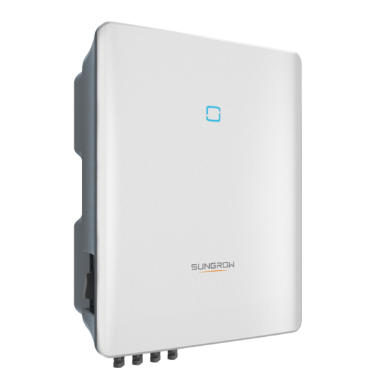
User Manual 2 Product Description 2.2 Product Introduction M M o o d d e e l l D D e e s s c c r r i i p p t t i i o o n n The model description is as follows (take SG10RT as an example): A A p p p p e e a a r r a a n n c c e e The following figure shows the dimensions of the inverter. - Page 16 2 Product Description User Manual F F i i g g u u r r e e 2 2 - - 2 2 Inverter Appearance D D e e s s c c r r i i p p t t i i o o n n N N o o .
-
Page 17: Symbols On The Product
User Manual 2 Product Description F F i i g g u u r r e e 2 2 - - 3 3 Dimensions of the Inverter(in mm) 2.3 Symbols on the Product S S y y m m b b l l o o E E x x p p l l a a n n a a t t i i o o n n Regulatory compliance mark. -
Page 18: Led Indicator
2 Product Description User Manual S S y y m m b b l l o o E E x x p p l l a a n n a a t t i i o o n n Danger to life due to high voltages! Do not touch live parts for 10 minutes after disconnection from the power sources. -
Page 19: Function Description
User Manual 2 Product Description F F i i g g u u r r e e 2 2 - - 4 4 Circuit Diagram (SG5.0RT for example) The DC switch is used to safely disconnect the DC circuit. •... - Page 20 2 Product Description User Manual Protection Function • Several protective functions are integrated in the inverter, including short circuit protection, grounding insulation resistance surveillance, residual current protection, anti-islanding protection, DC overvoltage/overcurrent protection, etc. F F a a u u l l t t A A l l a a r r m m The inverter has integrated a DO relay for the local fault alarm.
- Page 21 User Manual 2 Product Description Before enabling the PID recovery function, make sure the voltage polarity of • the PV modules to ground meets requirement. If there are any questions, contact the PV module manufacturer or read its corresponding user manual. If the voltage scheme for the PID recovery function does not meet the •...
-
Page 22: Unpacking And Storage
Check the inner contents for damage after unpacking. • Contact SUNGROW or the supplier in case of any damage or incompleteness. Do not dispose of the original packing case. It is recommended to store the device in it. 3.2 Inverter Storage Proper storage is required if the inverter is not installed immediately. -
Page 23: Mechanical Mounting
Mechanical Mounting 4.1 Safety during Mounting Make sure there is no electrical connection before installation. In order to avoid electric shock or other injury, make sure that holes will not be drilled over any electricity or plumbing installations. Risk of injury due to improper handling Always follow the instructions when moving and positioning the inverter. - Page 24 4 Mechanical Mounting User Manual The ambient temperature and relative humidity must meet the following • requirements. Avoid direct exposure to sun, rain and snow. • The inverter should be well ventilated. Ensure air circulation. • Never install the inverter in living areas. The inverter will generate noise during •...
- Page 25 User Manual 4 Mechanical Mounting C C l l e e a a r r a a n n c c e e R R e e q q u u i i r r e e m m e e n n t t s s Reserve enough clearance around the inverter to ensure sufficient space for heat dissipation.
-
Page 26: Installation Tools
4 Mechanical Mounting User Manual 4.3 Installation Tools Installation tools include but are not limited to the following recommended ones. If necessary, use other auxiliary tools on site. Table 4-1 Tool specification Goggles Earplugs Dust mask Protective gloves Insulated shoes Utility knife Marker Wrist strap... -
Page 27: Moving The Inverter
User Manual 4 Mechanical Mounting RJ45 crimping tool Vacuum cleaner Measuring tape Heat shrink tubing Slotted screwdriver 4.4 Moving the Inverter Before installation, remove the inverter from the packing case and move it to the installation site. Follow the instructions below as you move the inverter: Always be aware of the weight of the inverter. - Page 28 4 Mechanical Mounting User Manual The depth of the holes should be about 70 mm. Step 2 Place the expansion tubes into the holes. Then secure the wall-mounting bracket to the wall firmly with the expansion bolt sets. Step 3 Lift the inverter and slide it down along the wall-mounting bracket to make sure they match perfectly.
-
Page 29: Electrical Connection
Electrical Connection 5.1 Safety Instructions Prior to any electrical connections, keep in mind that the inverter has dual power supplies. It is mandatory for the qualified personnel to wear personal protective equipments (PPE) during the electrical work. Danger to life due to a high voltage inside the inverter! The PV string will generate lethal high voltage when exposed to sunlight. - Page 30 5 Electrical Connection User Manual F F i i g g u u r r e e 5 5 - - 1 1 Terminals (SG20RT for example) * The image shown here is for reference only. The actual product received may differ. Table 5-1 Terminal Description D D e e c c i i s s i i v v e e D D e e s s c c r r i i p p t t i i o o n n...
-
Page 31: Electrical Connection Overview
User Manual 5 Electrical Connection F F i i g g u u r r e e 5 5 - - 2 2 Label of COM2 Terminal Table 5-2 Label Description of COM2 Terminal D D e e s s c c r r i i p p t t i i o o n n L L a a b b e e l l RSD-1, Reserved... -
Page 32: Additional Grounding Connection
5.3 mm–7 mm 8 * 0.2 mm cable Meter Shielded twisted RS485 2 * (0.5–1.0) mm 5.3 mm–7 mm pair cable SG5.0RT to SG5.0RT to SG12RT:10 SG12RT:4 mm –6 Outdoor 5-core mm–21 mm AC cable copper wire cable SG15RT to SG15RT to SG20RT:14... -
Page 33: Additional Grounding Requirements
User Manual 5 Electrical Connection 5.4.1 Additional Grounding Requirements All non-current carrying metal parts and device enclosures in the PV power system should be grounded, for example, brackets of PV modules and inverter enclosure. When there is only one inverter in the PV system, connect the additional grounding cable to a nearby grounding point. -
Page 34: Ac Cable Connection
R R e e c c o o m m m m e e n n d d e e d d S S p p e e c c i i f f i i c c a a t t i i o o n n I I n n v v e e r r t t e e r r M M o o d d e e l l SG5.0RT/SG6.0RT 16 A SG7.0RT/SG8.0RT... -
Page 35: Assembling The Ac Connector (< 15 Kw)
M M u u l l t t i i p p l l e e I I n n v v e e r r t t e e r r s s i i n n p p a a r r a a l l l l e e l l C C o o n n n n e e c c t t i i o o n n If multiple inverters are connected in parallel to the grid, ensure that the total number of parallel inverters does not exceed 5. Otherwise, please contact SUNGROW for technical scheme. - Page 36 5 Electrical Connection User Manual Step 3 Thread the AC cable of appropriate length through the swivel nut, the sealing ring and the housing. Step 4 Remove the cable jacket by less than 45 mm, and strip the wire insulation by 12 mm– 16 mm.
-
Page 37: Installing The Ac Connector (< 15 Kw)
User Manual 5 Electrical Connection - - - - E E n n d d 5.5.3 Installing the AC Connector (< 15 kW) High voltage may be present in inverter! Ensure all cables are voltage-free before electrical connection. Do not connect the AC circuit breaker until all inverter electrical connections are completed. -
Page 38: Assembling The Ac Connector (≥ 15 Kw)
5 Electrical Connection User Manual Step 4 Connect the PE wire to ground and the phase lines and the “N” line to AC circuit breaker. Then Connect the AC circuit breaker to utility grid. Step 5 Make sure all wires are firmly installed via the right torque tool or dragging the cables slightly. - Page 39 User Manual 5 Electrical Connection Step 4 Thread the AC cable of appropriate length through the swivel nut and the housing. Step 5 Remove the cable jacket by 80 mm–90 mm, and strip the wire insulation by 12 mm. Step 6 ( ( O O p p t t i i o o n n a a l l ) ) When using a multi-core multi-strand copper wire cable, connect the AC wire head to the cord end terminal (hand-tight).
-
Page 40: Installing The Ac Connector (≥ 15 Kw)
5 Electrical Connection User Manual Observe the plug assignment. Do not connect any phase line to the "PE" terminal or PE wire to "N" terminal. Otherwise, unrecoverable damage to the inverter may follow. Step 8 Ensure that the wires are securely in place by slightly pulling them. Tighten the swivel nut to the housing. - Page 41 User Manual 5 Electrical Connection Step 3 Insert the AC connector into the A A C C terminal on the bottom of the inverter until there is an audible sound. Step 4 ( ( O O p p t t i i o o n n a a l l ) ) Insert the block to the AC connector, as shown in the figure below.
-
Page 42: Dc Cable Connection
5 Electrical Connection User Manual Step 5 Connect the PE wire to ground and the phase lines and the "N" line to AC circuit breaker. Then connect the AC circuit breaker to utility grid. Step 6 Make sure all wires are firmly installed via the right torque tool or dragging the cables slightly. -
Page 43: Pv Input Configuration
User Manual 5 Electrical Connection 5.6.1 PV Input Configuration The inverters SG5.0RT/SG6.0RT have two PV inputs, SG7.0RT/SG8.0RT/SG10RT/ • SG12RT have three PV inputs and SG15RT/SG17RT/SG20 have four PV inputs. The inverters have two MPP trackers. Each DC input area can operate independently. -
Page 44: Assembling The Pv Connectors
• shall be held no liability for the damage caused. SUNGROW provides corresponding PV connectors in the scope of delivery for quick connection of PV inputs. To ensure IP65 protection, use only the supplied connector or the connector with the same ingress of protection. -
Page 45: Installing The Pv Connectors
User Manual 5 Electrical Connection 1: Positive crimp contact 2:Negative crimp contact Step 3 For some countries such as Australia where the DC protection cover delivered separately need to be installed on site, please firstly lead the PV cables through the waterproof terminal on the DC protection cover before assembling the connector. - Page 46 Electric arc or contactor overtemperature may occur if the PV connectors • are not firmly in place, and SUNGROW shall not be held liable for any damage caused due to this operation. Step 4 Seal the unused PV terminals with the terminal caps.
-
Page 47: Winet-S Connection
User Manual 5 Electrical Connection 5.7 WiNet-S Connection The WiNet-S module supports Ethernet communication and WLAN communication. It is not recommended to use both communication methods at the same time. For details, see the quick guide for the WiNet-S module. 5.7.1 Ethernet Communication The WiNet-S communication cannot be used simultaneously with A1 and B1 terminals for RS485 daisy chain. - Page 48 5 Electrical Connection User Manual Step 4 Thread the network cable through the swivel nut, the gasket, then route it into the opening of the sealing ring and thread through the housing. Step 5 Insert the RJ45 plug into the front plug connector until there is an audible click and tighten the housing.
-
Page 49: Wlan Communication
User Manual 5 Electrical Connection Step 8 Slightly shake it by hand to determine whether it is installed firmly. - - - - E E n n d d 5.7.2 WLAN Communication Step 1 Unscrew the waterproof lid from the C C O O M M 1 1 terminal. Step 2 Install the module. -
Page 50: Assembling The Com Connector
5 Electrical Connection User Manual 5.8.1 Assembling the COM Connector Step 1 Unscrew the swivel nut from the connector. Step 2 Take out the terminal block. Step 3 Remove the seal and lead the cable through the cable gland. Step 4 Remove the cable jacket and strip the wire insulation. Step 5 (Optional) When using a multi-core multi-strand wire cable, connect the wire head to the cord end terminal. - Page 51 User Manual 5 Electrical Connection Step 6 Plug the wires or terminals into the corresponding terminals as shown in the following figure. F F i i g g u u r r e e 5 5 - - 5 5 A2, B2 connection Step 7 Ensure that the wires are securely in place by slightly pulling them and insert the terminal plug into the housing until there is an audible click.
-
Page 52: Installing The Com Connector
5 Electrical Connection User Manual - - - - E E n n d d 5.8.2 Installing the COM Connector Step 1 Remove the waterproof lid from the C C O O M M 2 2 connector. Step 2 Insert the COM connector into C C O O M M 2 2 terminal on the bottom of the inverter until there is an audible click. -
Page 53: Rs485 Connection
User Manual 5 Electrical Connection 5.9 RS485 Connection 5.9.1 RS485 Communication System The RS485 (A1, B1) connection can establish the communication between the inverter and an external device, as well as the communication between two inverters in parallel. The followings show the RS485 (A1, B1) communication between the inverter and the data collector (Logger). -
Page 54: Assembling The Com Connector
5 Electrical Connection User Manual F F i i g g u u r r e e 5 5 - - 7 7 Multi-inverter Connection The maximum number of inverters allowed to be connected in the daisy • chain is 5. The RS485 communication cable should be shielded twisted pair cables or •... - Page 55 User Manual 5 Electrical Connection Step 4 Remove the cable jacket and strip the wire insulation. Step 5 (Optional) When using a multi-core multi-strand wire cable, connect the wire head to the cord end terminal. In case of single-strand copper wire, skip this step. Step 6 Plug the wires or terminals into the corresponding terminals as shown in the following figure.
- Page 56 5 Electrical Connection User Manual F F i i g g u u r r e e 5 5 - - 8 8 A1, B1 connection Step 7 Ensure that the wires are securely in place by slightly pulling them and insert the terminal plug into the housing until there is an audible click.
-
Page 57: Installing The Com Connector
User Manual 5 Electrical Connection - - - - E E n n d d 5.9.3 Installing the COM Connector Step 1 Remove the waterproof lid from the C C O O M M 2 2 connector. Step 2 Insert the COM connector into C C O O M M 2 2 terminal on the bottom of the inverter until there is an audible click. - Page 58 5 Electrical Connection User Manual Step 1 Unscrew the swivel nut from the connector. Step 2 Take out the terminal block. Step 3 Remove the seal and lead the cable through the cable gland. Step 4 Remove the cable jacket by 7 mm–10 mm. (DRM connection for example)
- Page 59 User Manual 5 Electrical Connection Step 5 Plug the wires into the corresponding terminals as shown in the following figure. F F i i g g u u r r e e 5 5 - - 1 1 0 0 DI connection Step 6 Ensure that the wires are securely in place by slightly pulling them and insert the terminal plug into the housing until there is an audible click.
-
Page 60: Do Connection
5 Electrical Connection User Manual 5.11 DO Connection The inverter has integrated a DO relay for an earth fault alarm. The additional equipment required is a light indicator and/or a buzzer that needs to be powered by an external power not higher than 30 V DC. Once the inverter receives the earth fault signal, the relay closes the contactor. -
Page 61: Ns Protection Connection
User Manual 5 Electrical Connection Table 5-4 Method of Asserting DRM M M o o d d e e A A s s s s e e r r t t e e d d b b y y S S h h o o r r t t i i n n g g T T e e r r m m i i n n a a l l s s S S w w i i t t c c h h O O p p e e r r a a t t i i o o n n o o n n E E x x t t e e r r n n a a l l o o n n I I n n v v e e r r t t e e r r D D R R E E D D... - Page 62 5 Electrical Connection User Manual Refer to section "5.9.3 Installing the COM Connector" to install the connector.
-
Page 63: Commissioning
Commissioning 6.1 Inspection before Commissioning Check the following items before starting the inverter: All the installation sites are convenient for operation, maintenance and service. • Check and confirm that all devices are firmly installed. • Space for ventilation is sufficient for one inverter or multiple inverters. •... -
Page 64: Isolarcloud App
Users can also view inverter information and set parameters through the App. * To achieve direct login via WLAN, the wireless communication module developed and manufactured by SUNGROW is required. The iSolarCloud App can also establish communication connection to the inverter via Ethernet connection. -
Page 65: Login
User Manual 7 iSolarCloud App 7.3 Login 7.3.1 Requirements The following items should meet requirements: The AC and DC sides or the AC side of the inverter is powered-on. • The WLAN function of the mobile phone is enabled. • The mobile phone is within the coverage of the wireless network produced by the •... -
Page 66: Initial Settings
7 iSolarCloud App User Manual F F i i g g u u r r e e 7 7 - - 2 2 WLAN Local Access Step 5 If the inverter is not initialized, navigate to the quick setting screen to initialize the protection parameters. -
Page 67: For Australia
User Manual 7 iSolarCloud App The country/region names referred to in this manual will be shorted as follows. United States: US • Australia: AU • Belgium: BE • Germany: DE • Italy: IT • New Zealand: NZ • Refer to the following instructions for the initialization for Australia and Germany. 7.4.1 For Australia For the country Australia, you shoude set the applicable network service provider and then the grid type. - Page 68 7 iSolarCloud App User Manual The image shown here is for reference only. Refer to the actual interface for the supported network service providers. Table 7-1 Description of Network Service Provider and Grid Type G G r r i i d d T T y y p p e e N N e e t t w w o o r r k k S S e e r r v v i i c c e e P P r r o o v v i i d d e e r r AS/NZS 4777.2:2015 STNW1170: single-phase <...
-
Page 69: For Germany
User Manual 7 iSolarCloud App 7.4.2 For Germany For the country Germany, you shoude set the grid type to low, medium or high voltage. The inverter provides a reactive power regulation function. Tap R R e e a a c c t t i i v v e e P P o o w w e e r r R R e e g g u u l l a a t t i i o o n n M M o o d d e e to select proper regulation mode and set the corresponding parameters. - Page 70 7 iSolarCloud App User Manual Table 7-2 "Q(P)" Mode Parameters Explanation P P a a r r a a m m e e t t e e r r E E x x p p l l a a n n a a t t i i o o n n R R a a n n g g e e Q(P) Curve Select corresponding curve according to local...
- Page 71 User Manual 7 iSolarCloud App F F i i g g u u r r e e 7 7 - - 3 3 Reactive Power Regulation Curve in Q(P) Mode " " Q Q ( ( U U ) ) " " M M o o d d e e The reactive power output of the inverter varies in response to the grid voltage.
-
Page 72: Function Overview
7 iSolarCloud App User Manual E E x x p p l l a a n n a a t t i i o o n n R R a a n n g g e e P P a a r r a a m m e e t t e e r r 20.0 %–100.0 Active power for Q(U) function activation (in %) EnterPower... -
Page 73: Home
User Manual 7 iSolarCloud App F F i i g g u u r r e e 7 7 - - 5 5 App Function Menu 7.6 Home Home page of the App is shown in the following figure. F F i i g g u u r r e e 7 7 - - 6 6 Home Table 7-4 Home Page Description D D e e s s c c r r i i p p t t i i o o n n N N o o . -
Page 74: Run Information
7 iSolarCloud App User Manual D D e e s s c c r r i i p p t t i i o o n n N N o o . . N N a a m m e e Total yield Shows accumulative power generation of the inverter Includes menus of "Home", "Run Infomation", "Records"... - Page 75 User Manual 7 iSolarCloud App F F i i g g u u r r e e 7 7 - - 7 7 Records C C h h a a r r t t Tap C C h h a a r r t t to enter the screen showing daily power generation, as shown in the following figure.
- Page 76 7 iSolarCloud App User Manual F F i i g g u u r r e e 7 7 - - 9 9 Fault Alarm Record Click to select a time segment and view corresponding records. Select one of the records in the list and click the record, to view the detailed fault info as shown in following figure.
-
Page 77: More
User Manual 7 iSolarCloud App F F i i g g u u r r e e 7 7 - - 1 1 1 1 Event Record Click to select a time segment and view corresponding records. 7.9 More Tap M M o o r r e e on the navigation bar to enter the corresponding screen, as shown in the following figure. -
Page 78: System Parameters
7 iSolarCloud App User Manual In addition to viewing the WLAN configuration and App software version, the M M o o r r e e screen supports the following operations: Set parameters including inverter system parameters, operation parameters, power • regulation parameters and communication parameters. -
Page 79: Power Regulation Parameters
User Manual 7 iSolarCloud App F F i i g g u u r r e e 7 7 - - 1 1 5 5 PID Setting Table 7-7 PID Parameter Description D D e e s s c c r r i i p p t t i i o o n n P P a a r r a a m m e e t t e e r r Set enabling/disabling of the PID night recovery function. - Page 80 7 iSolarCloud App User Manual F F i i g g u u r r e e 7 7 - - 1 1 6 6 Active Power Regulation Table 7-8 Description of Active Power Regulation Parameters D D e e s s c c r r i i p p t t i i o o n n R R a a n n g g e e P P a a r r a a m m e e t t e e r r Switch for activating/deactivating the...
-
Page 81: Communication Parameters
P P r r e e p p a a r r a a t t i i o o n n Contact the supplier or SUNGROW to get the upgrade package (.sgu file) and store the package in the specified path. - Page 82 7 iSolarCloud App User Manual copy the upgrade package to the directory D D o o c c u u m m e e n n t t → → u u p p d d a a t t e e . If the u u p p d d a a t t e e folder does not exist, please create it manually.
-
Page 83: System Decommissioning
System Decommissioning 8.1 Disconnecting the Inverter For maintenance or other service work, the inverter must be switched off. Proceed as follows to disconnect the inverter from the AC and DC power sources. Lethal voltages or damage to the inverter will follow if otherwise. Step 1 Disconnect the external AC circuit breaker and secure it against reconnection. -
Page 84: Dismantling The Inverter
8 System Decommissioning User Manual Step 8 Install the MC4 waterproof plugs. For further disconnection and reconnection instructions, please visit the webpage of respective component manufacturer. - - - - E E n n d d 8.2 Dismantling the Inverter Risk of burn injuries and electric shock! Do not touch any inner live parts until for at least 10 minutes after disconnecting the inverter from the utility grid and the PV input. -
Page 85: Troubleshooting And Maintenance
3. Check whether the cross-sectional area of the AC cable meets the requirement. 4. If the alarm persists, contact SUNGROW. Generally, the inverter will be reconnected to the grid after the grid recovers. If the alarm occurs frequently: 1. - Page 86 2. Check, through the App, whether the protection parameters are appropriately set. 3. If the alarm persists, contact SUNGROW. Generally, the inverter will be reconnected to the grid after the grid recovers. If the alarm occurs frequently: 1.
- Page 87 App. 3. If the alarm persists, contact SUNGROW. 1. Check whether the corresponding string is of reverse polarity. If so, disconnect the DC switch and adjust the polarity when the solar radiation is low and the string current drops below 0.5 A.
- Page 88 If the fault persists, check it again when the weather turns fine. 5. If the alarm persists, contact SUNGROW. 1. Check whether the AC cable is correctly connected.
-
Page 89: Maintenance
Meter 2. Reconnect the Smart Energy Meter communication communication cable. error 3. If the alarm persists, contact SUNGROW. The inverter can operate normally. 1. Check whether the related cable connection and terminals are abnormal, and check whether the System alarm ambient environment is abnormal. -
Page 90: Routine Maintenance
As the inverter contains no component parts that can be maintained, never arbitrarily replace any internal components. For any maintenance need, please contact SUNGROW. Otherwise, SUNGROW shall not be held liable for any damage caused. Servicing of the device in accordance with the manual should never be undertaken in the absence of proper tools, test equipments or the latest revision of the manual which has been clearly and thoroughly understood. - Page 91 User Manual 9 Troubleshooting and Maintenance Step 5 Lift the fan bracket upwards, press down the protrusion on the fan power plug connector and pull it outwards, and remove the fan bracket. Step 6 Unscrew the screws on the dust covers and remove the dust covers.
- Page 92 9 Troubleshooting and Maintenance User Manual Step 7 Use a soft brush or vacuum cleaner to clean the fan. If you need to replace the fan, use a screwdriver to unscrew the screw at the fan bracket and remove the fan. Step 8 Install the dust covers and then the fan bracket to the inverter.
-
Page 93: Appendix
10 Appendix 10.1 Technical Data P P a a r r a a m m e e t t e e r r S S G G 5 5 . . 0 0 R R T T S S G G 6 6 . . 0 0 R R T T I I n n p p u u t t ( ( D D C C ) ) Max. - Page 94 10 Appendix User Manual P P a a r r a a m m e e t t e e r r S S G G 5 5 . . 0 0 R R T T S S G G 6 6 . . 0 0 R R T T Total Harmonic Distortion <...
- Page 95 User Manual 10 Appendix P P a a r r a a m m e e t t e e r r S S G G 5 5 . . 0 0 R R T T S S G G 6 6 . . 0 0 R R T T M M e e c c h h a a n n i i c c a a l l D D a a t t a a Dimensions (W x H x D) 370 mm x 480 mm x 195 mm...
- Page 96 10 Appendix User Manual P P a a r r a a m m e e t t e e r r S S G G 7 7 . . 0 0 R R T T S S G G 8 8 . . 0 0 R R T T 40 A / 5 us Max.
- Page 97 User Manual 10 Appendix P P a a r r a a m m e e t t e e r r S S G G 7 7 . . 0 0 R R T T S S G G 8 8 . . 0 0 R R T T Max.
- Page 98 10 Appendix User Manual P P a a r r a a m m e e t t e e r r S S G G 1 1 0 0 R R T T S S G G 1 1 2 2 R R T T 16.7 A 20.0 A Max.
- Page 99 User Manual 10 Appendix P P a a r r a a m m e e t t e e r r S S G G 1 1 0 0 R R T T S S G G 1 1 2 2 R R T T Operating ambient -25℃...
- Page 100 10 Appendix User Manual P P a a r r a a m m e e t t e e r r S S G G 1 1 5 5 R R T T S S G G 1 1 7 7 R R T T S S G G 2 2 0 0 R R T T O O u u t t p p u u t t ( ( A A C C ) ) 15000 W...
-
Page 101: Quality Assurance
C C o o n n d d i i t t i i o o n n s s After replacement, unqualified products shall be processed by SUNGROW. • The customer shall give SUNGROW a reasonable period to repair the faulty device. •... -
Page 102: Contact Information
E E x x c c l l u u s s i i o o n n o o f f L L i i a a b b i i l l i i t t y y In the following circumstances, SUNGROW has the right to refuse to honor the quality guarantee: The free warranty period for the whole machine/components has expired. - Page 103 M M a a l l a a y y s s i i a a P P h h i i l l i i p p p p i i n n e e s s Sungrow SEA Sungrow Power Supply Co., Ltd Selangor Darul Ehsan Mandaluyong City...
- Page 104 L L u u x x e e m m b b o o u u r r g g ( ( B B e e n n e e l l u u s s ) ) Sungrow Vietnam...
- Page 105 Sungrow Power Supply Co., Ltd. Add: No.1699 Xiyou Rd.,New & High Technology Industrial Development Zone, 230088,Hefei, P. R. China. Web: www.sungrowpower.com Specifications are subject to changes without advance notice.
Need help?
Do you have a question about the SG5.0RT and is the answer not in the manual?
Questions and answers