Sungrow SG2.0RS-S User Manual
1-phase pv grid-connected inverter
Hide thumbs
Also See for SG2.0RS-S:
- User manual (94 pages) ,
- User manual (99 pages) ,
- User manual (117 pages)
Table of Contents
Advertisement
Quick Links
Advertisement
Table of Contents

Related Manuals for Sungrow SG2.0RS-S


Summary of Contents for Sungrow SG2.0RS-S
- Page 1 1-Phase PV Grid-Connected Inverter User Manual SG2.0RS-S / SG2.5RS-S / SG3.0RS-S / SG3.0RS / SG3.6RS / SG4.0RS / SG5.0RS / SG6.0RS SG2.0RS-S / SG2.5RS-S / SG3.0RS-S / SG3.0RS / SG3.6RS / SG4.0RS / SG5.0RS / SG6.0RS1-Phase PV Grid- Connected InverterUser ManualSG2.0-6.0RS-UEN-Ver15-...
-
Page 3: All Rights Reserved
Software Licenses • It is prohibited to use data contained in firmware or software developed by SUNGROW, in part or in full, for commercial purposes by any means. • It is prohibited to perform reverse engineering, cracking, or any other operations that... -
Page 4: About This Manual
Please read this manual carefully before using the product and keep it properly at a place for easy access. All contents, pictures, marks, and symbols in this manual are owned by SUNGROW. No part of this document may be reprinted by the non-internal staff of SUNGROW without written... - Page 5 Contents of this manual may be periodically updated or revised, and the actual product pur- chased shall prevail. Users can obtain the latest manual from support.sungrowpower.com or sales channels. Symbols This manual contains important safety instructions, which are highlighted with the following symbols, to ensure personal and property safety during usage, or to help optimize the prod- uct performance in an efficient way.
-
Page 7: Table Of Contents
Contents All Rights Reserved .....................I About This Manual......................II 1 Safety .........................1 1.1 Unpacking and Inspection ................1 1.2 Installation Safety ...................1 1.3 Electrical Connection Safety................2 1.4 Operation Safety ....................3 1.5 Maintenance Safety ..................4 1.6 Disposal Safety ....................4 2 Product Description ..................5 2.1 System Introduction ..................5 2.2 Product Introduction..................6 2.3 Symbols on the Product ..................8... - Page 8 5.2 Terminal Description ..................24 5.3 Electrical Connection Overview ..............25 5.4 External Grounding Connection ..............26 5.4.1 External Grounding Requirements............27 5.4.2 Connection Procedure.................27 5.5 AC Cable Connection ...................28 5.5.1 AC Side Requirements ................28 5.5.2 Assembling the AC Connector .............29 5.5.3 Installing the AC Connector..............31 5.6 DC Cable Connection ...................32 5.6.1 PV Input Configuration ................32 5.6.2 Assembling the PV Connectors ............33...
- Page 9 7.10 More ......................66 7.10.1 System Parameters................67 7.10.2 Operation Parameters ...............67 7.10.3 Power Regulation Parameters............68 7.10.4 Communication Parameters...............73 7.10.5 Firmware Update ................74 7.10.6 Auto-test...................75 8 System Decommissioning ................77 8.1 Disconnecting the Inverter................77 8.2 Dismantling the Inverter ................77 8.3 Disposal of the Inverter .................78 9 Troubleshooting and Maintenance ..............79 9.1 Troubleshooting ...................79...
-
Page 11: Safety
Perform operations considering ac- tual on-site conditions. • SUNGROW shall not be held liable for any damage caused by violation of gen- eral safety operation requirements, general safety standards, or any safety in- struction in this manual. -
Page 12: Electrical Connection Safety
1 Safety User Manual Improper installation may cause personal injury! • If the product supports hoisting transport and is hoisted by hoisting tools, no one is allowed to stay under the product. • When moving the product, be aware of the product weight and keep the balance to prevent it from tilting or falling. -
Page 13: Operation Safety
User Manual 1 Safety Damage to the product caused by incorrect wiring is not covered by the warranty. • Electrical connection must be performed by professionals. • All cables used in the PV generation system must be firmly attached, properly insulated, and adequately dimensioned. -
Page 14: Maintenance Safety
To avoid the risk of electric shock, do not perform any other maintenance opera- tions beyond this manual. If necessary, contact SUNGROW for maintenance. Oth- erwise, the losses caused is not covered by the warranty. Disposal Safety Please scrap the inverter in accordance with relevant local regulations and stand- ards to avoid property losses or casualties. -
Page 15: Product Description
2-1 Inverter Application in PV Power System Description Item Note Compatible with monocrystalline silicon, polycrystalline silicon, PV strings and thin-film modules without grounding. SG2.0RS-S, SG2.5RS-S, SG3.0RS-S, SG3.0RS, SG3.6RS, Inverter SG4.0RS, SG5.0RS, SG6.0RS. Metering device Meter cupboard with power distribution system. -
Page 16: Product Introduction
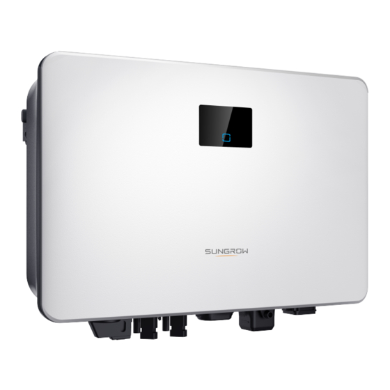
2 Product Description User Manual Description Item Note Utility grid TT,TN-C,TN-S, TN-C-S. House loads that consume electricity. Loads The following figure shows the common grid configurations. Product Introduction Model Description The model description is as follows (take SG3.0RS-S as an example): Appearance The following figure shows the dimensions of the inverter. - Page 17 User Manual 2 Product Description figure 2-2 Inverter Appearance Description Name Information about COM2 pin definition, supported DRM Label modes, etc. Complement to the included wall mounting bracket for hang- Hanger ing the inverter. The LED screen indicates the running information and the LED pannel LED indicator indicates the working state of the inverter.
-
Page 18: Symbols On The Product
2 Product Description User Manual figure 2-3 Dimensions of the Inverter Inverter Model W (mm) H (mm) D (mm) SG2.0RS-S, SG2.5RS-S, SG3.0RS-S SG3.0RS, SG3.6RS, SG4.0RS, SG5.0RS, SG6.0RS Symbols on the Product Symbol Explanation Parameters on the DC side. Parameters on the AC on-grid side. -
Page 19: Led Panel
User Manual 2 Product Description Symbol Explanation Read the user manual before maintenance! Burn danger due to the hot surface that may exceed 60℃. Danger to life due to high voltages! Do not touch live parts for 10 minutes after disconnection from the power sources. -
Page 20: Circuit Diagram
2 Product Description User Manual table 2-1 State description of the LED indicator LED color State Definition The inverter is operating normally. The inverter is at standby or startup state (not Flashing feeding power into the grid). Blue A system fault has occured. Both the AC and DC sides are powered down. -
Page 21: Function Description
After communication connection is established, users can view inverter information, op- erational data and can set inverter parameters through the iSolarCloud. It is recommended to use the communication module from SUNGROW. Using a device from other companies may lead to communication failure or other un- expected damage. - Page 22 2 Product Description User Manual DRM ("AU"/"NZ") The DRM function is only applicable to a single inverter. The inverter provides terminals for connecting to a Demand Response Enabling Device (DRED). After the connection, the DRED asserts demand response modes (DRMs). The in- verter detects and initiates a response to all supported demand response modes listed in the following table.
- Page 23 User Manual 2 Product Description AFCI Function(Optional) • AFCI activation This function can be enabled to detect whether arc occurs in the DC circuit of the inverter. • AFCI self-test This function is intended to detect whether the AFCI function of the inverter is normal. The arc detection function meets the standard requirements, please test under the working conditions as required by the standard.
-
Page 24: Unpacking And Storage
• Check the inner contents for damage after unpacking. Contact SUNGROW or the transport company in case of any damage or incompleteness, and provide photos to facilitate services. Do not dispose of the original packing case. It is recommended to store the device in the original packing case when the product is decommissioned. - Page 25 User Manual 3 Unpacking and Storage • Do not place the inverter in places with items that may affect or damage the inverter. • Store the inverter in a clean and dry place to prevent dust and water vapor from eroding. •...
-
Page 26: Mechanical Mounting
Mechanical Mounting Respect all local standards and requirements during mechanical installation. Safety during Mounting Make sure there is no electrical connection before installation. Before drilling, avoid the water and electricity wiring in the wall. Poor installation environment will affect system performance! •... -
Page 27: Environment Requirements
User Manual 4 Mechanical Mounting 4.2.1 Environment Requirements • The installation environment must be free of inflammable or explosive materials. • The location should be not accessible to children. • The ambient temperature and relative humidity must meet the following requirements. •... -
Page 28: Clearance Requirements
4 Mechanical Mounting User Manual 4.2.4 Clearance Requirements Reserve enough clearance around the inverter to ensure sufficient space for heat dissipation. Install the inverter at an appropriate height for ease of viewing the screen and LED indicator and operating switch(es). Installation Tools Installation tools include but are not limited to the following recommended ones. - Page 29 User Manual 4 Mechanical Mounting table 4-1 Tool specification Goggles Earplugs Dust mask Protective gloves Insulated shoes Utility knife Marker Wrist strap Wire cutter Wire stripper Hydraulic plier RJ45 crimping tool MC4 terminal Tube terminal Electric screwdriver Slotted screwdriver crimping tool (0.5 (M4, M6) crimping tool (4 (M2)
-
Page 30: Moving The Inverter
4 Mechanical Mounting User Manual Heat gun Wrench (33 mm, 35 MC4 terminal Multimeter (≥ 600 wrench Vdc) Rubber mallet Hammer drill (φ10) Moving the Inverter Before installation, remove the inverter from the packing case and move it to the installation site. - Page 31 * The image shown here is for reference only. The actual product received may differ. Inverter Model L1 (mm) L2 (mm) H (mm) SG2.0RS-S, SG2.5RS-S, SG3.0RS-S SG3.0RS, SG3.6RS, SG4.0RS, SG5.0RS, SG6.0RS step 2 Place the expansion tubes into the holes. Then secure the wall-mounting bracket to the wall firmly with the expansion bolt sets.
- Page 32 4 Mechanical Mounting User Manual step 3 Lift the inverter and slide it down along the wall-mounting bracket to make sure they match perfectly. Use two screw sets to lock both left and right sides. - - End...
-
Page 33: Electrical Connection
Electrical Connection Safety Instructions The PV string will generate lethal high voltage when exposed to sunlight. • Operators must wear proper personal protective equipment during electrical connections. • Must ensure that cables are voltage-free with a measuring instrument before touching DC cables. •... -
Page 34: Terminal Description
5 Electrical Connection User Manual All vacant terminals must be covered with waterproof covers to prevent affecting the protection rating. When the wiring is completed, seal the gap of cable inlet and outlet holes with fire- proof / waterproof materials such as fireproof mud to prevent foreign matter or moisture from entering and affecting the long-term normal operation of the inverter. -
Page 35: Electrical Connection Overview
User Manual 5 Electrical Connection Decisive Volt- Description Name Classification Communication connection for COM2 RS485, DRM and smart energy DVC-A meter. AC terminal to connect to the grid. GRID DVC-C Additional grounding terminal. Not applicable The pin definition of COM2 terminal is shown in the following label. figure 5-2 Label of COM2 Terminal table 5-2 Label Description of COM2 Terminal Description... -
Page 36: External Grounding Connection
5 Electrical Connection User Manual (A) PV string (B) Inverter (C) Loads (D) Grid (E) Smart energy meter (optional) (F) AC circuit breaker (G) External device table 5-3 Cable Requirements Wire Conductor Type Cable Cable Diameter Cross-section Single or multi-core copper wire comply- DC cable 6 mm–9 mm... -
Page 37: External Grounding Requirements
The ground connection of this additional grounding terminal cannot replace the connection of the PE terminal of the AC cable. Make sure those terminals are both grounded reliably. SUNGROW shall not be held liable for any damage caused by the violation. -
Page 38: Ac Cable Connection
AC Circuit Breaker An independent two-pole circuit breaker must be installed on the output side of the inverter to ensure safe disconnection from the grid. The recommended specifications are as follows. Recommended Specification Inverter Model SG2.0RS-S/SG2.5RS-S/SG3.0RS-S 25 A SG3.0RS/SG3.6RS/SG4.0RS/SG5.0RS 32 A SG6.0RS... -
Page 39: Assembling The Ac Connector
User Manual 5 Electrical Connection AC circuit breakers should be installed on the output side of the inverter and the grid side to ensure safe disconnection from the grid. • Determine whether an AC circuit breaker with greater overcurrent capacity is re- quired based on actual conditions. - Page 40 5 Electrical Connection User Manual step 3 Remove the cable jacket by less than 45 mm, and strip the wire insulation by 12 mm–16 mm. step 4 Open the clamp on the spring-loaded terminal and fully insert the wires into the correspond- ing holes.
-
Page 41: Installing The Ac Connector
User Manual 5 Electrical Connection step 5 Ensure that the wires are securely in place by slightly pulling them. Tighten the swivel nut to the housing. - - End 5.5.3 Installing the AC Connector High voltage may be present in inverter! Ensure all cables are voltage-free before electrical connection. -
Page 42: Dc Cable Connection
600 V. The inverter returns to running state once the voltage returns to the MPPT operating voltage range, namely, 40 V to 560 V. 5.6.1 PV Input Configuration • The inverters SG2.0RS-S / SG2.5RS-S / SG3.0RS-S have one PV input with one MPP tracker. -
Page 43: Assembling The Pv Connectors
User Manual 5 Electrical Connection • The inverters SG3.0RS / SG3.6RS / SG4.0RS / SG5.0RS / SG6.0RS have two PV in- puts, each with independent MPP tracker. Each DC input area can operate independently. • The PV strings to the same DC input area should have the same type, the same number of PV panels, identical tilt and identical orientation for maximum power. -
Page 44: Installing The Pv Connectors
5 Electrical Connection User Manual step 2 Assemble the cable ends with the crimping pliers. 1: Positive crimp contact 2: Negative crimp contact step 3 Lead the cable through cable gland, and insert the crimp contact into the insulator until it snaps into place. -
Page 45: Winet-S Connection
User Manual 5 Electrical Connection step 2 Check the cable connection of the PV string for polarity correctness and ensure that the open circuit voltage in any case does not exceed the inverter input limit of 600 V. step 3 Connect the PV connectors to corresponding terminals until there is an audible click. step 4 Seal the unused PV terminals with the terminal caps. -
Page 46: Ethernet Communication
5 Electrical Connection User Manual For details, see the quick guide for the WiNet-S module. Scan the following QR code for the quick guide. 5.7.1 Ethernet Communication step 1 (Optional) Strip the insulation layer of the communication cable with an Ethernet wire strip- per, and lead the corresponding signal cables out. - Page 47 User Manual 5 Electrical Connection step 4 Thread the network cable through the swivel nut and gasket. Afterwards, route the cable into the opening of the sealing. Finally, insert the cable through the housing. step 5 Insert the RJ45 plug into the front plug connector until there is an audible click and tighten the housing.
-
Page 48: Wlan Communication
5 Electrical Connection User Manual step 7 Slightly shake it by hand to determine whether it is installed firmly. - - End 5.7.2 WLAN Communication step 1 Remove the waterproof lid from the COM1 terminal. step 2 Install the module. Slightly shake it by hand to determine whether it is installed firmly, as shown below. - Page 49 User Manual 5 Electrical Connection step 3 Remove the cable jacket and strip the wire insulation. step 4 (Optional) When using a multi-core multi-strand wire cable, connect the wire head to the cord end terminal. In case of single-strand copper wire, skip this step. step 5 Plug the wires into the corresponding terminals as shown in the following figure.
-
Page 50: Drm Connection
5 Electrical Connection User Manual step 6 Insert the terminal plug into the COM2 terminal at the bottom side of the inverter and then in- stall the housing. step 7 Slightly pull out the cable and then fasten the swivel nut. Lock the connector with the screw. - - End DRM Connection In Australia and New Zealand, the inverter supports DRM0 as specified in the standard AS/... - Page 51 User Manual 5 Electrical Connection step 2 Remove the seal and lead the cable through the cable gland. step 3 Remove the cable jacket and strip the wire insulation. step 4 (Optional) When using a multi-core multi-strand wire cable, connect the wire head to the cord end terminal.
- Page 52 5 Electrical Connection User Manual step 5 Plug the wires into the corresponding terminals as shown in the following figure. Ensure that the wires are securely in place by slightly pulling them. step 6 Insert the terminal plug into the COM2 terminal at the bottom side of the inverter and then in- stall the housing.
- Page 53 User Manual 5 Electrical Connection - - End...
-
Page 54: Commissioning
Commissioning Inspection before Commissioning Check the following items before starting the inverter: • All equipment has been reliably installed. • DC switch(es) and AC circuit breaker are in the "OFF" position. • The ground cable is properly and reliably connected. •... -
Page 55: Creating A Plant
"7.3 Account Registration". If you have got the account and password from the distributor/installer or SUNGROW, skip this step. step 3 Download the firmware package to the mobile device in advance. Refer to “Firmware Upa- date”. This is to avoid download failure due to poor on-site network signal. - Page 56 6 Commissioning User Manual figure 6-3 Selecting Plant/Inverter Type step 5 Scan the QR code on the communication device or manually enter the serial number of the communication device. Tap Next after the QR code is identified or the serial number entered is correct and then tap CONFIRM.
-
Page 57: Initializing The Device
User Manual 6 Commissioning blinks quickly when this mode is turned on. Return to the App and the screen displays suc- cessful connection to the inverter WLAN. Tap NEXT. figure 6-6 Turn on EasyConnect Mode The EasyConnect mode can be used only when the router is 2.4 GHz. If the EasyConnect mode fails, refer to the WiNet-S quick guide for the instructions of other modes. - Page 58 6 Commissioning User Manual figure 6-8 Upgrade Reminder step 2 After download, it would take around 15 minutes to update. After successful upgrade, the screen will show the version numbers before and after the upgrade as well as the upgrade time.
- Page 59 User Manual 6 Commissioning Country/Region Setting Spain Spain Australia ("AU") Australia New Zealand ("NZ") New Zealand Countries not listed above Other 50Hz or Other 60Hz The parameter Country/Region must be set to the country (region) where the inver- ter is installed at. Otherwise, the inverter may report errors. step 4 When the country is set to Australia, additionally set the applicable network service provider and then the grid type.
- Page 60 6 Commissioning User Manual Network Service Provider Grid Type AS/NZS 4777.2:2020 Australia C • STNW1170: single-phase < 10 kVA & ENERGEX & Ergon Energy three-phase < 30 kVA • STNW1174: 30 kVA < P ≤ 1500 kVA • ≤ 10 kVA per phase (or 30 kVA per three phase) Jemena •...
-
Page 61: Configuring The Plant
User Manual 6 Commissioning figure 6-10 Initializing Parameters - - End Configuring the Plant The inverter is successfully added to the plant and initialized. Refer to the guidance in pre- vious sections. The distributor/installer who creates a plant for the end user needs to get the end user's e- mail address. - Page 62 6 Commissioning User Manual figure 6-12 Entering Plant Information step 3 (Optional) Fill in the tariff information. The electricity price can be set to a specific value or Time-of-Use tariff. figure 6-13 Entering Tariff Information step 4 Fill in the end user's e-mail address. The first time you fill in the end user's e-mail address, the system will create an account for the end user and send an email to the end user.
- Page 63 User Manual 6 Commissioning figure 6-14 Entering Owner's e-mail step 5 Tap NEXT to wait for the inverter to connect to the iSolarCloud. figure 6-15 Configuration Completed step 6 (Optional) Tab View live data for the device, tick Inverter or Total Plant Devices and tab ALL PLANTS OPEN.
- Page 64 User Manual figure 6-16 Live Data View Function Setting Contact Sungrow service to enable live data function of devices. Once enabled, live data function is available for 3 hours per day by default. To make it available for 24 hours, contact SUNGROW.
-
Page 65: Isolarcloud App
App. * To achieve direct login via WLAN, the wireless communication module developed and manufactured by SUNGROW is required. The iSolarCloud App can also establish communi- cation connection to the inverter via Ethernet connection. -
Page 66: Account Registration
7 iSolarCloud App User Manual Account Registration The account distinguishes two user groups, end user and distributor/installer. • The end user can view plant information, create plants, set parameters, share plants, etc. • The distributor/installer can help the end user to create plants, manage, install, or main- tain plants, and manage users and organizations. -
Page 67: Login
User Manual 7 iSolarCloud App step 4 Fill in the registration information, including email, verification code, password and affirm- ance and country (region). The distributor/installer has the permission to fill in the company name and the code of upper level distributor/installer. The code of upper level distributor/installer can be obtained from the upper level distributor/installer. - Page 68 7 iSolarCloud App User Manual figure 7-1 Enabling the WLAN Hotspot step 2 Connect the mobile phone to the WLAN network named as "SG-xxxxxxxxxxx" (xxxxxxxxxxx is the serial number indicated on the side of the communication module). step 3 Open the App to enter the login screen. Tap Local Access to enter the next screen. step 4 Select WLAN and select the device (SN), then enter the password and tap LOGIN.
-
Page 69: Initial Settings
User Manual 7 iSolarCloud App The "Country/Region" must be set to the country where the inverter is installed at. Otherwise, the inverter may report errors. figure 7-3 WLAN Local Access step 6 After finishing the settings, tap TUNR ON DEVICE at the upper right corner and the device will be initialized. -
Page 70: Function Overview
7 iSolarCloud App User Manual The actual initializing procedure may differ due to different countries. Please fol- low the actual App guidance. For some countries, you should initialize parameters according to local grid re- quirements. For details, see "6.5 Initializing the Device". -
Page 71: Home
User Manual 7 iSolarCloud App figure 7-4 App Key Function Menu Home Home page of the App is shown in the following figure. -
Page 72: Run Information
7 iSolarCloud App User Manual figure 7-5 Home table 7-1 Home Page Description Description Name Present operation state of the inverter Inverter state Shows the PV power generation power, feed-in power, etc. Energy flow The line with an arrow indicates energy flow between con- chart nected devices, and the arrow pointing indicates energy flow direction. -
Page 73: Records
User Manual 7 iSolarCloud App table 7-2 Description of Run Information Description Item Shows voltage and current of every PV string. PV information Shows basic information such as running state, on-grid running time, Inverter negative voltage to grid, bus voltage, internal air temperature, inver- information ter efficiency, etc. - Page 74 7 iSolarCloud App User Manual figure 7-7 Chart The App displays power generation records in a variety of forms, including daily power gen- eration graph, monthly power generation histogram, annual power generation histogram and total power generation histogram. table 7-3 Description of Power Curve Description Item Daily...
- Page 75 User Manual 7 iSolarCloud App figure 7-8 Fault Alarm Record Click to select a time segment and view corresponding records. Select one of the records in the list and click the record, to view the detailed fault info as shown in following figure. figure 7-9 Detailed Fault Alarm Information Event Record Tap Event Record to enter the screen, as shown in the following figure.
-
Page 76: More
7 iSolarCloud App User Manual figure 7-10 Event Record Click to select a time segment and view corresponding records. 7.10 More Tap More on the navigation bar to enter the corresponding screen, as shown in the following figure. figure 7-11 More In addition to viewing the WLAN configuration and App software version, the More screen supports the following operations: •... -
Page 77: System Parameters
User Manual 7 iSolarCloud App 7.10.1 System Parameters Tap Settings→System Parameters to enter the corresponding screen, as shown in the fol- lowing figure. figure 7-12 System Parameters * The image shown here is for reference only. Boot/Shutdown Tap Boot/Shutdown to send the boot/shutdown instruction to the inverter. For Australia and New Zealand, when the DRM state is DRM0, the "Boot"... -
Page 78: Power Regulation Parameters
7 iSolarCloud App User Manual figure 7-14 PID Setting table 7-4 PID Parameter Description Description Parameter Set enabling/disabling of the PID night recovery function. PID night PID Recovery recovery function operates between 22:00 pm and 5:00 am by default. AFCI Parameters(Optional) Tap Settings→Operation Parameters→AFCI Parameters to enter the corresponding screen, on which you can set "AFCI Parameters". - Page 79 User Manual 7 iSolarCloud App figure 7-16 Active Power Regulation table 7-5 Description of Active Power Regulation Parameters Description Range Parameter Active Power Soft Start Switch for activating/deactivating the function On/Off after Fault of active power soft start after a fault occurs Active Power Soft Start The soft start time required for raising active 1 s–1200 s...
- Page 80 7 iSolarCloud App User Manual figure 7-17 Reactive Power Regulation table 7-6 Description of Reactive Power Regulation Parameters Description Range Parameter Reactive Power Set- Switch for activating/deactivating the function On/Off ting Persistence of reactive power setting persistence Reactive Power Regu- Off/PF/Qt/Q Off/PF/Qt/Q(P)/Q(U) lation Mode...
- Page 81 User Manual 7 iSolarCloud App table 7-7 "Q(P)" Mode Parameters Explanation Parameter Explanation Range Q(P) Curve Select corresponding curve according to local A, B, C regulations QP_P1 Output power at point P1 on the Q(P) mode curve 0.0 %–100.0 % (in %) QP_P2 Output power at point P2 on the Q(P) mode curve...
- Page 82 7 iSolarCloud App User Manual The reactive power output of the inverter varies in response to the grid voltage. table 7-8 "Q(U)" Mode Parameter Explanation Explanation Range Parameter Select corresponding curve according to local Q(U) curve A, B, C regulations Hysteresis Voltage hysteresis ratio on the Q(U) mode curve 0.0 %–5.0 %...
-
Page 83: Communication Parameters
User Manual 7 iSolarCloud App figure 7-19 Reactive Power Regulation Curve in Q(U) Curve 7.10.4 Communication Parameters Tap Settings→Communication Parameters→Serial Port Parameters to enter the corre- sponding interface, as shown in the following figure. figure 7-20 Serial Port Parameters table 7-9 Serial Port Parameters Range Parameter Device Address... -
Page 84: Firmware Update
7 iSolarCloud App User Manual figure 7-21 MPLC Parameters table 7-10 MPLC Parameters Range Parameter Band Num Band1, Band2 Array ID 1–255 Winding ID 1–10 7.10.5 Firmware Update To avoid download failure due to poor on-site network signal, it is recommended to download the firmware package to the mobile device in advance. -
Page 85: Auto-Test
User Manual 7 iSolarCloud App step 9 Wait for the file to be uploaded. When the upgrade is finished, the interface will inform you of the upgrade completion. Tap Complete to end the upgrade. - - End 7.10.6 Auto-test Tap Auto-test to enter the corresponding screen, as shown in the following figure. figure 7-22 Auto-test Launch Auto-test Tap Launch Auto-test carry out an auto-test. - Page 86 7 iSolarCloud App User Manual figure 7-23 Auto-test Result Clear Auto-test Fault Tap Clear Auto-test Fault→CONFIRM to clear the auto-test fault. figure 7-24 Clear Auto-test Fault...
-
Page 87: System Decommissioning
System Decommissioning Disconnecting the Inverter Risk of burns due to hot components! Even if the inverter is shut down, it may still be hot and cause burns. Wear protec- tive gloves before operating the inverter after it cools down. For maintenance or other service work, the inverter must be switched off. Proceed as follows to disconnect the inverter from the AC and DC power sources. -
Page 88: Disposal Of The Inverter
8 System Decommissioning User Manual step 2 Refer to"4 Mechanical Mounting", to dismantle the inverter in reverse steps. step 3 If necessary, remove the wall-mounting bracket from the wall. step 4 If the inverter will be used again in the future, please refer to "3.2 Inverter Storage"... -
Page 89: Troubleshooting And Maintenance
Troubleshooting and Maintenance Troubleshooting Once the inverter fails, the fault information can be displayed on the App interface. If the in- verter is equipped with an LCD screen, the fault information can be viewed on it. The fault codes and troubleshooting methods of all PV inverters are detailed in the table be- low. - Page 90 App or the LCD. Modify the overvoltage protection values with the consent of the local electric power operator. 3. Contact Sungrow Customer Service if the preceding causes are ruled out and the fault persists. Generally, the inverter will be reconnected to the grid after the grid returns to normal.
- Page 91 Grid Underfrequency 2. Check whether the protection parameters are appropriately set via the App or the LCD. 3. Contact Sungrow Customer Service if the preceding causes are ruled out and the fault persists. Generally, the inverter will be reconnected to the grid after the grid returns to normal.
- Page 92 1. Measure the actual grid, and contact the lo- cal electric power company for solutions if the Grid Abnormal grid parameter exceeds the set range. 2. Contact Sungrow Customer Service if the preceding causes are ruled out and the fault persists. Generally, the inverter will be reconnected to the grid after the grid returns to normal.
- Page 93 If so, disconnect the DC switch and adjust the polarity when the string current drops below 0.5 A. 2. Contact Sungrow Customer Service if the 532-547, PV Reverse Connection preceding causes are ruled out and the alarm...
- Page 94 Resistance layer. 3. If the cable is normal and the fault occurs on rainy days, check it again when the weath- er turns fine. 4. Contact Sungrow Customer Service if the preceding causes are ruled out and the fault persists.
- Page 95 2. Check whether the insulation between the Grounding Cable Fault ground cable and the live wire is normal. 3. Contact Sungrow Customer Service if the preceding causes are ruled out and the fault persists. 1. Disconnect the DC power supply, and...
- Page 96 2. Reconnect the communication cable of the Inverter Parallel Com- meter. munication Alarm 3. Contact Sungrow Customer Service if the preceding causes are ruled out and the alarm persists. 7, 11, 16, 19–25, 30– 34, 36, 38, 40–42, 44–...
- Page 97 432–434, abnormalities, and take corresponding correc- 500–513, tive measures when necessary. 515–518, If the fault persists, please contact Sungrow 900, 901, Power Customer Service. 910, 911 1. Check whether the corresponding string is of reverse polarity. If so, disconnect the DC switch and adjust the polarity when the string current drops below 0.5 A.
-
Page 98: Maintenance
364-395 voltage Fault later to restart the inverter. If the fault still ex- ists, contact Sungrow Customer Service. 1. Check whether the number of PV modules of the corresponding string is less than other strings. If so, disconnect the DC switch and adjust the PV module configuration when the string current drops below 0.5 A. -
Page 99: Routine Maintenance
To avoid the risk of electric shock, do not perform any other maintenance opera- tions beyond this manual. If necessary, contact SUNGROW for maintenance. Oth- erwise, the losses caused is not covered by the warranty. -
Page 100: Appendix
10 Appendix 10.1 Technical Data Parameter SG2.0RS-S SG2.5RS-S SG3.0RS-S Input (DC) Recommended max. PV in- 3.0 kWp 3.75 kWp 4.5 kWp put power Max. PV input voltage 600 V Min. operating PV voltage / 40 V / 50 V Start-up input voltage... - Page 101 User Manual 10 Appendix Parameter SG2.0RS-S SG2.5RS-S SG3.0RS-S Efficiency Max. efficiency / European 97.8 % / 96.9 % 97.8 % / 97.2 % 97.8 % / 97.3 % efficiency Protection Grid monitoring DC reverse polarity protection AC short circuit protection...
- Page 102 10 Appendix User Manual Parameter SG3.0RS SG3.6RS SG4.0RS Input (DC) Recommended max. PV in- 4.5 kWp 5.4 kWp 6 kWp put power Max. PV input voltage 600 V Min. operating PV voltage / 40 V / 50 V Start-up input voltage Rated PV input voltage 360 V MPP voltage range...
- Page 103 User Manual 10 Appendix Parameter SG3.0RS SG3.6RS SG4.0RS DC reverse polarity protection AC short circuit protection Leakage current protection Surge Protection DC type II / AC type II Optional DC switch PV string current monitoring Arc fault circuit interrupter Optional (AFCI) PID recovery function General Data...
- Page 104 10 Appendix User Manual Parameter SG5.0RS SG6.0RS Min. operating PV voltage / Start-up 40 V / 50 V input voltage Rated PV input voltage 360 V MPP voltage range 40 V – 560 V No. of MPPTs Default No. of PV strings per MPPT Max.
-
Page 105: Quality Assurance
* The inverter enters standby state when the input voltage ranges between 560 V and 600 V. ** This function is only available for non-AU versions. 10.2 Quality Assurance When product faults occur during the warranty period, SUNGROW will provide free service or replace the product with a new one. Evidence During the warranty period, the customer shall provide the product purchase invoice and date. -
Page 106: Contact Information
10 Appendix User Manual Exclusion of Liability In the following circumstances, SUNGROW has the right to refuse to honor the quality guarantee: • The free warranty period for the whole machine/components has expired. • The device is damaged during transport.
Need help?
Do you have a question about the SG2.0RS-S and is the answer not in the manual?
Questions and answers