Table of Contents
Advertisement
Quick Links
User Manual
3-Phase PV Grid-Connected Inverter
SG3.0RT / SG4.0RT / SG5.0RT / SG6.0RT / SG7.0RT /
SG8.0RT / SG10RT / SG12RT / SG15RT / SG17RT /
SG20RT /SG5.0RT-P2 / SG6.0RT-P2 / SG7.0RT-P2 /
SG8.0RT-P2 / SG10RT-P2 / SG12RT-P2 / SG15RT-P2 /
SG17RT-P2 / SG20RT-P2
SG3.0RT /
SG4.0RT / SG5.0RT / SG6.0RT /
SG7.0RT / SG8.0RT / SG10RT /
SG12RT / SG15RT / SG17RT /
P2 / SG12RT-P2 / SG15RT-P2 /
Grid-Connected InverterUser
SG3.0-20RT_SG5.0-20RT-P2-UEN-Ver11-202304
Advertisement
Table of Contents

Related Manuals for Sungrow SG5.0RT-P2


Summary of Contents for Sungrow SG5.0RT-P2
- Page 1 3-Phase PV Grid-Connected Inverter SG3.0RT / SG4.0RT / SG5.0RT / SG6.0RT / SG7.0RT / SG8.0RT / SG10RT / SG12RT / SG15RT / SG17RT / SG20RT /SG5.0RT-P2 / SG6.0RT-P2 / SG7.0RT-P2 / SG8.0RT-P2 / SG10RT-P2 / SG12RT-P2 / SG15RT-P2 / SG17RT-P2 / SG20RT-P2 SG3.0RT /...
-
Page 3: All Rights Reserved
Software Licenses • It is prohibited to use data contained in firmware or software developed by SUNGROW, in part or in full, for commercial purposes by any means. • It is prohibited to perform reverse engineering, cracking, or any other operations that... -
Page 4: About This Manual
• SG6.0RT • SG7.0RT • SG8.0RT • SG10RT • SG12RT • SG15RT • SG17RT • SG20RT • SG5.0RT-P2 • SG6.0RT-P2 • SG7.0RT-P2 • SG8.0RT-P2 • SG10RT-P2 • SG12RT-P2 • SG15RT-P2 • SG17RT-P2 • SG20RT-P2 It will be referred to as "inverter" hereinafter unless otherwise specified. - Page 5 Please read this manual carefully before using the product and keep it properly at a place for easy access. All contents, pictures, marks, and symbols in this manual are owned by SUNGROW. No part of this document may be reprinted by the non-internal staff of SUNGROW without written authorization.
- Page 6 “NOTE” indicates additional information, emphasized contents or tips that may be helpful, e.g., to help you solve problems or save time.
-
Page 7: Table Of Contents
Contents All Rights Reserved .....................I About This Manual......................II 1 Safety Instructions ....................1 1.1 Unpacking and Inspection ................2 1.2 Installation Safety ...................2 1.3 Electrical Connection Safety................3 1.4 Operation Safety ....................4 1.5 Maintenance Safety ..................5 1.6 Disposal Safety ....................6 2 Product Description ..................7 2.1 System Introduction ..................7 2.2 Product Introduction..................9... - Page 8 5.1 Safety Instructions ..................29 5.2 Terminal Description ..................31 5.3 Electrical Connection Overview ..............32 5.4 External Protective Grounding Connection .............34 5.4.1 External Protective Grounding Requirements ........35 5.4.2 Connection Procedure.................35 5.5 AC Cable Connection ...................37 5.5.1 AC Side Requirements ................37 5.5.2 Assembling the AC Connector (< 15 kW) ..........38 5.5.3 Installing the AC Connector (<...
- Page 9 7 iSolarCloud App ....................84 7.1 Brief Introduction ..................84 7.2 Installing App ....................84 7.3 Account Registration..................85 7.4 Login ......................86 7.4.1 Requirements ..................86 7.4.2 Login Procedure .................86 7.5 Initial Settings....................88 7.6 Function Overview..................89 7.7 Home ......................90 7.8 Run Information....................91 7.9 Records .......................91 7.10 More ......................94 7.10.1 System Parameters................95 7.10.2 Operation Parameters ...............95...
-
Page 11: Safety Instructions
Perform operations considering ac- tual onsite conditions. • SUNGROW shall not be held liable for any damage caused by violation of gen- eral safety operation requirements, general safety standards, or any safety in- struction in this manual. -
Page 12: Unpacking And Inspection
If there are problems with the above inspection items, do not install the device and contact your distributor first. If the problem persists, con- tact SUNGROW in time. Installation Safety •... -
Page 13: Electrical Connection Safety
User Manual 1 Safety Instructions Electrical Connection Safety • Before electrical connections, please make sure that the inverter is not dam- aged, otherwise it may cause danger! • Before electrical connections, please make sure that the inverter switch and all switches connected to the inverter are set to "OFF", otherwise electric shock may occur! The PV string will generate lethal high voltage when exposed to sunlight. -
Page 14: Operation Safety
1 Safety Instructions User Manual • Check the positive and negative polarity of the PV strings, and connect the PV connectors to corresponding terminals only after ensuring polarity correctness. • During the installation and operation of the inverter, please ensure that the posi- tive or negative poles of PV strings do not short-circuit to the ground. -
Page 15: Maintenance Safety
To avoid the risk of electric shock, do not perform any other maintenance opera- tions beyond those described in this manual. If necessary, contact your distributor first. If the problem persists, contact SUNGROW. Otherwise, the losses caused is not covered by the warranty. -
Page 16: Disposal Safety
1 Safety Instructions User Manual • If the paint on the inverter enclosure falls or rusts, repair it in time. Otherwise, the inverter performance may be affected. • Do not use cleaning agents to clean the inverter. Otherwise, the inverter may be damaged, and the loss caused is not covered by the warranty. -
Page 17: Product Description
Product Description System Introduction The inverter is a transformerless 3-phase PV grid-connected inverter. As an integral compo- nent in the PV power system, the inverter is designed to convert the direct current power generated from the PV modules into grid-compatible AC current and feeds the AC current to the utility grid. - Page 18 Note Compatible with monocrystalline silicon, polycrystalline silicon, PV strings and thin-film modules without grounding SG3.0RT, SG4.0RT, SG5.0RT, SG6.0RT, SG7.0RT, SG8.0RT, SG10RT, SG12RT, SG15RT, SG17RT, SG20RT, SG5.0RT-P2, Inverter SG6.0RT-P2, SG7.0RT-P2, SG8.0RT-P2, SG10RT-P2, SG12RT-P2, SG15RT-P2, SG17RT-P2, SG20RT-P2 Metering device Meter cupboard with power distribution system...
-
Page 19: Product Introduction
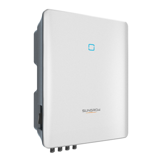
Please contact your local sales staff to confirm that the optimizer is available for sale in your territory. SP600S optimizer is not compatible with third-party products. It is recommended to use the optimizer produced by SUNGROW. Optimizers from third-party manufacturers may fail or even cause unknown losses. - Page 20 2 Product Description User Manual figure 2-2 Inverter Appearance Description Name To clearly identify the product, including device model, S/N, Nameplate important specifications, marks of certification institutions, etc. To indicate the current working state of the inverter. LED indicator Complement to the included wall-mounting bracket for hang- Hanger ing the inverter.
-
Page 21: Symbols On Product
User Manual 2 Product Description figure 2-3 Dimensions of the Inverter(in mm) Symbols on Product Symbol Explanation Regulatory compliance mark. TÜV mark of conformity. CE mark of conformity. EU/EEA Importer. UKCA mark of conformity. Do not dispose of the inverter together with household waste. The inverter does not have a transformer. -
Page 22: Led Indicator
2 Product Description User Manual Symbol Explanation Danger to life due to high voltages! Do not touch live parts for 10 minutes after disconnection from the power sources. Only qualified personnel can open and maintain the inverter. External protective grounding terminal. * The table shown here is for reference only. -
Page 23: Function Description
User Manual 2 Product Description figure 2-4 Circuit Diagram (SG5.0RT for example) • DC Switches can safely disconnect the PV input when necessary to ensure the safe op- eration of the inverter and the safety of personnel. • The DC SPD provides a discharge circuit for the DC side overvoltage to prevent it from damaging the internal circuits of the inverter. - Page 24 After communication connection is established, users can view inverter information, op- erational data and can set inverter parameters through the iSolarCloud. It is recommended to use the communication module from SUNGROW. Using a device from other companies may lead to communication failure or other un- expected damage.
- Page 25 User Manual 2 Product Description • For negative voltage scheme, after the PID function is enabled, the voltage to ground of all PV strings is lower than 0, and therefore the PV string-to-ground voltage is a negative value. • Before enabling the PID recovery function, make sure the voltage polarity of the PV modules to ground meets requirement.
- Page 26 2 Product Description User Manual meet the requirements of CEI0-21 to protect the grid from abnormality after the inverter is operational. AFCI Function(Optional) • AFCI activation This function can be enabled to detect whether serial fault arc occurs in the loop between PV array and inverter.
- Page 27 User Manual 2 Product Description Plant ≤ 11.08 kVA > 11.08 kVA Size 253 V / < 603 253 V / < 603 253 V / < 603 253 V / < 603 253 V / <603 59.S1 264.5 V / 0.2 264.5 V / 0.2 264.5 V / 0.2 264.5 V / 0.2...
-
Page 28: Unpacking And Storage
• Check the inner contents for damage after unpacking. Contact SUNGROW or the transport company in case of any damage or incompleteness, and provide photos to facilitate services. Do not dispose of the original packing case. It is recommended to store the device in the original packing case when the product is decommissioned. - Page 29 User Manual 3 Unpacking and Storage • Do not place the inverter in places with items that may affect or damage the inverter. • Store the inverter in a clean and dry place to prevent dust and water vapor from eroding. •...
-
Page 30: Mechanical Mounting
Mechanical Mounting Respect all local standards and requirements during mechanical installation. Safety During Mounting Make sure there is no electrical connection before installation. Before drilling, avoid the water and electricity wiring in the wall. Poor installation environment will affect system performance! •... -
Page 31: Location Requirements
User Manual 4 Mechanical Mounting Location Requirements To a large extent, a proper installation location ensures safe operation, service life, and per- formance of the inverter. • The inverter with protection rating IP65 can be installed both indoors and outdoors. •... -
Page 32: Angle Requirements
4 Mechanical Mounting User Manual 4.2.3 Angle Requirements Install the inverter vertically. Never install the inverter horizontally, or at forward/backward tilted, side tilted, or upside down. 4.2.4 Clearance Requirements Reserve enough clearance around the inverter to ensure sufficient space for heat dissipation. -
Page 33: Installation Tools
User Manual 4 Mechanical Mounting In case of multiple inverters, reserve specific clearance between the inverters. Install the inverter at an appropriate height for ease of viewing LED indicator and operating switch(es). Installation Tools Installation tools include but are not limited to the following recommended ones. If necessary, use other auxiliary tools on site. - Page 34 4 Mechanical Mounting User Manual Safety shoes Utility knife Marker Anti-static wrist strap Wire cutter Wire stripper Hydraulic pliers Rubber mallet Hammer drill (φ10) Phillips screwdriver Electric screwdriver Open-end wrench (M3, M4, M6) (M3, M4, M6) (30 mm, 35 mm, 46 RJ45 crimping tool Vacuum cleaner Measuring tape...
-
Page 35: Moving The Inverter
User Manual 4 Mechanical Mounting Slotted screwdriver Connector wrench (M2) Moving the Inverter Before installation, remove the inverter from the packing case and move it to the installation site. Follow the instructions below as you move the inverter: • Always be aware of the weight of the inverter. •... - Page 36 4 Mechanical Mounting User Manual (1) Self-tapping (2) Expansion tube (3) Fender washer (4) Spring washer screw M6 step 1 Place the wall-mounting bracket to a proper position on the wall. Observe the level on the bracket and adjust until the bubble is in the middle position. Mark the positions and drill the holes.
-
Page 37: Installing Optimizer(Optional)
User Manual 4 Mechanical Mounting - - End Installing Optimizer(Optional) step 1 As shown in the figure below, clamp the optimizer parallel to the back of the PV module by clips. - Page 38 4 Mechanical Mounting User Manual • Please ensure that the optimizer is installed facing the back of the module. Oth- erwise, the clip may get damaged. • Do not forcibly bend the clips when installing the optimizer by clips. Otherwise, the clip may be damaged.
-
Page 39: Electrical Connection
Electrical Connection Safety Instructions The PV string will generate lethal high voltage when exposed to sunlight. • Operators must wear proper personal protective equipment during electrical connections. • Must ensure that cables are voltage-free with a measuring instrument before touching DC cables. •... - Page 40 5 Electrical Connection User Manual All electrical connections must comply with local and national/regional electrical standards. • Cables used by the user shall comply with the requirements of local laws and regulations. • Only with the permission of the national/regional grid department, the inverter can be connected to the grid.
-
Page 41: Terminal Description
User Manual 5 Electrical Connection The cable colors in figures in this manual are for reference only. Please select ca- bles according to local cable standards. Terminal Description All electrical terminals are located at the bottom of the inverter. figure 5-1 Terminals (SG20RT for example) * The image shown here is for reference only. -
Page 42: Electrical Connection Overview
5 Electrical Connection User Manual figure 5-2 Label of COM2 Terminal table 5-2 Label Description of COM2 Terminal Description Label RSD-1, For inverter emergency stop RSD-2 For inverter emergency stop NS-1, NS-2 For external Demand Response Enabling Device ("AU"/ D1/5, D2/6, "NZ") D3/7, D4/8, R, C... - Page 43 User Manual 5 Electrical Connection (A) PV string (B) Inverter (C) Grid (D) External device (E) AC circuit breaker (F) Smart energy meter The SG5.0-20RT-P2 electrical connection should be realized as follows (Includes optimizer): (A) PV string (B) Optimizer (C) Inverter (D) Grid (E) External device (F) AC circuit breaker...
-
Page 44: External Protective Grounding Connection
5 Electrical Connection User Manual Wire Conductor Type Cable Cable Diameter Cross-section Meter Shielded twisted 2 * (0.5–1.0) mm 5.3 mm–7 mm RS485 cable pair SG3.0RT to SG3.0RT to SG12RT, SG12RT, SG5.0RT–P2 to SG5.0RT–P2 to SG12RT–P2: 4 mm – SG12RT–P2: 10 Outdoor 5-core 6 mm AC cable... -
Page 45: External Protective Grounding Requirements
AC side grounding terminal are reliably grounded. The grounding connection can be made by other means if they are in accordance with the local standards and regulations, and SUNGROW shall not be held liable for the possible consequences. - Page 46 5 Electrical Connection User Manual (1) Heat shrink tubing (2) OT/DT terminal After being crimped, the OT terminal must wrap the wires completely, and the wires must contact the OT terminal closely. When using a heat gun, protect the device from being scorched. step 2 Remove the screw on the grounding terminal and fasten the cable with a screwdriver.
-
Page 47: Ac Cable Connection
An independent three or four-pole circuit breaker must be installed on the output side of the inverter to ensure safe disconnection from the grid. The recommended specifications are as follows. Recommended Specification Inverter Model SG3.0RT/SG4.0RT/SG5.0RT/ SG6.0RT/SG5.0RT-P2/SG6.0RT- 16 A SG7.0RT/SG8.0RT/SG7.0RT-P2/ 20 A SG8.0RT-P2 SG10RT/SG10RT-P2... -
Page 48: Assembling The Ac Connector (< 15 Kw)
Multiple Inverters in parallel Connection If multiple inverters are connected in parallel to the grid, ensure that the total number of par- allel inverters does not exceed 5. Otherwise, please contact SUNGROW for technical scheme. 5.5.2 Assembling the AC Connector (< 15 kW) The AC terminal block is on the bottom side of the inverter. - Page 49 User Manual 5 Electrical Connection step 4 Remove 45 mm of the cable jacket and 12 mm–16 mm of the wire insulation. step 5 Open the clamp on the spring-loaded terminal and insert the wires into the corresponding holes. Close the clamp and push the terminal into the housing until there is an audible click. Observe the terminal assignment.
-
Page 50: Installing The Ac Connector (< 15 Kw)
5 Electrical Connection User Manual - - End 5.5.3 Installing the AC Connector (< 15 kW) High voltage may be present in inverter! Ensure all cables are voltage-free before electrical connection. Do not connect the AC circuit breaker until all inverter electrical connections are completed. -
Page 51: Assembling The Ac Connector (≥ 15 Kw)
User Manual 5 Electrical Connection step 4 Connect the PE wire to ground and the phase lines and the “N” line to AC circuit breaker. Then Connect the AC circuit breaker to electric board. step 5 Make sure all wires are firmly installed via the right torque tool or dragging the cables slightly. - - End 5.5.4 Assembling the AC Connector (≥... - Page 52 5 Electrical Connection User Manual step 4 Thread the AC cable of appropriate length through the swivel nut and the housing. step 5 Remove 80 mm–90 mm of the cable jacket and 12 mm of the wire insulation. step 6 (Optional) When using a multi-core multi-strand copper wire cable, connect the AC wire head to the cord end terminal (hand-tight).
-
Page 53: Installing The Ac Connector (≥ 15 Kw)
User Manual 5 Electrical Connection Observe the terminal assignment. Do not connect any phase line to the "PE" termi- nal or PE wire to "N" terminal. Otherwise, unrecoverable damage to the inverter may follow. step 8 Ensure that the wires are securely in place by slightly pulling them. Tighten the swivel nut to the housing. - Page 54 5 Electrical Connection User Manual step 3 Insert the AC connector into the AC terminal on the bottom of the inverter until there is an audible sound. step 4 (Optional) Secure the AC connector, as shown in the figure below.
-
Page 55: Dc Cable Connection
User Manual 5 Electrical Connection step 5 Connect the PE wire to ground and the phase lines and the "N" line to AC circuit breaker. Then connect the AC circuit breaker to electric board. step 6 Make sure all wires are firmly installed via the right torque tool or dragging the cables slightly. - - End DC Cable Connection The PV string will generate lethal high voltage when exposed to sunlight. - Page 56 5 Electrical Connection User Manual • Make sure the PV array is well insulated to ground before connecting it to the inverter. • Make sure the maximum DC voltage and the maximum short circuit current of any string never exceed inverter permitted values specified in "Technical Data". •...
-
Page 57: Pv Input Configuration
50 mm. If the required bending radius is greater than 50 mm, reserve the required minimum bending radius during wiring. 5.6.1 PV Input Configuration • The inverters SG3.0RT/SG4.0RT/SG5.0RT/SG6.0RT/SG5.0RT-P2/SG6.0RT-P2 have inputs, SG7.0RT/SG8.0RT/SG10RT/SG12RT/SG7.0RT-P2/SG8.0RT-P2/ SG10RT-P2/SG12RT-P2 have three PV inputs and SG15RT/SG17RT/SG20RT/ SG15RT-P2/SG17RT-P2/SG20RT-P2 have four PV inputs. -
Page 58: Assembling Pv Connectors
Use MC4-Evo2 DC terminals if the maximum input voltage is greater than 1,000 V. To purchase the MC4-Evo2 DC terminals, contact SUNGROW. • Select appropriate DC terminals as required above. Otherwise, SUNGROW shall be held no liability for the damage caused. To ensure IP65 protection, use only the supplied connector. -
Page 59: Installing The Pv Connectors
User Manual 5 Electrical Connection step 2 Assemble the cable ends with the crimping pliers. 1: Positive crimp contact 2: Negative crimp contact step 3 For some countries such as Australia where the DC protection cover delivered separately need to be installed on site, please firstly lead the PV cables through the waterproof terminal on the DC protection cover before assembling the connector. - Page 60 5 Electrical Connection User Manual step 2 Check the cable connection of the PV string for polarity correctness and ensure that the open circuit voltage in any case does not exceed the inverter input limit of 1,100 V. The multimeter must have a DC voltage range of at least 1100 V. If the voltage is a negative value, the DC input polarity is incorrect.
- Page 61 User Manual 5 Electrical Connection Do not connect the PV module to the OUT+ and OUT- of the optimizer. Otherwise, the optimizer or PV module will be damaged, and the loss is not covered by the warranty. step 5 Connect the positive probe of a multimeter to OUT- of the optimizer, and the negative probe of the multimeter to OUT+ of the optimizer to check whether the optimizer is faulty.
- Page 62 5 Electrical Connection User Manual 1. Use a multimeter to measure the output voltage of each optimizer after wiring. 2. Considering the effect of the accuracy of the multimeter on the actual measure- ment on site, the optimizer can function normally as long as the output voltage falls in the range of 0.9V - 1.1V.
-
Page 63: Winet-S/Winet-S2 Connection
User Manual 5 Electrical Connection step 7 Connect OUT+ of the first optimizer and OUT- of the last optimizer to the PV input terminals of the inverter. If each PV module is equipped with an optimizer, the total power of PV modules in a PV input shall not exceed the maximum input power of a single PV input of the inverter. -
Page 64: Ethernet Communication
5 Electrical Connection User Manual SG5.0-20RT-P2 is used with optimizer, and uses WiNet-S module. The WiNet-S module supports Ethernet communication and WLAN communication. It supports EasyConnect and can receive and transmit data of optimizers, meters, and chargers. The WiNet-S/WiNet-S2 communication for Ethernet cannot be used simultaneously with A1 and B1 terminals for RS485 daisy chain. - Page 65 User Manual 5 Electrical Connection step 2 Unscrew the swivel nut from the communication module and take out the inner sealing ring. step 3 Unscrew the housing from the communication module. step 4 Thread the network cable through the swivel nut and gasket. Afterwards, route the cable into the opening of the sealing.
-
Page 66: Wlan Communication
5 Electrical Connection User Manual step 6 Remove the waterproof lid from the COM1 terminal and install WiNet-S/WiNet-S2. step 7 Slightly shake it by hand to determine whether it is installed firmly. - - End 5.7.2 WLAN Communication step 1 Remove the waterproof lid from the COM1 terminal. step 2 Install the module. -
Page 67: Wifi Connection (For Brazil)
User Manual 5 Electrical Connection step 3 Refer to the guide delivered with the module for the set-up. - - End WiFi Connection (for Brazil) step 1 Remove the waterproof lid from the COM1 terminal. step 2 Install the module. Slightly shake it by hand to determine whether it is installed firmly, as shown below. -
Page 68: Meter Connection
5 Electrical Connection User Manual Meter Connection In a single inverter scenario, the Meter (A2, B2) terminals are designed to connect to the Smart Energy Meter for the feed-in power function. The export control functionality has not been tested to AS/NZS 4777.2:2020. The energy meter is mainly used to detect the direction and magnitude of the cur- rent. - Page 69 User Manual 5 Electrical Connection step 5 (Optional) When using a multi-core multi-strand wire cable, connect the wire head to the cord end terminal. In case of single-strand copper wire, skip this step. step 6 Plug the wires or terminals into the corresponding terminals as shown in the following figure. figure 5-5 A2, B2 connection step 7 Ensure that the wires are securely in place by slightly pulling them and insert the terminal plug into the housing until there is an audible click.
-
Page 70: Installing The Com Connector
5 Electrical Connection User Manual step 8 Fasten the swivel nut. - - End 5.9.2 Installing the COM Connector step 1 Remove the waterproof lid from the COM2 connector. step 2 Insert the COM connector into COM2 terminal on the bottom of the inverter until there is an audible click. -
Page 71: Rs485 Connection
User Manual 5 Electrical Connection - - End 5.10 RS485 Connection 5.10.1 RS485 Communication System The RS485 (A1, B1) connection can establish the communication between the inverter and an external device, as well as the communication between two inverters in parallel. In case of multiple inverters, all the inverters can be connected via RS485 cables in daisy chain manner. -
Page 72: Assembling The Com Connector
5 Electrical Connection User Manual figure 5-6 Multi-inverter Connection • The maximum number of inverters allowed to be connected in the same point of connection is 5. • The RS485 communication cable should be shielded twisted pair cables or shielded twisted pair Ethernet cables. •... - Page 73 User Manual 5 Electrical Connection step 4 Remove the cable jacket and strip the wire insulation. step 5 (Optional) When using a multi-core multi-strand wire cable, connect the wire head to the cord end terminal. In case of single-strand copper wire, skip this step. step 6 Plug the wires or terminals into the corresponding terminals as shown in the following figure.
- Page 74 5 Electrical Connection User Manual figure 5-7 A1, B1 connection step 7 Ensure that the wires are securely in place by slightly pulling them and insert the terminal plug into the housing until there is an audible click. step 8 For RS485 daisy chain: Crimp two wires A to a two-wire core end terminal and two wires B to another terminal.
-
Page 75: Installing The Com Connector
User Manual 5 Electrical Connection - - End 5.10.3 Installing the COM Connector step 1 Remove the waterproof lid from the COM2 connector. step 2 Insert the COM connector into COM2 terminal on the bottom of the inverter until there is an audible click. -
Page 76: Do Connection
5 Electrical Connection User Manual 5.11 DO Connection The inverter is equipped with a DO relay for an earth fault alarm. The additional equipment required is a light indicator and/or a buzzer that needs additional power supply. Once fault occurs, the relay trips and the circuit is connected. The external indicator gets on. The relay remains triggered until the fault is removed. -
Page 77: Di Connection
User Manual 5 Electrical Connection table 5-4 Method of Asserting DRM Mode Asserted by Shorting Terminals on Switch Operation on External Inverter DRED DRM0 R & C Close S1 and S5 Refer to section "5.9.1 Assembling the COM Connector" for detailed assembling procedure. Plug the wires to R and C terminals according the labels on the bottom of the inverter. - Page 78 5 Electrical Connection User Manual table 5-5 Method of Asserting DI Mode Output power (in % of the Rated AC Switch Operation on output power) External RCR 100 % (configurable according to None need) Close S1 100 % Close S2 60 % Close S3 30 %...
- Page 79 User Manual 5 Electrical Connection step 4 Remove the cable jacket by 7 mm–10 mm. step 5 Plug the wires into the corresponding terminals as shown in the following figure. figure 5-10 DI connection step 6 Ensure that the wires are securely in place by slightly pulling them and insert the terminal plug into the housing until there is an audible click.
-
Page 80: Ns Protection Connection
5 Electrical Connection User Manual step 7 Fasten the swivel nut. step 8 Refer to section "5.10.3 Installing the COM Connector" to install the connector. - - End 5.14 NS Protection Connection NS terminal: NS Protection is used for the German market currently. For plants sized more than 30kVA, inverter NS Protection terminals could be used in daisy chain to external NS Protection Relay to realize emergency stop when the NS Protection Relay changes its dry contact status due to the grid abnormal running status. - Page 81 User Manual 5 Electrical Connection Refer to section "5.10.3 Installing the COM Connector" to install the connector. SG5.0-20RT-P2 can be used with optimizers. NS-1 and NS-2, as well as RSD-1 and RSD-2 can be used for emergency stop. See the table below for details: table 5-7 NS-1 and NS- RSD-1 and...
- Page 82 5 Electrical Connection User Manual Whether the Inverter NS-1 and NS- RSD-1 and RSD-2 system con- tains optimizers The inverter is in the standby status if the DC voltage is greater than 40 V The inverter is in the emergency stop sta- tus if the DC voltage is lower than 40 V Normal operation...
- Page 83 User Manual 5 Electrical Connection Whether the Inverter NS-1 and NS- RSD-1 and RSD-2 system con- tains optimizers The inverter is in the standby status if the DC voltage is greater than 40 V The inverter is in the emergency stop sta- tus if the DC voltage is lower than 40 V Refer to the figure below for short connection between NS-1 and NS-2, RSD-1 and RSD-2.
-
Page 84: Commissioning
Commissioning Inspection Before Commissioning Check the following items before starting the inverter: • All equipment has been reliably installed. • DC switch(es) and AC circuit breaker are in the "OFF" position. • The ground cable is properly and reliably connected. •... -
Page 85: App Preparation
"7.3 Account Registration". If you have got the account and password from the distributor/installer or SUNGROW, skip this step. step 3 Download the firmware package to the mobile device in advance. Refer to “Firmware Upa- date”. This is to avoid download failure due to poor on-site network signal. - Page 86 6 Commissioning User Manual figure 6-1 Select Access Address step 2 Enter the account and password on the login interface, and tap LOGIN to log in. step 3 Tap in the upper right corner to enter the plant creation interface. step 4 Fill in the content according to actual needs, and the parameters containing * are required.
- Page 87 User Manual 6 Commissioning figure 6-2 Plant Creation Settings Parameter Description Name Plant name The name of the plant. Plant type The type of the plant, which should be set corresponding to the actual plant type. Installed power The installed power of the plant. Country/Region The country/region where the plant is located.
- Page 88 6 Commissioning User Manual Parameter Description Name Grid-connec- The way the plant is connected to the grid, including 100% Feed-in, tion type Self-Consumption, Zero Export, and Off-grid. The time when the plant is connected to the grid. Grid-connected date Owner's email Fill in the owner information of the plant, and both registered and un- address registered email addresses are supported.
- Page 89 User Manual 6 Commissioning step 6 After a device is bound, tap Device and Commissioning to go to corresponding interface. step 7 Tap Network Configuration to go to the WLAN connection interface. Tap the home net- work in the WLAN list, enter the password, and then tap Confirm.
- Page 90 6 Commissioning User Manual step 8 Enter the Activate EasyConnect interface, and press the multi-function button on the WiNet-S/WiNet-S2 to enable the Easyconnect mode according to the prompt on the screen. The App automatically enters a waiting processing interface if this mode is enabled, and au- tomatically returns to the commissioning interface after the processing is completed.
- Page 91 User Manual 6 Commissioning When the country is set to Australia, additionally set the applicable network service provider and then the grid type. The image shown here is for reference only. Refer to the actual interface for the supported network service providers.
- Page 92 6 Commissioning User Manual table 6-1 Description of Network Service Provider and Grid Type Network Service Provider Grid Type AS/NZS 4777.2:2015 AS/NZS 4777.2:2020 Australia A AS/NZS 4777.2:2020 Australia B AS/NZS 4777.2:2020 Australia C • STNW1170: single-phase < 10 kVA & ENERGEX &...
-
Page 93: Optimizer Physical Layout (Optional)
User Manual 6 Commissioning • Please check the country supported by this product at http:// support.sungrow- power.com/. • Set Country/Region to the country/region where the inverter is installed. Oth- erwise, the inverter may report a fault. step 10 After a plant is successfully created, return to the App home page to view the plant information. -
Page 94: Isolarcloud App
App. * To achieve direct login via WLAN, the wireless communication module developed and manufactured by SUNGROW is required. The iSolarCloud App can also establish communi- cation connection to the inverter via Ethernet connection. -
Page 95: Account Registration
User Manual 7 iSolarCloud App Account Registration The account distinguishes two user groups, end user and distributor/installer. • The end user can view plant information, create plants, set parameters, share plants, etc. • The distributor/installer can help the end user to create plants, manage, install, or main- tain plants, and manage users and organizations. -
Page 96: Login
7 iSolarCloud App User Manual step 4 Fill in the registration information, including email, verification code, password and affirm- ance and country (region). The distributor/installer has the permission to fill in the company name and the code of upper level installer/distributor. The code of upper level distributor/installer can be obtained from the upper level distributor/installer. - Page 97 User Manual 7 iSolarCloud App figure 7-1 Enabling the WLAN Hotspot step 2 Connect the mobile phone to the WLAN network named as "SG-xxxxxxxxxxx" (xxxxxxxxxxx is the serial number indicated on the side of the communication module). step 3 Open the App to enter the login screen. Tap Local Access to enter the next screen. step 4 Tap Confirm, then enter the password and tap LOGIN.Or tap MANUAL CONNECTION at the bottom of the interface and select WiNet-S/WiNet-S2, then enter the password and tap LOGIN.
-
Page 98: Initial Settings
7 iSolarCloud App User Manual figure 7-3 WLAN Local Access step 6 After finishing the settings, tap TUNR ON DEVICE at the upper right corner and the device will be initialized. The App will send start instructions and the device will start and operate. step 7 After initialization settings, the App will return automatically to the home page. -
Page 99: Function Overview
User Manual 7 iSolarCloud App The actual initializing procedure may differ due to different countries. Please fol- low the actual App guidance. For some countries, you should initialize parameters according to local grid re- quirements. For details, please refer to the relevant technical documents on http:// support.sungrowpower.com/. -
Page 100: Home
7 iSolarCloud App User Manual figure 7-4 App Function Tree Map Home Home page of the App is shown in the following figure. figure 7-5 Home table 7-1 Home Page Description Description Name Present operation state of the inverter Inverter state Shows the PV power generation power, feed-in power, etc. -
Page 101: Run Information
User Manual 7 iSolarCloud App Description Name Real-time Shows the present output power of the inverter. power Nominal power Shows the installed power of the inverter. Today yield Shows today power generation of the inverter Total yield Shows accumulative power generation of the inverter Includes menus of "Home", "Run Infomation", "Records"... - Page 102 7 iSolarCloud App User Manual figure 7-7 Chart The App displays power generation records in a variety of forms, including daily power gen- eration graph, monthly power generation histogram, annual power generation histogram and total power generation histogram. table 7-3 Description of Power Curve Description Item Daily...
- Page 103 User Manual 7 iSolarCloud App figure 7-8 Fault Alarm Record Click to select a time segment and view corresponding records. Select one of the records in the list and click the record, to view the detailed fault info as shown in following figure. figure 7-9 Detailed Fault Alarm Information Event Record Tap Event Record to enter the screen, as shown in the following figure.
-
Page 104: More
7 iSolarCloud App User Manual figure 7-10 Event Record Click to select a time segment and view corresponding records. 7.10 More Tap More on the navigation bar to enter the corresponding screen, as shown in the following figure. figure 7-11 More In addition to viewing the WLAN configuration and App software version, the More screen supports the following operations: •... -
Page 105: System Parameters
User Manual 7 iSolarCloud App 7.10.1 System Parameters Tap Settings→System Parameters to enter the corresponding interface, as shown in the following figure. figure 7-12 System Parameters * The image shown here is for reference only. Boot/Shutdown Tap Boot/Shutdown to send the boot/shutdown instruction to the inverter. For Australia and New Zealand, when the DRM state is DRM0, the "Boot"... - Page 106 7 iSolarCloud App User Manual figure 7-14 PID Setting table 7-4 PID Parameter Description Description Parameter Set enabling/disabling of the PID night recovery function. PID night PID Recovery recovery functions between 22:00 pm and 5:00 am by default. If ISO impedance abnormality or PID function exception is de- tected during running of the PID function, the inverter reports a Clear PID alarm PID false alarm and reminds the user to take corresponding meas-...
-
Page 107: Power Regulation Parameters
User Manual 7 iSolarCloud App figure 7-16 AFCI Setting 7.10.3 Power Regulation Parameters Active Power Regulation Tap Settings→Power Regulation Parameters→Active Power Regulation to enter the screen, as shown in the following figure. figure 7-17 Active Power Regulation table 7-5 Description of Active Power Regulation Parameters Description Range Parameter... - Page 108 7 iSolarCloud App User Manual Description Range Parameter Active Power Setting Switch for activating/deactivating the function On/Off Persistence of active power setting persistence Active Power Limit Switch for limiting active power On/Off Active Power Limit The ratio of active power limit to rated power in 0.0 %–...
- Page 109 User Manual 7 iSolarCloud App Description Range Parameter Rated Power of Original Power Gen- eration Sys- tems - Feed-in Limitation Set Feed-in Limitation in numerical value (Rated Value (unit: kW) Power of Original Power Gen- eration Sys- tems + Installed PV Power) [Rated Power of...
- Page 110 7 iSolarCloud App User Manual figure 7-19 Reactive Power Regulation table 7-7 Description of Reactive Power Regulation Parameters Description Range Parameter Reactive Power Set- Switch for activating/deactivating the function On/Off ting Persistence of reactive power setting persistence Reactive Power Regu- Off/PF/Qt/Q Off/PF/Qt/Q(P)/Q(U) lation Mode...
- Page 111 User Manual 7 iSolarCloud App table 7-8 "Q(P)" Mode Parameters Explanation Parameter Explanation Range Q(P) Curve Select corresponding curve according to local A, B, C regulations QP_P1 Output power at point P1 on the Q(P) mode curve 0 %–100.0 % (in %) QP_P2 Output power at point P2 on the Q(P) mode curve...
- Page 112 7 iSolarCloud App User Manual The reactive power output of the inverter varies in response to the grid voltage. table 7-9 "Q(U)" Mode Parameter Explanation Explanation Range Parameter Select corresponding curve according to local Q(U) curve A, B, C regulations Hysteresis Voltage hysteresis ratio on the Q(U) mode curve 0.0 %–5.0 %...
-
Page 113: Communication Parameters
User Manual 7 iSolarCloud App figure 7-21 Reactive Power Regulation Curve in Q(U) Curve 7.10.4 Communication Parameters Tap Settings→Communication Parameters to enter the corresponding screen, as shown in the following figure. The device address ranges from 1 to 246. figure 7-22 Communication Parameters 7.10.5 Firmware Update To avoid download failure due to poor on-site network signal, it is recommended to download the firmware package to the mobile device in advance. -
Page 114: Auto-Test
7 iSolarCloud App User Manual step 5 Return to the Firmware Download screen, tap in the upper right corner of the screen to view the downloaded firmware upgrade package. step 6 Login the App via local access mode. Refer to "7.4 Login". - Page 115 User Manual 7 iSolarCloud App figure 7-24 Auto-test Result Clear Auto-test Fault Tap Clear Auto-test Fault→CONFIRM to clear the auto-test fault.
-
Page 116: Spi(For Italy Cei0-21 Grid Code Only)
SUNGROW. Unauthorized personnel are not allowed to log in with this account. Otherwise, SUNGROW shall not be held liable for any damages caused. Tap More→Settings→Protection Parameters→Other Parameters to enter the corre- sponding screen, on which you can modify the value of "External Signal for Italian Grid"... -
Page 117: System Decommissioning
System Decommissioning Disconnecting Inverter Danger of burns! Even if the inverter is shut down, it may still be hot and cause burns. Wear protec- tive gloves before operating the inverter after it cools down. For maintenance or other service work, the inverter must be switched off. Proceed as follows to disconnect the inverter from the AC and DC power sources. -
Page 118: Disposal Of Inverter
8 System Decommissioning User Manual step 1 Refer to "5 Electrical Connection", for the inverter disconnection of all cables in reverse steps. In particular, when removing the DC connector, use an MC4 wrench to loosen the locking parts and install waterproof plugs. step 2 Refer to"4 Mechanical Mounting", to dismantle the inverter in reverse steps. -
Page 119: Troubleshooting And Maintenance
App or the LCD. Modify the overvoltage protection values with the con- sent of the local electric power operator. 3. Contact Sungrow Customer Service if the pre- ceding causes are ruled out and the fault persists. Generally, the inverter will be reconnected to the grid after the grid returns to normal. - Page 120 2. Check whether the protection parameters are appropriately set via the App or the LCD. 3. Contact Sungrow Customer Service if the pre- ceding causes are ruled out and the fault persists. Generally, the inverter will be reconnected to the grid after the grid returns to normal.
- Page 121 App or the LCD. 3. Contact Sungrow Customer Service if the pre- ceding causes are ruled out and the fault persists. 1. Check whether the corresponding string is of reverse polarity.
- Page 122 3. Check if the DC fuse is damaged. If so, replace Alarm the fuse. 4. Contact Sungrow Customer Service if the pre- ceding causes are ruled out and the alarm persists. *The code 548 to code 563 are corresponding to string 1 to string 16 respectively.
- Page 123 If so, replace the dam- aged cable and secure terminals to ensure a reli- able connection. 5. Contact Sungrow Customer Service if the pre- ceding causes are ruled out and the fault persists. 1. Check whether the AC cable is correctly connected.
- Page 124 2. Reconnect the communication cable of the cation Abnormal meter. Alarm 3. Contact Sungrow Customer Service if the pre- ceding causes are ruled out and the alarm persists. 1. Check whether the output port is connected to actual grid. Disconnect it from the grid if so.
- Page 125 Close the AC and DC switches in turn 15 248–255, 300– minutes later and restart the system. 322, 324–328, 3. Contact Sungrow Customer Service if the pre- 401–412, 600– ceding causes are ruled out and the fault persists. 603, 605, 608, 612, 616, 620, 622–624, 800,...
- Page 126 Close the AC and DC switches in turn 15 364-395 minutes later and restart the system. Overvoltage Fault 2. If the fault persists, please contact Sungrow Power Customer Service. 1. Check whether the number of PV modules of the corresponding string is less than other strings.
- Page 127 The opti- number of optimizers. Please check the light con- mizer soft- Update dition, and perform the software upgrade under 1024 ware fails failed good light conditions. to upgrade 2. If the fault persists, please contact Sungrow Customer Service.
-
Page 128: Maintenance
If there is a string current backfeed fault, first check whether the optimizer is offline. • Contact the dealer if the measures listed in the “Troubleshooting Method” col- umn have been taken but the problem persists. Contact SUNGROW if the dealer fails to solve the problem. Maintenance 9.2.1 Maintenance Notices The DC switch can be secured with a lock in the OFF position or a certain angle beyond the OFF position.(For countries “AU”... -
Page 129: Quick Shutdown
To avoid the risk of electric shock, do not perform any other maintenance opera- tions beyond those described in this manual. If necessary, contact your distributor first. If the problem persists, contact SUNGROW. Otherwise, the losses caused is not covered by the warranty. -
Page 130: Routine Maintenance
9 Troubleshooting and Maintenance User Manual 9.2.3 Routine Maintenance Item Method Period Six months to a year Check the temperature and dust of the inverter. Clean the inverter enclosure if Device clean (depending on the dust con- necessary. tents in air) Check whether all cable are firmly con- nected in place. - Page 131 User Manual 9 Troubleshooting and Maintenance step 5 Lift the fan bracket upwards, press down the protrusion on the fan power plug connector and pull it outwards, and remove the fan bracket. step 6 Unscrew the screws on the dust covers and remove the dust covers.
- Page 132 9 Troubleshooting and Maintenance User Manual step 7 Use a soft brush or vacuum cleaner to clean the fan. If you need to replace the fan, use a screwdriver to unscrew the screw at the fan bracket and remove the fan. step 8 Install the dust covers and then the fan bracket to the inverter.
-
Page 133: Appendix
10 Appendix 10.1 Technical Data Parameter SG3.0RT SG4.0RT Input (DC) Recommended max. PV 4.5 kWp 6.0 kWp input power Max. PV input voltage 1100 V Min. PV input voltage / 180V / 180V Start-up input voltage Nominal input voltage 600 V MPP voltage range 160 V–1000 V MPP voltage range for... - Page 134 10 Appendix User Manual Parameter SG3.0RT SG4.0RT Feed-in phases / connec- 3 / 3 tion phases Efficiency Max. efficiency 98.20 % European efficiency 96.50 % 97.00 % Protection & Function Grid monitoring DC reverse connection protection AC short-circuit protection Leakage current protection DC switch PID recovery function...
- Page 135 User Manual 10 Appendix * The inverter enters standby state when the input voltage ranges between 1,000 V and 1,100 V. If the maximum DC voltage in the system can exceed 1,000 V, the MC4 connectors included in the scope of delivery must not be used. In this case MC4-Evo2 connectors must be used.
- Page 136 10 Appendix User Manual Parameter SG5.0RT SG6.0RT Nominal grid frequency / 50 Hz / (45 Hz–55 Hz) Grid frequency range 60 Hz / (55 Hz–65 Hz) Harmonic (THD) < 3 % (at rated power) Power factor at nominal > 0.99 / 0.8 leading – 0.8 lagging power / Adjustable power factor Feed-in phases / connec-...
- Page 137 User Manual 10 Appendix Parameter SG5.0RT SG6.0RT Display Communication WLAN / Ethernet / RS485 / DI / DO DC connection type MC4 (Max. 6 mm AC connection type Plug and play Country of manufacture China * The inverter enters standby state when the input voltage ranges between 1,000 V and 1,100 V.
- Page 138 10 Appendix User Manual Parameter SG7.0RT SG8.0RT 6999 VA for "AU", 7000 VA Rated AC output apparent 8000 VA for "AU", "BE", for "BE", "DE", 7700 VA for power "DE", 8800 VA for others others 10.6 A for "AU", 11.7 A for 12.2 A for "AU", 13.3 A for Max.
- Page 139 User Manual 10 Appendix Parameter SG7.0RT SG8.0RT Weight 18 kg Topology Transformerless Degree of protection IP65 Operating ambient temper- -25℃ to +60℃ ature range Allowable relative humidity 0–100 % range (non-condensing) Max. operating altitude 4000 m (> 2000 m derating) Cooling method Natural cooling Display...
- Page 140 10 Appendix User Manual Parameter SG10RT SG12RT No. of PV strings per MPPT 2 / 1 Max. PV input current 37.5 A (25 A / 12.5 A) Max. DC short-circuit 48 A (32 A / 16 A) current Output (AC) Nominal AC power (@ 230 10000 W 12000 W...
- Page 141 User Manual 10 Appendix Parameter SG10RT SG12RT PID recovery function Surge protection DC Type II / AC Type II Arc fault circuit interrupter optional (AFCI) Protective Class Overvoltage Category DC II/AC III Active Anti-Islanding Frequency Shift Method General Data Dimensions (W x H x D) 370 mm x 480 mm x 195 mm Mounting method Wall-mounting bracket...
- Page 142 10 Appendix User Manual Parameter SG15RT SG17RT SG20RT Input (DC) Recommended max. PV in- 22.5 kWp 25.5 kWp 30.0 kWp put power Max. PV input voltage 1100 V Min. PV input voltage / 180 V / 180 V Start-up input voltage Nominal input voltage 600 V MPP voltage range...
- Page 143 User Manual 10 Appendix Parameter SG15RT SG17RT SG20RT Power factor at nominal > 0.99 / 0.8 leading–0.8 lagging power / Adjustable power factor Feed-in phases / connec- 3 / 3 tion phases Efficiency Max. efficiency 98.50 % European efficiency 98.10 % Protection &...
- Page 144 MPPT voltage. **** For inverters without a DC switch, it is necessary to prepare an external DC switch ac- cording to AS 60947.3. Parameter SG5.0RT-P2 SG6.0RT-P2 Input (DC) Recommended max. PV in- 7.5 kWp...
- Page 145 User Manual 10 Appendix Parameter SG5.0RT-P2 SG6.0RT-P2 3 / N / PE, 220 V / 380 V Nominal AC voltage 3 / N / PE, 230 V / 400 V 3 / N / PE, 240 V / 415 V AC voltage range 175 V–276 V / 304 V–478 V...
- Page 146 10 Appendix User Manual Parameter SG5.0RT-P2 SG6.0RT-P2 Allowable relative humidity 0–100 % range (non-condensing) Max. operating altitude 4000 m (> 2000 m derating) Cooling method Natural cooling Display Communication WLAN / Ethernet / RS485 / DI / DO DC connection type MC4 (Max.
- Page 147 User Manual 10 Appendix Parameter SG7.0RT-P2 SG8.0RT-P2 6999 VA for "AU", 7000 VA 8000 VA for "AU", "BE", Max. AC output power for "BE", "DE", 7700 VA for "DE", 8800 VA for others others Max. AC output current 11.7 A 13.3 A 3 / N / PE, 220 V / 380 V Nominal AC voltage...
- Page 148 10 Appendix User Manual Parameter SG7.0RT-P2 SG8.0RT-P2 Topology Transformerless Degree of protection IP65 Operating ambient temper- -25℃ to +60℃ ature range Allowable relative humidity 0–100 % range (non-condensing) Max. operating altitude 4000 m (> 2000 m derating) Cooling method Natural cooling Display Communication WLAN / Ethernet / RS485 / DI / DO...
- Page 149 User Manual 10 Appendix Parameter SG10RT-P2 SG12RT-P2 Output (AC) 10000 W Nominal AC power (@ 230 12000 W V, 50 Hz) 9999 W for "AU" 10000 VA for "BE", "DE" 12000 VA for "AU", "BE", Max. AC output power 9999 VA for "AU" "DE", 13200 VA for others 11000 VA for others Max.
- Page 150 10 Appendix User Manual Parameter SG10RT-P2 SG12RT-P2 Dimensions (W x H x D) 370 mm x 480 mm x 195 mm Mounting method Wall-mounting bracket Weight 19 kg Topology Transformerless Degree of protection IP65 Operating ambient temper- -25℃ to +60℃ ature range Allowable relative humidity 0–100 %...
- Page 151 User Manual 10 Appendix Parameter SG15RT-P2 SG17RT-P2 SG20RT-P2 No. number of PV strings 2 / 2 per MPPT Max. PV input current 64 A (32 A / 32 A) Max. DC short-circuit 80 A (40 A / 40 A) current Output (AC) Nominal AC power (@ 230 15000 W...
-
Page 152: Quality Assurance
*** For inverters without a DC switch, it is necessary to prepare an external DC switch ac- cording to AS 60947.3. 10.2 Quality Assurance When product faults occur during the warranty period, SUNGROW will provide free service or replace the product with a new one. -
Page 153: Contact Information
• The customer shall give SUNGROW a reasonable period to repair the faulty device. Exclusion of Liability In the following circumstances, SUNGROW has the right to refuse to honor the quality guarantee: • The free warranty period for the whole machine/components has expired.
Need help?
Do you have a question about the SG5.0RT-P2 and is the answer not in the manual?
Questions and answers