
Related Manuals for Sungrow SG200HX-US


Summary of Contents for Sungrow SG200HX-US
- Page 1 User Manual PV Grid-Connected Inverter SG350HX-US/SG200HX-US SG350HX-US/ SG200HX-USPV Grid-Connected InverterUser ManualSG350HX-US_ SG200HX-US-UEN-Ver14-202305 SG350HX-US_SG200HX-US-UEN-Ver14-202305...
-
Page 3: All Rights Reserved
Software Licenses • It is prohibited to use data contained in firmware or software developed by SUNGROW, in part or in full, for commercial purposes by any means. • It is prohibited to perform reverse engineering, cracking, or any other operations that... -
Page 4: About This Manual
Please read this manual carefully before using the product and keep it properly at a place for easy access. All contents, pictures, marks, and symbols in this manual are owned by SUNGROW. No part of this document may be reprinted by the non-internal staff of SUNGROW without written authorization. - Page 5 Please carefully understand the meaning of these warning symbols to better use the manual. Indicates high-risk potential hazards that, if not avoided, may lead to death or seri- ous injury. Indicates moderate-risk potential hazards that, if not avoided, may lead to death or serious injury.
-
Page 7: Table Of Contents
Contents All Rights Reserved .....................I About This Manual......................II 1 Safety Instructions ....................1 1.1 Unpacking and Inspection ................2 1.2 Installation Safety ...................2 1.3 Electrical Connection Safety................3 1.4 Operation Safety ....................4 1.5 Maintenance Safety ..................5 1.6 Disposal Safety ....................6 2 Product Description ..................7 2.1 System Introduction ..................7 2.2 Product Introduction..................8... - Page 8 4.4.2 Hoisting Transport................25 4.5 Installing Mounting-bracket................27 4.5.1 Bracket-Mounted Installation..............28 4.5.2 Pole-Mounting ..................30 4.6 Installing the Inverter..................32 5 Electrical Connection ..................34 5.1 Safety Instructions ..................34 5.2 Terminal Description ..................36 5.3 Electrical Connection Overview ..............37 5.4 Crimp OT/DT terminal ...................39 5.5 External Protective Grounding Connection .............40 5.5.1 External Protective Grounding Requirements ........41 5.5.2 Connection Procedure.................41 5.6 AC Cable Connection ...................42...
- Page 9 7.5 Home ......................66 7.6 Run Information....................68 7.7 Records .......................70 7.8 More......................72 7.8.1 System Parameters................72 7.8.2 Operation Parameters .................73 7.8.3 Power Regulation Parameters..............74 7.8.4 Communication Parameters..............80 7.8.5 Firmware Update ................81 7.8.6 Password Changing ................82 8 Troubleshooting and Maintenance ..............83 8.1 Troubleshooting ...................83 8.2 Maintenance ....................91 8.2.1 Maintenance Notices................91 8.2.2 Disconnecting Inverter.................92...
-
Page 11: Safety Instructions
Perform operations considering ac- tual onsite conditions. • SUNGROW shall not be held liable for any damage caused by violation of gen- eral safety operation requirements, general safety standards, or any safety in- struction in this manual. -
Page 12: Unpacking And Inspection
If there are problems with the above inspection items, do not install the device and contact your distributor first. If the problem persists, con- tact SUNGROW in time. Installation Safety •... -
Page 13: Electrical Connection Safety
User Manual 1 Safety Instructions Electrical Connection Safety • Before electrical connections, please make sure that the inverter is not dam- aged, otherwise it may cause danger! • Before electrical connections, please make sure that the inverter switch and all switches connected to the inverter are set to "OFF", otherwise electric shock may occur! The PV string will generate lethal high voltage when exposed to sunlight. -
Page 14: Operation Safety
1 Safety Instructions User Manual • Check the positive and negative polarity of the PV strings, and connect the PV connectors to corresponding terminals only after ensuring polarity correctness. • During the installation and operation of the inverter, please ensure that the posi- tive or negative poles of PV strings do not short-circuit to the ground. -
Page 15: Maintenance Safety
To avoid the risk of electric shock, do not perform any other maintenance opera- tions beyond this manual. If necessary, contact SUNGROW for maintenance. Oth- erwise, the losses caused is not covered by the warranty. -
Page 16: Disposal Safety
1 Safety Instructions User Manual Disposal Safety Please scrap the product in accordance with relevant local regulations and stand- ards to avoid property losses or casualties. -
Page 17: Product Description
Monocrystalline silicon, polycrystalline silicon and thin-film PV strings without grounding Inverter SG350HX-US、SG200HX-US Raises the output voltage of the inverter to a level that meets Transformer the requirements of the grid The grid form supported by the inverter is shown in the figure... -
Page 18: Product Introduction
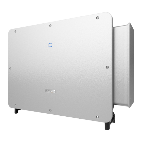
2 Product Description User Manual Product Introduction Model Description The model description is as follows(take SG350HX-US as an example). Appearance The following figure shows the appearance of the inverter. figure 2-2 Appearance The image shown here is for reference only. The actual product received may differ. Description Name To indicate the current working state of the inverter. -
Page 19: Symbols On Product
The following figure shows the dimensions of the inverter. figure 2-3 Product Dimensions(in mm) Weight Model Weight SG350HX-US ≤ 122 kg SG200HX-US Symbols on Product Symbol Explanation Do not dispose of the inverter together with household waste. Read the user manual before maintenance! CSA mark of conformity. -
Page 20: Led Indicator
2 Product Description User Manual Symbol Explanation Disconnect the inverter from all the external power sources be- fore maintenance! Burn danger due to the hot surface that may exceed 60℃. Danger to life due to high voltages! Do not touch live parts for 5 minutes after disconnection from the power sources. -
Page 21: Dc Switch
User Manual 2 Product Description LED Color State Definition A fault occurs and the device cannot connect to the grid. The Bluetooth connection is established, data commu- Blink nication in process, and a system fault occurs. Both the AC and DC sides are powered down. Gray Voltage may still be present in AC side circuits after the indicator is off. -
Page 22: Function Description
2 Product Description User Manual figure 2-4 Circuit Diagram • DC Switches can safely disconnect the PV input when necessary to ensure the safe op- eration of the inverter and the safety of personnel. • The DC SPD provides a discharge circuit for the DC side overvoltage to prevent it from damaging the internal circuits of the inverter. - Page 23 User Manual 2 Product Description Parameter Configuration The inverter provides various settable parameters. Users can set parameters via the App to meet the requirements and optimize the performance. Communication Interface The inverter is designed with standard RS485 communication interfaces. The standard RS485 communication interfaces are used to establish communication con- nection with monitoring devices and upload monitoring data by using communication cables.
-
Page 24: Unpacking And Storage
• Check the inner contents for damage after unpacking. Contact SUNGROW or the transport company in case of any damage or incompleteness, and provide photos to facilitate services. Do not dispose of the original packing case. It is recommended to store the device in the original packing case when the product is decommissioned. - Page 25 User Manual 3 Unpacking and Storage step 2 Remove the packing box upwards. step 3 Remove the surrounding paper angle beads. step 4 Remove the upper cushion.
-
Page 26: Inverter Storage
3 Unpacking and Storage User Manual - - End Inverter Storage Proper storage is required if the inverter is not installed immediately. • Store the inverter in the original packing case with the desiccant inside. • The storage temperature must be always between -40℃ and +70℃, and the storage rel- ative humidity must be always between 0 and 95 %, non-condensing. -
Page 27: Mechanical Mounting
Mechanical Mounting Respect all local standards and requirements during mechanical installation. Safety During Mounting Make sure there is no electrical connection before installation. Before drilling, avoid the water and electricity wiring in the wall. Poor installation environment will affect system performance! •... -
Page 28: Location Requirements
The ambient temperature and relative humidity must meet the following requirements. • Please consult SUNGROW before installing inverters outdoors in areas prone to salt damage, which mainly are coastal areas within 500 meters of the coast. The deposition of salt fog varies largely with nearby seawater characteristics, sea wind, precipitation, rel- ative humidity, terrain, and forest coverage. -
Page 29: Carrier Requirements
User Manual 4 Mechanical Mounting • Install the inverter in a sheltered area to avoid direct sunlight and bad weather (e.g. snow, rain, lightning, etc.). The inverter will derate in high temperature environments for protec- tion. If the inverter is installed in direct sunlight, it may cause power reduction as the tem- perature rises. - Page 30 4 Mechanical Mounting User Manual Inverters in floating plants cannot be installed at a back tilt.
-
Page 31: Clearance Requirements
User Manual 4 Mechanical Mounting In case the installation site is a level surface, mount the inverter to the bracket to meet the mounting angle requirements, as shown in the figure below. Take the following items into account when designing the bracket scheme: •... - Page 32 (not recommended). The baffle plate should be placed horizontally between two inverters and should not block the air inlet and outlet of inverters. *Please contact SUNGROW for more information about wall-mounted installation.
-
Page 33: Installation Tools
User Manual 4 Mechanical Mounting Installation Tools Installation tools include but are not limited to the following recommended ones. If necessary, use other auxiliary tools on site. table 4-1 Tool specification Goggles Earplugs Dust mask Safety gloves Safety shoes Utility knife Slotted screwdriver Phillips screwdriver (M2, M3, M6) -
Page 34: Moving Inverter
4 Mechanical Mounting User Manual crimping tool(10 Connector wrench Multimeter Vacuum cleaner AWG or 8 AWG) (≥ 1500 Vdc) Model: PV-CZM- 22100 Manufacturer: STAUBLI Scissors Hexagon socket Electric drill wrench (φ12) (T30) Moving Inverter Move the inverters by carrying them manually or using a hoisting tool based on site conditions. -
Page 35: Manual Transport
User Manual 4 Mechanical Mounting 4.4.1 Manual Transport Install the four screw-in handles that are provided to the inverter lugs and the base. Lift and move the inverter to the destination by holding the bottom handles and the four installed handles. - Page 36 4 Mechanical Mounting User Manual When handling the inverter, do not remove the cushion to avoid damage to the housing or bottom terminals. step 2 Lead the sling through the two lifting rings and fasten the tie-down strap. step 3 Hoist the inverter, and stop to check for safety when the inverter is 100 mm above the ground.
-
Page 37: Installing Mounting-Bracket
User Manual 4 Mechanical Mounting step 4 Remove the lifting rings and reassemble the sealing screws released in Step 1. Keep the inverter balanced throughout the hoisting process and avoid collisions with walls or other objects. Stop hoisting in the event of severe weather, such as heavy rain, thick fog, or strong wind. -
Page 38: Bracket-Mounted Installation
4 Mechanical Mounting User Manual Reserve enough space when installing the mounting-bracket to meet the installation space requirements of the inverter. 4.5.1 Bracket-Mounted Installation Tools Item Specification Phillips screwdriver Marker Level Electric drill Drill bit: φ12 Wrench Opening: 16 mm Spare parts Quantity Specification... - Page 39 User Manual 4 Mechanical Mounting step 2 Place the assembled mounting-bracket onto the PV bracket. Adjust the angle with a level and mark positions for drilling holes. Drill the holes by using an electric drill. step 3 Secure the mounting-bracket with bolts. (A) Mounting-bracket (B) Full threaded bolt (C) Metal bracket...
-
Page 40: Pole-Mounting
4 Mechanical Mounting User Manual 4.5.2 Pole-Mounting Tools Item Specification Phillips screwdriver — Marker — Level Electric drill * Drill bit: φ12 Wrench Opening: 16 mm * Check whether other tools are needed according to the specification of clamp bolts. Spare parts Quantity Specification... - Page 41 User Manual 4 Mechanical Mounting step 4 Use bolts and clamps to fix the U-beam to the pole. step 5 Use bolts to secure the mounting-bracket to the U-beam.
-
Page 42: Installing The Inverter
4 Mechanical Mounting User Manual - - End Installing the Inverter Tools Item Specification Phillips screwdriver Spare parts Item Quantity Specification Source Grub screw M6×65 Delivery scope step 1 If the installation position is high, hoist the inverter to the position (refer to "4.4.2 Hoisting Transport"). - Page 43 User Manual 4 Mechanical Mounting It is necessary to secure the left and right sides of the inverter to the mounting- bracket with screws, otherwise the inverter may become unstable. - - End...
-
Page 44: Electrical Connection
Electrical Connection Safety Instructions The PV string will generate lethal high voltage when exposed to sunlight. • Operators must wear proper personal protective equipment during electrical connections. • Must ensure that cables are voltage-free with a measuring instrument before touching DC cables. •... - Page 45 User Manual 5 Electrical Connection • Do not damage the ground conductor. Do not operate the product in the ab- sence of a properly installed ground conductor. Otherwise, it may cause per- sonal injury or product damage. • Please use measuring devices with an appropriate range. Overvoltage can dam- age the measuring device and cause personal injury.
-
Page 46: Terminal Description
5 Electrical Connection User Manual • After being crimped, the OT terminal must wrap the wires completely, and the wires must contact the OT terminal closely. • When using a heat gun, protect the device from being scorched. • Before connecting a power cable (such as the AC cable, the DC cable, etc.), confirm that the label and identifier on the power cable are correct. -
Page 47: Electrical Connection Overview
User Manual 5 Electrical Connection Item Terminal Mark Note 24/32, PV connector (SG350HX-US) PV terminals + / - 24, PV connector (SG200HX-US) AC wiring — Used for AC output cable connection. terminal Communica- For RS485 communication wiring. COM1 tion terminal... - Page 48 5 Electrical Connection User Manual table 5-1 Cable Requirements Specification Type Cable Conductor Cross-sec- tional Area 10 AWG PV cable complying with 1,500V DC cable standard 8 AWG (optional) External Outdoor single-core copper wire ≥ S/2 grounding cable cable Outdoor four-core copper / alumi- num wire cable Outdoor three-core copper / alu- minum wire cable...
-
Page 49: Crimp Ot/Dt Terminal
User Manual 5 Electrical Connection Crimp OT/DT terminal Crimp OT/DT terminal 1. Heat shrink tubing 2. OT/DT terminal 3. Hydraulic pliers 4. Heat gun Aluminum Cable Requirements If an Aluminum cable is selected, use a copper to Aluminum adapter terminal to avoid direct contact between the copper bar and the Aluminum cable. -
Page 50: External Protective Grounding Connection
5 Electrical Connection User Manual figure 5-2 Aluminum Cable Connection 1. Copper to Aluminum adapter terminal 2. Flange nut 3. Aluminum cable Ensure that the selected terminal can directly contact with the copper bar. If there are any problems, contact the terminal manufacturer. Ensure that the copper bar is not in direct contact with the aluminum wire. -
Page 51: External Protective Grounding Requirements
AC side grounding terminal are reliably grounded. The grounding connection can be made by other means if they are in accordance with the local standards and regulations, and SUNGROW shall not be held liable for the possible consequences. -
Page 52: Ac Cable Connection
When multiple inverters are connected to the grid in parallel, ensure that the maximum num- ber of inverters connected in parallel to a single winding of the box-type substation is 15. Otherwise, please contact SUNGROW for technical scheme. MV Transformer The MV transformer used together with the inverter should meet the following requirements: •... - Page 53 The apparent power of the inverter should never exceed the power of the transformer. The maximum AC current of all inverters connected in parallel must be taken into ac- count. If more than 15 inverters are connected to the grid, contact SUNGROW. •...
-
Page 54: Requirements For Ot/Dt Terminal
5 Electrical Connection User Manual required. It is recommended to adopt graduated protection to ensure that in an event of a single short-circuit fault on the LV side of the box, the corresponding branch MCCB trips normally while the general ACB does not trip. •... -
Page 55: Connection Procedure
User Manual 5 Electrical Connection OT/DT Terminal of PE Wire • Specification: M12 5.6.3 Connection Procedure This section introduces the connection steps with four-core cable as an example, and the wiring method for three-core cable is the same. step 1 Disconnect the AC-side circuit breaker and prevent it from inadvertent reconnection. step 2 Loosen the two screws on the front cover of the junction box with the hexagon socket wrench provided. - Page 56 5 Electrical Connection User Manual step 4 Lead the cable with the protective layer removed through the conduit. step 5 Open the protection cover.
- Page 57 User Manual 5 Electrical Connection step 6 Fix cables with crimped OT/DT terminals to corresponding terminals.
- Page 58 5 Electrical Connection User Manual Ensure that the depth L of the socket used is not less than 28 mm. step 7 Close the protection cover. step 8 Remove the limit rod and place it in place. Close the junction box and tighten the two screws on its front cover with the hexagon socket wrench provided.
-
Page 59: Dc Cable Connection
User Manual 5 Electrical Connection DC Cable Connection The PV string will generate lethal high voltage when exposed to sunlight. • Respect all safety instructions listed in relevant documents about PV strings. • Make sure the PV array is well insulated to ground before connecting it to the inverter. -
Page 60: Pv Input Configuration
5 Electrical Connection User Manual The following requirements about PV string connection must be met. Otherwise, it may cause irreversible damage to the inverter, which is not covered by the warranty. • Mixed use of PV modules of different brands or models in one MPPT circuit, or PV modules of different orientation or inclination in a string may not damage in- verter, but will cause system bad performance! 5.7.1 PV Input Configuration... -
Page 61: Assembling Pv Connectors
User Manual 5 Electrical Connection Terminal Configuration Description Please refer to the following requirements for DC terminal connection: • If the number of actual PV strings is less than the number of PV strings that can be con- nected to the inverter, ensure that each MPPT is connected with at least one string. •... -
Page 62: Installing Pv Connector
5 Electrical Connection User Manual step 2 Assemble the cable ends with the crimping pliers. 1: Positive crimp contact 2:Negative crimp contact step 3 Lead the cable through the cable gland, and insert the crimp contact into the insulator until it snaps into place. - Page 63 User Manual 5 Electrical Connection step 2 Check the cable connection of the PV string for polarity correctness and ensure that the open circuit voltage in any case does not exceed the inverter input limit of 1,500V. The multimeter must have a DC voltage range of at least 1,500 V. If the voltage is a negative value, the DC input polarity is incorrect.
-
Page 64: Rs485 Connection(Com1)
5 Electrical Connection User Manual - - End RS485 Connection(COM1) 5.8.1 Interface Description The inverter communication terminal COM1 is located at the bottom of the inverter, as shown in the figure below. table 5-2 COM1 Terminal Definition Description Port Definition RS485A IN, RS485 differential sig- nal+ RS485A IN, RS485 differential sig-... -
Page 65: Connection Procedure
User Manual 5 Electrical Connection (A) Inverter (B) Data Logger (C) PC Multi-inverter Communication System In case of multiple inverters, all the inverters can be connected via RS485 cables in the daisy chain manner. The communication cable of the tracking system can be connected to the port RS485_2 of any inverter in the daisy chain. - Page 66 5 Electrical Connection User Manual step 3 Select a seal according to the cable outer diameter. Lead the cable through the swivel nut, seal and the cable gland. step 4 Strip the protective layer and the insulation layer of the cable to proper length. step 5 Secure the wires to corresponding terminals.
- Page 67 User Manual 5 Electrical Connection step 6 Pull cables outwards to confirm whether they are fastened firmly, then tighten the swivel nut with appropriate torque. step 7 Remove the waterproof lid from the communication terminal COM1. step 8 Insert the connector into the communication terminal.
-
Page 68: Plc Communication Connection
PLC Communication Connection With a PLC communication module built inside, the inverter can communicate with the Data Logger provided by SUNGROW. For specific wiring method, refer to the user manual for the data logger. The maximum PLC communication distance from the box-type substation to the inverter is: •... - Page 69 If there is one wire per phase, with multi-core cable, the maximum communication dis- tance is 1000 m. • The Data Logger is an optional device that can be ordered from SUNGROW. • The Data Logger conducts data communication by directly using the AC output cable of the inverter and thus saves the trouble to lay and maintain the special communication cables.
-
Page 70: Commissioning
Commissioning Inspection Before Commissioning Check the following items before starting the inverter: • All equipment has been reliably installed. • DC switch(es) and AC circuit breaker are in the "OFF" position. • The ground cable is properly and reliably connected. •... - Page 71 User Manual 6 Commissioning step 2 Close the AC circuit breaker between the inverter and the grid. step 3 Install the iSolarCloud App, see "7.2 Installing App" for details. step 4 Set initial protection parameters via the iSolarCloud App when the inverter is connected to the grid for the first time (see Step 4 in "7.3.2 Login Procedure"...
-
Page 72: Isolarcloud App
iSolarCloud App Brief Introduction The iSolarCloud App can establish communication connection to the inverter via the Blue- tooth, thereby achieving near-end maintenance on the inverter. Users can use the App to view basic information, alarms, and events, set parameters, or download logs, etc. Screenshots in this manual are based on the Android system V2.1.6 , and the ac- tual interfaces may differ. -
Page 73: Login
User Manual 7 iSolarCloud App Login 7.3.1 Requirements The following requirements should be met: • The AC or DC side of the inverter is powered-on. • The mobile phone is within 5 meters away from the inverter and there are no obstructions in between. - Page 74 7 iSolarCloud App User Manual figure 7-1 Bluetooth Connection step 3 Enter the identity verification interface after the Bluetooth connection is established.
- Page 75 If the dis- tributor is unable to provide the required information, contact SUNGROW. step 4 If the inverter is not initialized, you will enter the quick setting interface of initializing protec- tion parameters.
-
Page 76: Function Overview
7 iSolarCloud App User Manual - - End Function Overview The App provides parameter viewing and setting functions, as shown in the following figure. figure 7-4 App Function Tree Map Home After login, the home page is as follows:... - Page 77 User Manual 7 iSolarCloud App figure 7-5 Home Page table 7-1 Home Page Description Designation Description System date and time of the inverter Date and time Present operation state of the inverter. For details, refer to Inverter state "table 7-2 Description of Inverter State".
-
Page 78: Run Information
7 iSolarCloud App User Manual table 7-2 Description of Inverter State Description State After being energized, inverter tracks the PV arrays’ maximum power point (MPP) and converts the DC power into AC power. This is the nor- mal operation mode. Stop Inverter is stopped. - Page 79 User Manual 7 iSolarCloud App table 7-4 Run Information Classifica- Description Parameter Name tion String n Voltage The input voltage of String n String n Current The input current of String n Information Total On-grid Run- ning Time Daily On-grid Run- ning Time Negative Voltage to Inverter DC side negative to ground voltage value...
-
Page 80: Records
7 iSolarCloud App User Manual Classifica- Description Parameter Name tion Phase C Current Records Tap Records on the navigation bar to enter the interface showing event records, as shown in the following figure. figure 7-6 Records Fault Alarm Record Tap Fault Alarm Record to enter the interface, as shown in the following figure. figure 7-7 Fault Alarm Record to select a time segment and view corresponding records. - Page 81 User Manual 7 iSolarCloud App figure 7-8 Detailed Fault Alarm Information Yield Record Tap Yield Record to enter the interface showing daily power generation as shown in the fol- lowing figure. figure 7-9 Power Curve The App displays power generation records in a variety of forms, including daily power gen- eration histogram,, monthly power generation histogram, annual power generation histo- gram and total power generation histogram.
-
Page 82: More
7 iSolarCloud App User Manual Description Parameter Monthly yield Shows the power output every month in a year. histogram Annual yield Shows the power output every year. histogram Tap the time bar on the top of the interface to select a time segment and view the corre- sponding power curve. -
Page 83: Operation Parameters
User Manual 7 iSolarCloud App figure 7-11 System Parameters * The image shown here is for reference only. Boot/Shutdown Tap Boot/Shutdown to send the boot/shutdown instruction to the inverter. Date Setting/Time Setting The correct system time is very important. Wrong system time will directly affect the data logging and power generation value. -
Page 84: Power Regulation Parameters
7 iSolarCloud App User Manual figure 7-13 PID Parameters table 7-6 PID Parameter Description Description Parameter Availability of Q at If this switch is turned on, PID recovery and Q at night can be en- Night during PID abled at the same time, but can not work at the same time. Recovery Enable/Disable the PID night recovery function. - Page 85 User Manual 7 iSolarCloud App figure 7-14 Active Power Regulation table 7-7 Active Power Regulation Definition/Setting Range Parameter Description The switch for enabling/dis- Active Power Soft abling the soft start function Enable/Disable Start after Fault after a fault occurs. Time that the soft start takes to Active Power Soft raise the power from 0 to 1s~1200s...
- Page 86 7 iSolarCloud App User Manual Definition/Setting Range Parameter Description Select whether to shut down Shutdown When Ac- the inverter when the limited Enable/Disable tive Power Limit to 0% power reaches 0. Switch used to ensure that the 100% Scheduling to inverter operates at the maxi- achieve active mum active power when the...
- Page 87 User Manual 7 iSolarCloud App Definition/Setting Description Range Parameter Reactive closed-loop Switch for enabling/disabling Enable/Disable control the closed-loop control during reactive power. Reactive power regula- Switch for selecting reactive Off/PF/Qt/Q(P)/Q(U) tion mode power regulation mode The inverter provides the reactive power regulation function. Enable this function under Re- active Power Regulation Mode and select the appropriate mode.
- Page 88 7 iSolarCloud App User Manual Definition/Setting Description Range Parameter Select corresponding curve according to Q(P) Curve A, B, C local regulations Output power at P1 on the Q(P) mode QP_P1 0 ~ 100% curve (in percentage) Output power at P2 on the Q(P) mode QP_P2 20% ~ 100% curve (in percentage)
- Page 89 User Manual 7 iSolarCloud App table 7-11 “Q(U)” Mode Parameter Descriptions: Definition/Setting Description Range Parameter Switch for enabling/disabling reactive Reactive Response Enable/Disable response Reactive Response Completion time of reactive response 0.1s~600.0s Time Select corresponding curve according to lo- Q(U) Curve A, B, C cal regulations Voltage hysteresis ratio on the Q(U) mode...
-
Page 90: Communication Parameters
7 iSolarCloud App User Manual figure 7-17 Q(U) Curve 7.8.4 Communication Parameters Serial Port Parameters Tap Settings→Communication Parameters→Serial Port Parameters to enter the corre- sponding interface, as shown in the following figure. figure 7-18 Serial Port Parameters table 7-12 Serial Port Parameters Range Parameter Device Address... -
Page 91: Firmware Update
User Manual 7 iSolarCloud App figure 7-19 MPLC Parameters table 7-13 MPLC Parameters Range Parameter Band Num Band1, Band2 Array ID 1–255 Winding ID 1–10 7.8.5 Firmware Update To avoid download failure due to poor on-site network signal, it is recommended to download the firmware package to the mobile device in advance. -
Page 92: Password Changing
7 iSolarCloud App User Manual step 9 Wait for the file to be uploaded. When the upgrade is finished, a message is displayed indi- cating that the upgrade is completed. Tap Complete to end the upgrade. - - End 7.8.6 Password Changing Tap Modify Password to enter the modify password interface, as shown in the following figure. -
Page 93: Troubleshooting And Maintenance
App or the LCD. Modify the overvoltage protection values with the con- sent of the local electric power operator. 3. Contact Sungrow Customer Service if the pre- ceding causes are ruled out and the fault persists. Generally, the inverter will be reconnected to the grid after the grid returns to normal. - Page 94 2. Check whether the protection parameters are appropriately set via the App or the LCD. 3. Contact Sungrow Customer Service if the pre- ceding causes are ruled out and the fault persists. Generally, the inverter will be reconnected to the grid after the grid returns to normal.
- Page 95 App or the LCD. 3. Contact Sungrow Customer Service if the pre- ceding causes are ruled out and the fault persists. 1. Check whether the corresponding string is of reverse polarity.
- Page 96 PV string and inverter DC input) is damaged. If Alarm so, replace the fuse. 4. Contact Sungrow Customer Service if the pre- ceding causes are ruled out and the alarm persists. *The code 548 to code 563 are corresponding to string 1 to string 16 respectively.
- Page 97 If so, replace the dam- aged cable and secure terminals to ensure a reli- able connection. 5. Contact Sungrow Customer Service if the pre- ceding causes are ruled out and the fault persists. 1. Check whether the AC cable is correctly connected.
- Page 98 2. Reconnect the communication cable of the cation Abnormal meter. Alarm 3. Contact Sungrow Customer Service if the pre- ceding causes are ruled out and the alarm persists. 1. Check whether the output port is connected to actual grid. Disconnect it from the grid if so.
- Page 99 Close the AC and DC switches in turn 15 248–255, 300– minutes later and restart the system. 322, 324–328, 3. Contact Sungrow Customer Service if the pre- 401–412, 600– ceding causes are ruled out and the fault persists. 603, 605, 608, 612, 616, 620, 622–624, 800,...
- Page 100 Close the AC and DC switches in turn 15 364-395 minutes later and restart the system. Overvoltage Fault 2. If the fault persists, please contact Sungrow Power Customer Service. 1. Check whether the number of PV modules of the corresponding string is less than other strings.
-
Page 101: Maintenance
DC side current drops below 0.5 A. 3. It is prohibited to power up the inverter again. Please contact Sungrow Customer Service. Contact SUNGROW if the measures listed in the “Troubleshooting Method” col- umn have been taken but the problem persists. Maintenance 8.2.1 Maintenance Notices... -
Page 102: Disconnecting Inverter
To avoid the risk of electric shock, do not perform any other maintenance opera- tions beyond this manual. If necessary, contact SUNGROW for maintenance. Oth- erwise, the losses caused is not covered by the warranty. -
Page 103: Routine Maintenance
User Manual 8 Troubleshooting and Maintenance step 2 Rotate the DC switch to the "OFF" position for disconnecting all of the PV string inputs. step 3 Wait about 5 minutes until the capacitors inside the inverter completely discharge. step 4 Ensure that the DC cable is current-free with a current clamp. - - End 8.2.3 Routine Maintenance Item... -
Page 104: Fan Maintenance
8 Troubleshooting and Maintenance User Manual 8.2.5 Fan Maintenance • Power off the inverter and disconnect it from all power supplies before main- taining fans. • After the inverter is powered off for 5 minutes, measure the voltage and current with professional instrument. - Page 105 User Manual 8 Troubleshooting and Maintenance step 4 Loosen screws on the sides of fans. step 5 Pull out the fans. Clean them with a soft brush or vacuum cleaner, and replace them when necessary.
-
Page 106: Heat Sink Cleaning
8 Troubleshooting and Maintenance User Manual If there is not enough space, pull out part of the fans and remove the screws be- tween the two fans. - - End 8.2.6 Heat Sink Cleaning • Power off the inverter and disconnect it from all power supplies before cleaning the heat sink. -
Page 107: Inverter Disposal
User Manual 8 Troubleshooting and Maintenance step 3 Use a soft brush or a vacuum cleaner to clean the heat sink. step 4 After cleaning the heat sink, install the fan and the rear cover plate in reverse steps. - - End Inverter Disposal 8.3.1 Dismantling the Inverter Risk of burn injuries and electric shock! -
Page 108: Disposal Of Inverter
8 Troubleshooting and Maintenance User Manual • Before dismantling the inverter, disconnect the inverter from both AC and DC power sources. • If there are more than two layers of inverter DC terminals, dismantle the outer DC connectors before dismantling the inner ones. •... -
Page 109: Appendix
Appendix Technical Data Parameters SG350HX-US SG200HX-US Input (DC) Max. PV input voltage 1500 V Min. PV input voltage / Start- 500 V / 550 V up input voltage Nominal PV input voltage 1000 V 1080 V MPP voltage range 500 V – 1500 V... - Page 110 9 Appendix User Manual Parameters SG350HX-US SG200HX-US Efficiency Max. efficiency / CEC 99.02 % / 98.5% 98.9 % / 98.5% efficiency Protection DC reverse connection protection AC short circuit protection Leakage current protection Grid monitoring Ground fault monitoring DC switch / AC switch...
-
Page 111: Wring Distance Of Di Dry Contact
User Manual 9 Appendix Parameters SG350HX-US SG200HX-US UL1741, UL62109-1, CSA UL1741, UL62109-1, CSA C22.2 No.107.1-16, C22.2 No.107.1-16, IEEE1547-2018, IEEE1547-2018, IEEE1547.1-2020, UL1741 Compliance IEEE1547.1- 2020, SA/SB, California Rule21, UL1741 SA/SB, California and FCC Part 15 Class A Rule21, HECO SRD V2.0 Limit Q at night function, LVRT, HVRT,active &... -
Page 112: Quality Assurance
300Ω; and when there are multiple inverters connected in the daisy chain, en- sure that the impedance is less than 300Ω/number of inverter. Quality Assurance When product faults occur during the warranty period, SUNGROW will provide free service or replace the product with a new one. Evidence During the warranty period, the customer shall provide the product purchase invoice and date. -
Page 113: Contact Information
• The customer shall give SUNGROW a reasonable period to repair the faulty device. Exclusion of Liability In the following circumstances, SUNGROW has the right to refuse to honor the quality guarantee: • The free warranty period for the whole machine/components has expired. - Page 114 Sungrow Power Supply Co., Ltd. www.sungrowpower.com...
Need help?
Do you have a question about the SG200HX-US and is the answer not in the manual?
Questions and answers