
Related Manuals for Sungrow SG20KTL


Summarization of Contents
About This Manual
Manual Purpose and Usage
Manual provides guidelines for connecting and operating the inverter.
Related Documents and Target Audience
Manual refers to external docs; targeted at technical staff and owners.
Symbols Explanation
Hazard Level Symbols
DANGER, WARNING, CAUTION indicate risk levels and potential injuries.
Informational Symbols
NOTICE for damage risk, NOTE for additional information.
Inverter Body Symbols
Operational Safety Symbols
Symbols for waiting period, hot surfaces, qualified personnel, and load disconnection.
Safety Instructions
General Safety Directives
Critical instructions for installation, commissioning, operation, and maintenance.
Personnel Qualification Requirement
Installation and electrical work must be done by trained and qualified personnel.
Pre-Installation Safety Measures
CAUTION on handling risks and NOTICE on shipping damage.
Installation Phase Safety
DANGER on pre-installation checks and CAUTION on ventilation.
Electrical Connection Safety
NOTICE on connection standards and grid permission.
Inverter Operation Dangers
DANGER of lethal voltage from PV arrays and CAUTION on hot parts.
Cable and Connection Safety
WARNING on cable integrity and safe connections.
Maintenance and Service Safety
DANGER of incorrect service, CAUTION for observers, NOTICE on malfunctions.
Servicing Risks and ESD Precautions
NOTICE on servicing risks, ESD precautions, and handling circuit boards.
Country Settings and Label Compliance
NOTICE on country settings, WARNING on labels and regulations.
Product Introduction
Intended Usage of Inverters
Inverters are 3-phase, transformer-less units for small-scale PV power systems.
Usage Restrictions and Input Requirements
NOTICE on other usage not permitted; Class II input and grid connection via distribution board.
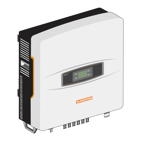
Product Appearance and Components
Identifies key components like LCD, handles, terminals, and DC switch.
Inverter Dimensions and Weight
Provides table with physical dimensions (W×H×D) and net weight for models.
LCD Display Panel Interface
Details the interface: LED indicators, buttons, and LCD screen.
LED Indicator Status Definitions
Tab. 2-1 defines RUN and FAULT LED states and their meanings.
DC Switch Operation
Explains the DC switch for safely disconnecting DC current.
Technical Principle Description
Explains the transformer-less, grid-connected principle via circuit diagram.
Key Inverter Functions
Lists functions: Conversion, Data storage, Parameters, Communication, Protection.
Derating Functionality Overview
Explains derating to protect from overload and malfunctions.
PV Overload Derating Mechanism
Power reduction when PV input exceeds limit, shown with graph.
Grid Voltage and Temperature Derating
Derating due to low grid voltage and over-temperature.
Power Limit Setting
Allows setting output power via LCD panel.
Installation Flow
Installation Flow Chart Visualization
Visual representation of the inverter installation process from start to end.
Detailed Installation Step Descriptions
Detailed steps of the installation flow with chapter references.
Unpacking and Storage
Unpacking and Inspection Procedures
Instructions for checking packing and contents for damage and completeness.
Inverter Identification and Delivery Contents
Details on nameplate, certification icons, and items included in the package.
Inverter Storage Guidelines
Proper methods for storing the inverter, covering packaging, environment, and temperature.
Installing Inverter onto Wall
Selecting Optimal Installation Location
Criteria for choosing a location for safety, efficiency, and service life.
Installation Orientation and Leveling Recommendations
Recommendations for vertical installation and avoiding tilted positions.
Environmental Considerations for Installation
Specifies temperature, humidity limits, and indoor/outdoor installation capability.
Site Placement Restrictions
Avoids direct sun, rain, snow; ensures convection space; placement of multiple units.
Installation Location Prohibitions
Prohibits closed cabinets and keeping out of reach of children.
Moving Inverter and Noise Consideration
Guides for moving the unit and avoiding living areas due to noise.
Inverter Mounting with Backplate
Explains mounting the inverter using the provided backplate.
Mounting on Concrete Wall Procedure
Step-by-step guide for attaching the backplate to a concrete wall.
Mounting on Metal Frame Procedure
Step-by-step guide for attaching the backplate to a metal frame.
Securing Inverter to Backplate
Illustrates attaching the inverter to the backplate with screws.
Electrical Connection
Terminal Descriptions and Identification
Identifies and describes all electrical terminals on the inverter.
Simplified Electrical Connection Diagram
Shows how to connect the inverter to the PV system and grid.
AC Side Electrical Requirements
Requirements for AC circuit breakers, residual current devices, and parallel connections.
AC Cable Specifications and Selection
Details AC cable types, grid impedance, and maximum lengths.
Connecting Inverter to AC Grid
Step-by-step guide for connecting to the AC grid with safety warnings.
SG10-15KTL AC Grid Connection
Specific procedure for connecting SG10-15KTL models to the AC grid.
SG20KTL AC Grid Connection
Specific procedure for connecting SG20KTL model to the AC grid.
Connecting Inverter to PV Arrays
Instructions and safety warnings for connecting to PV arrays.
PV Input Configuration Modes
Explains Independent and Parallel modes for PV inputs.
Independent Mode PV Connection Details
Details for connecting PV strings in Independent mode and input specifications.
Parallel Mode PV Connection Details
Details for connecting PV strings in Parallel mode and input specifications.
Assembling DC Cables to Connectors
Procedures for assembling DC cables to connectors, maintaining IP65.
DC Wiring Procedures and Independent Mode
General DC wiring steps, including DANGER and Independent Mode connection.
PV Connection in Independent Mode Steps
Step-by-step guide for connecting PV arrays in Independent mode.
PV Connection in Parallel Mode Steps
Step-by-step guide for connecting PV arrays in Parallel mode.
Inverter Grounding System Overview
WARNING on DC grounding and overview of grounding system.
Second Protective Earth Terminals
Description and connection of the secondary PE terminals.
Communication Connection Overview
Explains RS485 interface for data transfer to PC/logger.
Communication System Configuration
Communication systems for single/multiple inverters, cable requirements.
RS485 Communication Connection Steps
Step-by-step guide for connecting RS485 cables and devices.
Connecting External Devices and Parameters
Connecting other devices and configuring communication parameters.
Commissioning
Pre-Commissioning Inspection Checklist
Checklist of items to verify before starting inverter commissioning.
Commissioning Procedure Steps
Step-by-step guide for starting up and configuring the inverter.
Language, Time, and Country Code Settings
Setting language, time, country code for protective parameters.
Grid Code and Parameter Type Selection
Selecting grid codes (LV/MV) and protective parameter types.
Setting Confirmation and Startup Process
Final confirmation of settings and inverter startup, monitoring indicators.
Disconnecting, Dismantling, and Disposing
Safe Inverter Disconnection Procedures
Procedures for safely disconnecting the inverter from AC and DC power sources.
Inverter Dismantling and Disposal
Instructions to dismantle and dispose of the inverter according to regulations.
Troubleshooting and Maintenance
Troubleshooting Overview and LED Indicators
General troubleshooting guide and solutions for LED indicator issues.
LCD Screen Fault Code Troubleshooting
Detailed steps for fault codes displayed on the LCD screen.
Advanced Fault Code Troubleshooting
Continues fault code troubleshooting for grid, overload, and communication issues.
Routine Maintenance Procedures
Routine maintenance tasks and general instructions.
Fan Cleaning and Maintenance Instructions
Detailed procedures for fan cleaning and other maintenance, with safety precautions.
Fan Replacement and Airflow Maintenance
Instructions for fan replacement and cleaning air inlets/outlets.
Contacting Sungrow Service Support
Contact information and details needed for technical assistance.
Operation of LCD Display Panel
LCD Buttons and Navigation Guide
Explains the functions of the ESC and ENTER buttons for navigation.
Inverter Menu Structure and Navigation
Visual representation of the inverter's menu tree and navigation flow.
Main Screen Information Display
Describes the data shown on the main screen (power, energy, state).
Inverter States, Icons, and Contrast Adjustment
Details inverter states, icon meanings, and contrast adjustment.
Accessing Detailed Running Information
How to access and interpret detailed running data (DC/AC power, energy).
Viewing History and Fault Records
How to view historical running data and fault records.
Starting, Stopping, and Parameter Password
Procedures for starting/stopping and accessing parameter settings via password.
System Parameters: Language, Time, and Energy Adjustment
Setting language, time, and adjusting energy readings.
Load Default Settings and Firmware Version
Restoring default settings and viewing firmware version information.
Running Parameter Configuration Guide
Setting running parameters such as standby time, recovery time, P-W limits.
Reactive Power Regulation Modes
Activating and selecting modes for reactive power regulation (Pf, Qt, Q(P), Q(U)).
Italy Specific Reactive Power Q(P) Mode
Italy-specific Q(P) mode parameters and regulation curves.
Italy Specific Reactive Power Q(U) Mode
Italy-specific Q(U) mode parameters and regulation curves.
Protective Parameters Setting
Setting protective parameters, including country code selection.
Grid Code and Protective Parameter Type Selection
Selecting grid codes (LV/MV) and protective parameter types.
Single-stage Protective Parameters (Italy Not Applicable)
Configuring single-stage parameters for grid voltage/frequency.
Multi-stage Protective Parameters (Italy Not Applicable)
Configuring multi-stage parameters for grid voltage/frequency.
Communication Parameters Setting
Setting communication parameters like address.
PV Configuration Mode Setting
Setting PV string connection mode (Independent/Parallel).
Special Settings for Italy Overview
Overview of special LCD menus and operations for Italy.
Italy Over-frequency Derating
Configuring derating slope for Italian grid frequency.
Italy Reactive Power Regulation Q(P) Mode
Italy-specific Q(P) mode parameters and regulation curves.
Italy Reactive Power Regulation Q(U) Mode
Italy-specific Q(U) mode parameters and regulation curves.
Italy Protective Parameters Setting
Italy-specific parameter settings for grid recovery values.
Italy Stage I Protective Parameters
Configuration of Stage I protective parameters for Italy.
Italy Stage II Protective Parameters
Configuration of Stage II protective parameters for Italy.
Appendix
Technical Data: Input and Output Specifications
Table of technical specifications for input and output side data.
Technical Data: Grid, Protections, and System Ratings
Further technical data including AC current, grid parameters, protections, efficiency.
Technical Data: Communication, Mechanical, and Certifications
Data on communication, certifications, dimensions, and weight.
Terminals and Cables Specifications
Recommended conductor sizes for AC, DC, RS485, and PE terminals.
Exclusion of Liability Statement
Disclaimer regarding liability for damages from product use or misuse.
Company Information and Contact Details
Information about Sungrow and contact details for product inquiries.
Need help?
Do you have a question about the SG20KTL and is the answer not in the manual?
Questions and answers