Table of Contents
Advertisement
Quick Links
Advertisement
Table of Contents

Related Manuals for AOpen AP5C


Summary of Contents for AOpen AP5C
- Page 1 AP5C User’s Guide...
- Page 2 Copyright Copyright © 1995 by this company. All rights reserved. No part of this publication may be reproduced, transmitted, transcribed, stored in a retrieval system, or translated into any language or computer language, in any form or by any means, electronic, mechanical, magnetic, optical, manual or otherwise, without the prior written permission of this company.
- Page 3 Disclaimer This company makes no representations or warranties, either expressed or implied, with respect to the contents hereof and specifically disclaims any warranties, merchantability or fitness for any particular purpose. Any software described in this manual is sold or licensed "as is". Should the programs prove defective following their purchase, the buyer (and not this company, its distributor, or its dealer) assumes the entire cost of all necessary servicing, repair, and any incidental or consequential damages resulting from any defect in...
- Page 4 FCC Statement FCC Class B Radio Frequency Interference Statement Note: This equipment has been tested and found to comply with the limits for a Class B digital device, pursuant to Part 15 of FCC Rules. These limits are designed to provide reasonable protection against harmful interference in a residential installation.
- Page 5 About this Manual Purpose and Scope This manual tells how to install and configure the system board. Organization This manual consists of three chapters and one appendix. Chapter 1, Features, covers the specifications, layout and components of the system board. Chapter 2, Hardware Setup, tells how to set the jumpers, upgrade the CPU and the system memory, install the system board and add expansion cards.
- Page 6 About this Manual Conventions The following conventions are used in this manual: Text entered by user, Represent text input by the user, default default settings settings and recommended selections Denotes actual messages that appear message displayed on screen Represent the actual keys that you , etc have to press on the keyboard.
-
Page 7: Table Of Contents
Table of Contents Features Specifications ............. 1-2 Board Layout............1-3 System Board Parts ........... 1-4 Microprocessor .......... 1-4 ASICs ............1-4 AMI BIOS ..........1-4 Expansion Slots......... 1-5 DRAM Sockets .......... 1-5 Two-Channel PCI Mode 4 Enhanced IDE 1-5 Super I/O Controller........1-6 Keyboard Connector........ - Page 8 Table of Contents Selecting the Flash ROM Type....2-9 Clearing the CMOS ......... 2-10 Enabling the PS/2 Mouse (Optional) ..2-10 Enabling the Onboard Super I/O Controller......... 2-11 Selecting the ECP DMA Channel .... 2-11 Memory Configuration........2-12 Installing a SIMM ........2-14 Removing a SIMM ........
- Page 9 Table of Contents AMI BIOS AMI BIOS Setup Main Menu ......3-1 Standard CMOS Setup ........3-2 Date/Time..........3-2 Floppy Drives A and B....... 3-3 Hard Disk Drives........3-4 Advanced CMOS Setup ........3-5 Typematic Rate (Chars./Sec.) ....3-6 System Keyboard ........3-7 Primary Display .........
- Page 10 Table of Contents Adapter ROM Control ......3-10 IDE Control ..........3-11 Secondary Drives Present....... 3-13 Chipset Setup Mode ........ 3-13 Chipset Features Setup ........3-14 SRAM Type*..........3-17 DRAM Control ......... 3-17 ISA Control ..........3-19 PCI Control ..........3-20 IRQ Allocated ..........
- Page 11 Table of Contents Serial Port 2..........3-26 Parallel Port ..........3-26 IRQ Active ..........3-26 Parallel Port Mode ........3-26 Utility Setup ............3-27 IDE Setup ..........3-27 Color Set ..........3-28 Default Setup ........... 3-28 Original ............ 3-28 Optimal ............ 3-29 Fail-safe...........
- Page 12 Chapter Features The AP5C is a Pentium ™ -based system board that utilizes the PCI/ISA architecture. It has three PCI slots, three ISA-AT slots and one PCI-/ISA-shared slot. The board integrates the Intel Triton 82437FX, 82438FX and 82371FB application-specific integrated circuit (ASIC) chipsets that enable the System Management Mode (SMM) function of the Pentium chip.
-
Page 13: Features
Features Specifications Microprocessor Pentium™ (3.3V) Processor 75/90/100/120/133/150/166 MHz Memory 128 MB SIMM Sockets Six 72-pin, 32-bit Intel Triton 82437FX ASICs Intel Triton 82438FX Intel Triton 82371FB SMC FDC37C665GT I/O Chip Bus Architecture PCI, ISA Expansion Slots Three PCI slots Three ISA-AT slots One PCI-/ISA-shared slot Ports One parallel port (SPP/ECP/EPP) -
Page 14: Board Layout
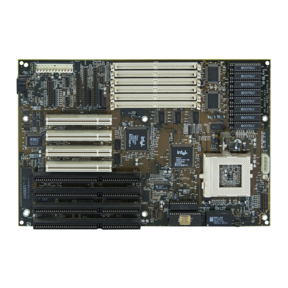
Features Board Layout 1. Keyboard controller 15. Second-level cache 2. SMC37C665GT I/O chip 16. 4-pin fan connector 3. PS/2 mouse connector 17. 2-pin fan connector 4. Keyboard connector 18. HDD LED connector 5. Power connector 19. Multifunction connector 6. Parallel connector 20. -
Page 15: System Board Parts
Features System Board Parts Microprocessor The AP5C system board uses an Intel Pentium (3.3V) processor running at speeds of 75, 90, 100, 120, 133, 150 or 166 MHz. Chapter 2 gives details on how to upgrade the Pentium processor. ASICs The ASICs onboard are the 82437FX, 82438FX and 82371FB. -
Page 16: Expansion Slots
Features Expansion Slots The board expansion slots consist of three PCI slots, three ISA-AT slots and one PCI-/ISA-shared slot. These expansion slots are the parallel bars on the system board. There are rows of golden pins inside each slot that serve as a clutch to secure the contacts of expansion boards. -
Page 17: Super I/O Controller
The system board supports 256-KB and 512-KB second-level, write- back cache. Power Management The AP5C features a system power-management mode that conforms to the power-saving standards of the U.S. Environmental Protection Agency (EPA) Energy Star program. See Chapter 3 for more information on the power-management mode. -
Page 18: Hardware Setup
Chapter Hardware Setup This chapter tells how to set jumpers, upgrade system memory, add expansion boards, and install the system board. Install the CPU, memory, and set the jumpers before you install the system board inside a system housing. You may add the other components after installing the board. -
Page 19: Installing A Microprocessor
Hardware Setup Installing a Microprocessor The motherboard has a zero-insertion force microprocessor socket that allows you to install a Pentium CPU without using any tools. Follow these steps to install a Pentium CPU in a ZIF-type upgrade socket: Make sure that the system power is OFF before installing any component. - Page 20 Hardware Setup Pull up the socket lever. Insert the CPU with the attached heatsink and fan. Make sure that pin 1 of the CPU aligns with the hole 1 of the socket. The notched corner on the CPU indicates pin 1. Pull down the socket lever to lock the CPU into the socket.
-
Page 21: Upgrading The Microprocessor
Hardware Setup Upgrading the Microprocessor Follow these steps to upgrade the Pentium CPU from 75 MHz to 90,100, 120, 133, 150 or 166 MHz: Turn off the system power. Pull up the socket lever. Remove the installed CPU. Install the upgrade CPU. Refer to the section Installing a Microprocessor for instructions on how to install a Pentium CPU. - Page 22 Hardware Setup Optional jumpers: JP6 - for PS/2 mouse function JP14, JP16 - for 3.3V or 3.3V/5V Mix Mode SRAM Set a jumper switch as follows: • To close a jumper switch, insert the plastic jumper cap over two pins of a jumper. •...
-
Page 23: Selecting The Cpu Type
Hardware Setup Selecting the CPU Type The jumpers JP9, JP10 and JP11 let you select the CPU type. The available settings are as follows: CPU TYPE JP10 JP11 P54C-75 P54C-90 P54C-100 P54C/CS/CQS-120 P54C/CS/CQS-133 P54CS/CQS-150 P54CS/CQS-166 User’s Guide... -
Page 24: Selecting The Sram Type (Optional)
Hardware Setup Selecting the SRAM Type (Optional) The system board supports both 3.3V and 3.3V/5V Mix Mode SRAMs. Set the onboard switches marked as JP14 and JP16 according to the SRAM type. See the figure below. JP14 JP16 3.3V SRAM 3.3V/5V Mix Mode SRAM Setting the Cache Size... - Page 25 Hardware Setup Follow these steps to install SRAMs: Locate the cache sockets on the system board. See the section Board Layout. Insert the SRAM chip into the socket. Align the straight edge of the chip with the straight edge of the socket. Also, make sure that the cut edge of the chip corresponds to the cut edge of the cache socket.
-
Page 26: Selecting The Flash Rom Type
Hardware Setup You must reset the 3-pin jumper JP12 when you upgrade your cache. See the figure below for the correct settings. CACHE SIZE JP12 256 KB 512 KB Selecting the Flash ROM Type Set the 3-pin jumper JP13 according to the Flash ROM type. If you use 5V Flash ROM, then you must close pins 1-2 of JP13. -
Page 27: Clearing The Cmos
Hardware Setup Clearing the CMOS The 3-pin jumper JP15 is used to clear the values in the CMOS. You need to clear the CMOS if you forget your system password. To do this, shut off the system power and short pins 2-3 of JP15 for a few seconds. -
Page 28: Enabling The Onboard Super I/O Controller
Hardware Setup Enabling the Onboard Super I/O Controller The onboard super I/O controller is SMC37C665GT. If you want to enable or disable the onboard I/O controller then you must reset the 3-pin jumper marked JP5 on the system board. Enabled Disabled Selecting the ECP DMA Channel The 3-pin jumpers JP3 and JP4 let you select the DMA channel for... -
Page 29: Memory Configuration
Hardware Setup Memory Configuration The system board supports a maximum memory of 128 MB. The six 72-pin SIMM sockets accommodate 4- and 16-MB single-density SIMMs, and 8- and 32-MB double-density SIMMs, with or without the Extended Data Output (EDO)function. The EDO feature expands data transfer cycle, thus improves memory performance. - Page 30 Hardware Setup The following are the possible SIMM configurations. Total Memory SIMM 0/1 SIMM 2/3 SIMM 4/5 8 MB 4 MB x 2 16 MB 4 MB x 2 4 MB x 2 16 MB 8 MB x 2 24 MB 4 MB x 2 4 MB x 2 4 MB x 2...
-
Page 31: Installing A Simm
Hardware Setup Installing a SIMM Observe precautions when installing components. Follow these steps to install a SIMM: Slip a SIMM at a 45 angle into a socket with the component side facing down. Always install SIMMs beginning with Bank 0. Be careful when inserting or removing SIMMs. -
Page 32: Removing A Simm
Hardware Setup Removing a SIMM Press the holding clips on both sides of the SIMM outward to release it. Press the SIMM downward to about a 45 angle. Gently pull the SIMM out of the socket. User’s Guide 2-15... -
Page 33: Connectors
Hardware Setup Connectors Multifunction Connector This 20-pin connector is marked CN14 on the system board. supports a number of system functions: green mode LED, break switch, keylock, and speaker. Attach the front panel connectors to the corresponding pins as in the illustration below. Speaker Power LED Keylock Speaker... - Page 34 Hardware Setup Speaker Keylock and Power LED Speaker Keylock & Power LED Reset Break Switch Green Mode LED ( Turbo Switch ) ( Turbo LED ) Other housings may have a 12-pin connector. If your housing has this type of connector, plug it into CN14 as shown in the following figure.
-
Page 35: Break Switch
Hardware Setup Break Switch The break switch is originally the turbo switch. It gives the user the option to directly enter the system suspend mode by setting the switch to the on position. To set, simply press the switch. Make sure that the break switch is at the off position before you set it to the on position. -
Page 36: Power Connector
Hardware Setup Power Connector A standard power supply has two cables with six wires each. Attach these cables to the power connector on the board in such a way that all the black wires are in the center. The power connector is marked CN4 on the system board. -
Page 37: Fan Connectors
Hardware Setup Fan Connectors The board has one 4-pin and one 2-pin fan connector. The 4-pin fan connector is marked CN11 on the system board and the 2-pin is marked CN12. Figure below shows the pin configuration of each connector. +12V 4-PIN FAN CONNECTOR (CN11) 4-PIN FAN CONNECTOR (J2) -
Page 38: Installation
Hardware Setup Installation The full baby-AT size of the AP5C system board easily fits most housings. It has mounting holes that conform to the standard system housing. Some housings may differ slightly in design, requiring additional steps to install the board. Read the documentation that comes with the housing. -
Page 39: Installing Expansion Boards
Hardware Setup Installing Expansion Boards Install any expansion boards after you have installed the system board into the housing. Follow these steps to install an expansion board. Remove the bracket opposite the slot that you want to use. Save the cover for future use. Save the screw to secure the expansion board. -
Page 40: Ami Bios
Chapter AMI BIOS AMI BIOS Setup Main Menu The AMI BIOS Setup Main Menu appears below. Press to enter the system menu. The AMI BIOS is in Windows form. You can use either the keyboard or a mouse to move between the items. To select among the Setup groups, use to highlight the selected group or simply click on the icon of the selected Setup menu. -
Page 41: Standard Cmos Setup
AMI BIOS You can press to enter the BIOS Setup screen. This also enables you to do the following: • Resolve an address conflict due to an IRQ address assigned to multiple slots. For more information on IRQ assignment, see the section Chipset Features Setup. -
Page 42: Date/Time
AMI BIOS Date/Time To set the date and time, highlight and press Date/Time double-click on the Date/Time icon. The following screen appears: Use the arrow keys to move among the items. Press the keys or click the + and - icons to set the current date and time. Close the window by pressing or double-clicking the Control menu box in the upper-left corner of the window. -
Page 43: Hard Disk Drives
AMI BIOS After selecting the proper setting, press or double-click the Control menu box to close the window. Select and follow the same procedure to configure the Floppy B second floppy drive, if present. Hard Disk Drives Select Master Hard Disk to configure the first hard disk. -
Page 44: Advanced Cmos Setup
AMI BIOS Advanced CMOS Setup The window below appears if you select the Advanced option. The screen above does not show all the parameters of the Advanced Configuration menu. Use to highlight the desired parameter. Press to view the rest of the parameters. The following screens appear: User’s Guide... -
Page 45: Typematic Rate (Chars./Sec.)
AMI BIOS Typematic Rate (Chars./Sec.) This parameter determines the typematic rate. The typematic rate settings are 15, 20, 30 and Disabled. The default setting is Select Disabled to disregard the rate setting. User’s Guide... -
Page 46: System Keyboard
AMI BIOS System Keyboard Set this parameter to if there is a keyboard connected to Present the system. However, some servers may not have keyboards. Select Absent if there is no keyboard present. Primary Display This function detects the type of VGA in use. The settings are VGA/EGA, CGA 40 x 25, CGA 80 x 25, Mono, and Absent. -
Page 47: Hit "Del" Message Display
AMI BIOS Hit “Del” Message Display This option lets you enable or disable the Hit <Del> if you want Setup message from appearing when the system boots. The default setting Enabled Extended BIOS RAM Area This function allows you to relocate the BIOS from ROM to RAM. Relocating to RAM enhances system performance as information access is faster than ROM. -
Page 48: Floppy Drive Swapping
AMI BIOS Floppy Drive Swapping This parameter allows you to swap floppy drives. For example, if you have two floppy drives (A and B), you can assign the first drive as drive B and the second drive as drive A or vice-versa. Disable the parameter to bypass the function. -
Page 49: System Bios Shadow Cacheable
AMI BIOS System BIOS Shadow Cacheable The default setting for this parameter is . This enhances Enabled the system performance. Disabling the parameter prevents the system BIOS from being cached. Adapter ROM Control C000, 32 K This address is for shadowing video ROMs. Select Shadow assign the address for shadowing expansion video card with ROM. -
Page 50: Ide Control
AMI BIOS IDE Control IDE Auto-detect There are cases wherein the HDD parameters that you entered and those detected by the auto-detection function are mismatched. This causes the system not to boot. If this happens, we recommend that you set this parameter to Disabled to bypass the auto-detection function. - Page 51 AMI BIOS 32-bit Mode Enabling this function improves the hard disk performance by increasing the data transfer rate from 16-bit to 32-bit. Primary 1st LBA Mode This enhanced IDE feature allows you to use a hard disk with a capacity higher than 528 MB. This is made possible through the Logical Block Address (LBA) mode translation.
-
Page 52: Secondary Drives Present
AMI BIOS Secondary 2nd LBA Mode This enhanced IDE feature allows you to use a hard disk with a capacity higher than 528 MB. This is made possible through the Logical Block Address (LBA) mode translation. This parameter affects the secondary IDE hard disk drive connected to the IDE 2 connector. -
Page 53: Chipset Features Setup
AMI BIOS Chipset Features Setup The Chipset Features Setup controls the board's chipset settings. The controls for this menu are the same as for the previous screen. The Chipset Setup DRAM control parameters differ depending on the Chipset Setup Mode setting in the Advanced CMOS Setup. This screen appears if you select the Chipset option from the Setup menu and if the Chipset Setup Mode parameter setting is End-user. - Page 54 AMI BIOS Both screens do not show all the parameters of the Chipset Setup menu. Use to highlight the desired parameter. Press view the rest of the parameters. The following screens appear regardless of the end-user type or the Chipset Setup Mode parameter setting: User’s Guide 3-15...
- Page 55 AMI BIOS 3-16 User’s Guide...
-
Page 56: Sram Type
AMI BIOS SRAM Type This parameter allows the user to select the transmission mode that your SRAM supports. The selections are Asyn, Burst and Pipelined. The Asyn or asynchronous mode is also known as the start-stop-bit transmission, wherein the transmission of data is only one-way and per character. - Page 57 AMI BIOS Read Burst Timing* This parameter adjusts the read wait state between the L2 and the DRAM cache. Everytime the CPU reads a L2 cache miss, it reads four continuous addresses from the DRAM cache. The available settings are X-4-4-4, X-3-3-3 and X-2-2-2. The value of X depends on the DRAM Lead-off Timing parameter setting.
-
Page 58: Isa Control
AMI BIOS RAS Precharge* This function lets you set the RAS precharge time. The RAS Precharge time refers to the period it takes for the core logic to charge the RAS signal before issuance. Some DRAMs require shorter time to charge RAS signals. The selections for this parameter are 3T and 4T. -
Page 59: Pci Control
AMI BIOS 16-bit I/O Recovery Time This parameter allows you to set the response time of the 16-bit I/O connected to your system. The range is from 1~4 SYSCLK. The default setting is 1 SYSCLK. PCI Control VGA Palette Snooping PCI devices support the “palette snooping”... -
Page 60: Irq Allocated
AMI BIOS PCI Secondary IDE INT# Line This parameter lets you assign an INT for the IDE device connected to your secondary IDE connector. The settings are INT A, INT B, INT C, INT D, Absent and Not Used. If you do not have any PCI IDE card installed in your system and your PCI IDE Card Selection parameter setting is Absent... -
Page 61: Power Management Setup
AMI BIOS If the same IRQ address is assigned to multiple slots, an address conflict occurs. To resolve this, press during boot-up. This enables the BIOS to reassign the IRQ addresses. Power Management Setup To take advantage of the power management features, select Power from the Setup menu. -
Page 62: Advanced Power Management
AMI BIOS Advanced Power Management Set this parameter to to take advantage of the power- Enabled saving feature. Disable the parameter to bypass the feature. Full-on to Standby Timeout This function lets you set when to put the system into standby mode. In standby mode, the CPU clock slows down and the video signal is suspended. -
Page 63: Ide Drive Power Down In
AMI BIOS IDE Drive Power Down in This option allows you to set the mode when to "spin down" your IDE hard disk. The disk returns to full speed once the system resumes to normal mode. The settings are Standby, Suspend and Disabled. Video Power Down in This option allows you to set the mode when to power down your video monitor. -
Page 64: Peripheral Setup
AMI BIOS You must enable at least one IRQ activity. Otherwise, the system stays in suspend mode. Peripheral Setup This screen appears if you select or double-click on Peripherals the Peripheral Setup icon from the Setup menu. The Peripheral Setup screen allows you to set up your system peripherals. Programming Mode The settings for this option are Auto and Manual. -
Page 65: Onboard Fdc
AMI BIOS Onboard FDC Enabling this function allows you to use the onboard floppy disk controller (FDC). The default setting is Enabled Serial Port 1 This parameter allows you to set the base address of serial port 1. The available settings are 3F8H, 2F8H, 3E8H, 2E8H and Disabled. Serial Port 2 This parameter allows you to set the base address of serial port 2. -
Page 66: Utility Setup
AMI BIOS Utility Setup IDE Setup This function allows your system to automatically configure your IDE hard disk(s). This screen appears if you select IDE Setup After a few seconds, the screen below appears showing your disk(s) parameters. Select to accept the values. User’s Guide 3-27... -
Page 67: Color Set
AMI BIOS Color Set This pop-up window appears if you select from the Color Set Utility Setup menu. Color Set lets you select the color of your windows background. The selections are LCD, Army, Pastel, and Sky. Default Setup Select this option to automatically set your system configuration parameters. -
Page 68: Optimal
AMI BIOS Optimal Choose this option and the BIOS configures the system using the best-case values to optimize system performance. However, these values may not be applicable to your system. If your system does not boot after choosing this setting, reconfigure it using the Fail-safe settings. -
Page 69: Security Setup
AMI BIOS Security Setup Password The system password prevents unauthorized use of your computer. If you enabled the password feature, it is impossible to boot the computer without entering the password. To set a password, highlight Password or simply double-click the Password icon. - Page 70 AMI BIOS If you forget your password, you must clear the CMOS RAM and reconfigure the system. To disable the password, press when prompted for your password. Press again when prompted to retype the password. User’s Guide 3-31...
-
Page 71: Anti-Virus
AMI BIOS Anti-virus Set this parameter to to protect the boot sector and Enabled partition table of your hard disk from virus intrusion. Set it to Disabled to bypass the feature. A prompt appears when you select from the Security Anti-virus Setup menu: Select... -
Page 72: Exit Setup
AMI BIOS Exit Setup To exit Setup, you can either double-click on the Control menu box or simply press . A dialog box appears on the screen. If you select , the BIOS automatically Save Changes and Exit saves all CMOS values before leaving Setup. Select Do Not to exit Setup without saving the... -
Page 73: Ncr Scsi Bios And Drivers
AMI BIOS NCR SCSI BIOS and Drivers The NCR 53C810 SCSI BIOS resides on the same flash memory chip as the system BIOS. To use the onboard NCR BIOS, you need to install an NCR 53C810 SCSI controller card in your system. All SCSI devices that you install in your system require software drivers. - Page 74 Appendix Jumper Summary CPU Type CPU Type JP10 JP11 P54C-75 1-2, 3-4 1-2, 3-4 P54C-90 1-2, 3-4 P54C-100 1-2, 3-4 P54C/CS/CQS-120 3-4, 5-6 P54C/CS/CQS-133 3-4, 5-6 P54CS/CQS-150 5-6, 7-8 P54CS/CQS-166 5-6, 7-8 SRAM Type (Optional) SRAM JP14 JP16 3.3V SRAM 3.3V/5V Mix Mode SRAM Cache Size Cache Size...
- Page 75 Jumper Summary CMOS Function JP15 Default (Normal) Clear CMOS PS/2 Mouse (Optional) Function Enabled Closed Disabled Open Onboard Super I/O Controller SMC 665GT Enabled Disabled ECP DMA Channel ECP DMA Channel DMA 3 DMA 1 User’s Guide...
- Page 76 Jumper Summary Onboard Connectors Connector Function AT-keyboard connector PS/2 keyboard connector (optional) PS/2 mouse connector (optional) Power connector Parallel port connector COM 2 connector COM 1 connector FDC connector IDE 2 connector CN10 IDE 1 connector CN11 4-pin fan connector CN12 2-pin fan connector CN13...
Need help?
Do you have a question about the AP5C and is the answer not in the manual?
Questions and answers