Table of Contents
Advertisement
Advertisement
Table of Contents

Related Manuals for AOpen AP5VM


Summary of Contents for AOpen AP5VM
- Page 1 AP5VM PART NO.:49.87530.021 DOC. NO.:AO094-9704B...
- Page 3 AP5VM Mainboard User's Guide...
- Page 4 Copyright Copyright © 1997 by this company. All rights reserved. No part of this publication may be reproduced, transmitted, transcribed, stored in a retrieval system, or translated into any language or computer language, in any form or by any means, electronic, mechanical, magnetic, optical, manual or otherwise, without the prior written permission of this company.
- Page 5 Disclaimer This company makes no representations or warranties, either expressed or implied, with respect to the contents hereof and specifically disclaims any warranties, merchantability or fitness for any particular purpose. Any software described in this manual is sold or licensed "as is". Should the programs prove defective following their purchase, the buyer (and not this company, its distributor, or its dealer) assumes the entire cost of all necessary servicing, repair, and any incidental or consequential damages resulting from any defect...
- Page 6 FCC Class B Radio Frequency Declaration of Conformity This equipment has been tested and found to comply with the limits for a Class B digital device, pursuant to Part 15 of FCC Rules. These limits are designed to provide reasonable protection against harmful interference in a residential installation.
- Page 7 Appendix C, Troubleshooting Guide, includes first aid information you need if you meet trouble, the WWW address and worldwide service telephone/fax are also included. Appendix D, AOpen Best Products, includes the best sale and recommended product specifications of AOpen.
- Page 8 Conventions The following conventions are used in this manual: Text entered user, Represent text input by the user, default settings, default settings and recommended recommended selections selections Represent the actual keys that you <Enter> <Tab>,<Ctl> <Alt> have to press on the keyboard. <Ins>, <Del>, Note: Gives bits and pieces of additional...
-
Page 9: Table Of Contents
Contents Chapter 1 Overview Specifications........1-2 Chapter 2 Hardware Installation Jumper and Connector Locations ..2-2 Jumpers..........2-4 Connectors ..........2-16 Configuring the System Memory ..2-28 Chapter 3 AMI BIOS Entering the AMI BIOS Setup ....3-1 Setup Menu ..........3-3 3.2.1 Standard Setup .......3-3 3.2.2 Advanced Setup......3-7 3.2.3 Chipset Setup.......3-12... - Page 10 Utility Setup .........3-27 Default Setup ........3-28 Exiting Setup ........3-30 Onboard NCR SCSI BIOS ....3-31 AMI Flash Utility ........3-31 Appendix A Jumper Table Summary Appendix B Frequently Asked Question Appendix C Troubleshooting Appendix D AOpen Best Products viii...
- Page 11 Chapter 1 Overview The AP5VM is a high-performance Pentium ® -based system board that utilizes the PCI/ISA architecture. It integrates the Intel 82430VX PCIset, a super I/O controller, and a PCI mode 4 enhanced IDE controller with bus master support to enhance system performance. It has four single in-line memory module (SIMM) sockets and one Dual in-line memory module (DIMM) that allow system memory expansion up to a maximum of 128MB.
-
Page 12: Overview
Overview Specifications Baby AT Form Factor 220 mm x 280 mm Board Size Intel Pentium Processor P54C, PP/MT (P55C), AMD K5 and Cyrix 6x86 FPM (Fast Page Mode) or EDO (Extended Data System Memory Output) 72-pin SIMM x4, and SDRAM 168-pin x1 maximum 128MB. -
Page 13: Hardware Installation
Chapter 2 Hardware Installation This chapter gives you a step-by-step procedure on how to install your system. Follow each section accordingly. Caution: Electrostatic discharge (ESD) can damage your processor, disk drives, expansion boards, and other components. Always observe the following precautions before you install a system component. -
Page 14: Jumper And Connector Locations
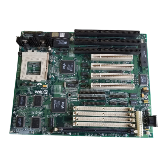
Hardware Installation Jumper and Connector Locations The following figure shows the locations of the jumpers and connectors on the system board: PS2 MS PWR 1 COM2 COM1 PRINTER FDC1 IDE2 IDE1 JP25 JP14 JP20 BIOS JP18 HDD LED JP11 IrDA JP10 PANEL JP12... -
Page 15: Jumpers
Hardware Installation Jumpers: JP1,JP2: CPU frequency ratio select JP3,JP4: CPU external (bus) clock select JP7: CPU core voltage setting (Vcore) JP8: I/O voltage setting (Vio) JP9,JP10, JP11,JP12 CPU type (Single/Dual voltage, Vcpuio) selection JP14: For clearing CMOS JP18: Enable/disable onboard super I/O controller JP20: Enable/disable onboard PS/2 mouse JP25:... - Page 16 Hardware Installation Jumper Settings Board jumpers are made of pin headers and plastic connecting caps. These are included in the mainboard design to enable you to customize your hardware. The onboard jumpers are normally set to its default and optimum setting.
- Page 17 Hardware Installation 2.2.1 Setting the CPU Voltage CPU Core Voltage (Vcore) JP7 is used to select CPU core voltage (Vcore), normally it is 3.45V (Intel P54C) set to default 3.45V for INTEL Pentium P54C. It must be 3.52V (Cyrix or AMD K5) changed if you have CPU with 2.9V (AMD K6-166/200) different core voltage, such as...
- Page 18 Hardware Installation JP8 is reserved for testing purposes I/O Voltage (Vio) only. This jumper enables you to set 3.45V (default) the voltage of the onboard chipset and 3.52V PBSRAM (Vio). For dual-voltage CPU, JP8 also functions as CPU I/O voltage (Vcpuio) controller.
- Page 19 Hardware Installation JP10 JP11 JP12 CPU Type (Vcpuio) 1-2 & Open 1-2 & Open Single Voltage CPU Vcpuio = Vcore (default) Open 1-2 & Open 1-2 & Dual Voltage CPU Vcpuio = Vio (PP/MT P55C) Set the jumpers JP9, JP10, JP11, and JP12 according to the type of CPU currently supported.
- Page 20 Hardware Installation Vcore Vcpuio JP10 JP11 JP12 Type Intel 3.45V 3.45V Vcore 1-2, Open 1-2, Open P54C Intel 2.8V 3.45V Open 1-2, Open 1-2, (P55C) AMD K5 3.52V 3.45V Vcore 1-2, Open 1-2, Open (Single voltage) Cyrix 3.52V 3.45V Vcore 1-2, Open 1-2,...
- Page 21 Hardware Installation 2.2.2 Selecting the CPU Frequency CPU Frequency The Intel Pentium, Cyrix 6x86 and AMD K5/K6 CPUs have different Ratio internal (Core) and external (Bus) 1.5x (3.5x) frequency. The ratio of Core/Bus frequency that the CPU uses to 2.5x (1.75x) multiply external clock...
- Page 22 Hardware Installation JP3 & JP4 JP3 & JP4 JP3 & JP4 1 2 3 1 2 3 1 2 3 50MHz 60MHz 66MHz Caution: The below table lists the possible settings only for the current CPUs on the market. The settings may vary in case there is a new CPU product introduced in the market.
- Page 23 Hardware Installation Cyrix 6x86 CPU Core Ratio External Bus JP1 & JP2 JP3 & JP4 Frequency Clock P120+ 100MHz = 50MHz 2-3 & 1-2 2-3 & 1-2 P150+ 120MHz = 60MHz 2-3 & 1-2 1-2 & 2-3 P166+ 133MHz = 66MHz 2-3 &...
- Page 24 Hardware Installation 2.2.3 Disabling the Onboard Super I/O Controller The board is default by the manufacturer JP18 Onboard Super I/O enable onboard Super Enabled (default) controller. In case you wish to use an Disabled external I/O controller, you need to disable the onboard I/O before the external I/O card functions.
- Page 25 Hardware Installation 2.2.4 Disabling the PS/2 Mouse Function The PS/2 mouse function is normally JP20 PS/2 Mouse enabled and occupies IRQ12. To reassign Enabled (default) IRQ12 to another function, disable the Disabled PS/2 mouse function by setting jumper JP20 to 2-3. JP20 JP20 Enabled...
- Page 26 Hardware Installation 2.2.5 Clearing the CMOS You need to clear the CMOS if you forget JP14 Clear CMOS your system password. To clear the Normal operation CMOS, do the steps that follow the figure (default) below. Clear CMOS Before you proceed, check your onboard CMOS chip.
- Page 27 Hardware Installation Locate JP14 and short pins 2-3 for a few seconds. Check your manual for the correct jumper settings and location of the jumpers. Turn on the system power. Turn off the system power again. Reset JP14 to its normal setting by shorting pins 1-2. 2.2.6 Selecting the DIMM Type JP25 Memory Type...
-
Page 28: Connectors
Hardware Installation Connectors 2.3.1 Power Cable A standard baby AT (PS/2) power supply has two cables with six wires on each cable. Plug in these cables to the onboard power connector in such a way that all the black wires are in the center. The power connector is marked PWR1 on the mainboard. - Page 29 Hardware Installation 2.3.2 CPU Fan The fan connector is marked FAN on the system board. Plug in the fan cable to this 2-pin connector onboard. Attach the heatsink and fan to the CPU. Check its orientation, make sure the air flow go through the heatsink. +12V Air Flow Heatsink...
- Page 30 Hardware Installation 2.3.4 Serial Devices (COM1/COM2) Plug in the 10-pin flat cable to the appropriate onboard connectors. The COM1 connector is marked COM1 and the COM2 connector is marked COM2 on the mainboard. Then insert the serial device connector into the serial port on the bracket.
- Page 31 Hardware Installation 2.3.5 USB Device (optional) You need a USB bracket to Description Description enable your system to support additional USB device(s). To attach a USB bracket, simply insert the bracket cable to the onboard connector marked USB. 2-19...
- Page 32 Hardware Installation 2.3.6 Floppy Drive To support a floppy drive, connect the 34-pin floppy drive cable to the floppy drive connector marked FDC1 on the mainboard. FDC1 2.3.7 Printer This connector allows you to install a printer to your system. To install, plug in the 26-pin printer flat cable to the onboard parallel connector marked PRINTER.
- Page 33 Hardware Installation 2.3.8 IDE Hard Disk and CD ROM This mainboard supports two 40-pin IDE connectors marked as IDE1 and IDE2. The IDE1 is also known as primary channel and IDE2 as secondary channel. Each channel supports two IDE devices. In order to enable the devices to work together, the two devices on each channel must be set differently to master and slave mode.
- Page 34 Hardware Installation IDE1 (Primary Channel) Slave Master (2nd) (1st) IDE2 (Secondary Channel) Slave Master (4th) (3rd) 2-22...
- Page 35 Hardware Installation 2.3.9 Hard Disk LED The HDD LED connector is marked HDD LED Description on the board. This connector is designed to HDD LED support various types of housing. Actually, only two pins are necessary for the LED. If your housing comes with a 4-pin connector, HDD LED simply attach it to the onboard connector.
- Page 36 Hardware Installation 2.3.10 Panel Connector The multifunction (panel) connector is a 20-pin connector marked PANEL on the KEYLOCK board. Attach the power LED, keylock, GREEN LED speaker, reset switch, suspend switch, and RESET green mode connectors POWER LED SUSPEND SW corresponding pins as shown in the figure.
- Page 37 Hardware Installation Notes: If your housing comes with Turbo switch and Turbo LED connectors, you may use these connectors for Suspend switch and Green mode LED functions, respectively. Pressing the Suspend switch allows you to manually set the system to suspend mode. However, this is possible only if the Power Management function in the BIOS Setup menu is enabled.
- Page 38 Hardware Installation 2.3.11 Keyboard The onboard keyboard connector is a 5-pin AT-compatible connector marked KB1. The figure below shows how the keyboard connector as viewed from the back panel of the housing. Note: The mini DIN PS/2 keyboard connector is optional. 2-26...
- Page 39 Hardware Installation 2.3.12 IrDA Connector Serial port 2 can be configured to support wireless infrared module via this connector and application software such as Laplink. This module enables the user to transfer files to or from laptops, notebooks, PDA and printers without using cables.
-
Page 40: Configuring The System Memory
Hardware Installation Configuring the System Memory This mainboard has four 72 pin SIMM sockets Pin 1 of (Single-in-line Memory Module) and one 168 pin DIMM DIMM socket (Dual-in-line Memory Module) that allow you to install system memory from Pin 1 of minimum 8MB up to maximum 128MB. - Page 41 Hardware Installation Warning: The default memory timing setting is 60ns to obtain the optimal performance. Because of the specification limitation, 70ns SIMM is recommended to be used only for CPU external clock 60MHz. Tip: EDO DRAM is designed to improve the DRAM read performance.
- Page 42 Hardware Installation For double side memory module, there is one limitation. This mainboard supports only 4 RAS# (Row address latch) signals for DRAM control. They can only be occupied by one DRAM module, they can not be shared. simple rule is: If double side module at either Bank1 or DIMM, the other must be empty.
- Page 43 Time. It is similar as CAS Access Time of EDO DRAM and is calculated as number of clock state. The SDRAM that AOpen had tested are listed below. If your SDRAM has unstable problem, go into BIOS "Chipset Features Setup", change CAS Latency Time to 3 clocks.
- Page 44 Hardware Installation Tip: The SIMM/DIMM chip count can be calculated by following example: 1. For 32 bit non-parity SIMM using 1M by 4 bit DRAM chip, 32/4=8 chips. 2. For 36 bit parity SIMM using 1M by 4 bit DRAM chip, 36/4=9 chips.
- Page 45 Hardware Installation DIMM Bit size per Single/ Chip DIMM size Recommended Data chip side Double side count 1M by 16 1Mx64 1M by 16 1Mx64 16MB 2M by 8 2Mx64 16MB 2M by 8 2Mx64 32MB Tip: 8 bit = 1 byte, 32 bit = 4 byte. The SIMM size is represented by number of data byte (whether with or without parity), for example, the size of single side SIMM using 1M by 4 bit chip is 1Mx32 bit, that is, 1M x 4 byte...
-
Page 46: Ami Bios
Chapter 3 AMI BIOS This chapter tells how to configure the system by setting the BIOS parameters. Entering the AMI BIOS Setup To enter the AMI BIOS Setup, press . The AMI BIOS Setup Main Menu appears as shown below. The AMI BIOS is in Windows form. - Page 47 AMI BIOS Utility To select among the options, you can either use the arrow keys to move the highlight bar or simply click on the icon of the desired option. After making your selection, press or double-click on the icon to open the selected menu option.
-
Page 48: Setup Menu
AMI BIOS Utility Setup Menu The figure below shows the Setup window. Use the arrow keys to highlight an option. 3.2.1 Standard Setup Standard The following screen appears if you select from the Setup options: You can input configuration values such as date, time and disk types in this menu. - Page 49 AMI BIOS Utility To configure the hard disk connected to the slave port of the primary IDE Primary Slave connector, select The secondary IDE connector also supports two IDE devices. To configure the hard disk or the IDE device connected to the master port, select Secondary Master Secondary Slave .
- Page 50 AMI BIOS Utility Type This parameter lets you set the IDE device type that your system supports. User Auto CD-ROM Type 1-46 The options are , and Installed . Select Auto to automatically configure the installed hard disk or IDE device. Select CD-ROM if you have a CD-ROM...
- Page 51 AMI BIOS Utility 32-bit Mode Enabling this parameter improves system performance by increasing the hard disk access to 32-bit mode. However, make sure that your hard disk supports this function before you enable the parameter. Otherwise, set this parameter PIO Mode Setting this parameter to allows the system to use a faster hard disk drive.
-
Page 52: Advanced Setup
AMI BIOS Utility Select the arrow keys to move among the items. Press or click on to set the current time and date. Press or double-click on the Control menu box at the upper-left corner of the window. FLOPPY DRIVES A AND B To configure the first floppy drive, select Floppy A . - Page 53 AMI BIOS Utility The first screen does not show all the parameters of the Advanced Configuration menu. To scroll down the rest of the parameters, press Press to highlight the desired parameter.
- Page 54 AMI BIOS Utility Do not change the settings of the Advanced Setup parameters if you are not a qualified technician. Doing so may cause fatal system failure. Quick Boot During boot up, the system performs power-on self test (POST) routines. Enable the parameter if you want to skip some POST routines during the boot process.
- Page 55 AMI BIOS Utility Floppy Drive Swap This parameter allows you to swap floppy drives. For example, if you have two floppy drives (A and B), you can assign the first drive as drive B and the second drive as drive A or vice-versa. Disable the parameter to bypass the Disabled function.
- Page 56 AMI BIOS Utility Internal Cache This function lets you enable or disable the internal cache. External Cache This function lets you enable or disable the external cache. System BIOS Cacheable Enabling this parameter allows you to cache the system BIOS to further Enabled.
-
Page 57: Chipset Setup
AMI BIOS Utility 3.2.3 Chipset Features Setup The Chipset Features Setup controls the board chipset settings. The controls for this menu are the same as for the previous screens. The Chipset Features Setup screen appears as follows. To scroll down the rest of the parameters, press . - Page 58 AMI BIOS Utility DRAM Timing Setting 60 ns, 70 ns, Manual The selections for this parameter are 60 ns 70 ns If you select either , the DRAM Timing subparameters become non-configurable since BIOS automatically sets the values. Select Manual if you want to specify your own parameter settings.
- Page 59 AMI BIOS Utility REFRESH RAS# ASSERTION This function controls the number of clocks required to assert RAS# for 4 clocks 5 clocks refresh cycles. The available settings are FAST EDO PATH SELECT Enable this option to select a fast path for CPU to DRAM read cycles to minimize the lead-off time.
- Page 60 AMI BIOS Utility PCI 2.1 Compliant This parameter lets you enable or disable the PIIX3 PCI register passive release functions. When enabled , the PIIX3 controls the USB operation to make sure that the system complies with the PCI Revision 2.1 specification. Disabled Select to disregard the functions.
-
Page 61: Power Management Setup
AMI BIOS Utility 3.2.4 Power Management Setup To take advantage of the power-management feature, select Power Management from the Setup menu. The following screen appears: To scroll down the rest of the parameters, press . Use highlight the desired parameter. Power Management/APM This parameter enables or disables the advanced power-management function. - Page 62 AMI BIOS Utility Instant On Time-out (Minutes) This parameter is configurable only if the Power Management/APM parameter Instant On is set to This option lets you specify when to resume system power after being in power-saving mode for a certain period of time. Green Monitor Power-down State This function lets you set when to power down your green PC monitor.
- Page 63 AMI BIOS Utility 1 ~15 Minutes to full power. The settings range from Disabled Slow Clock Ratio When the system enters the standby mode, the CPU clock starts to slow This parameter lets you set the “s l ow down ” clock ratio. down.
-
Page 64: Pci/Pnp Setup
AMI BIOS Utility 3.2.5 PCI/PnP Setup The PCI/PNP Setup allows you to specify the setting for your PCI devices. The screen below appears on screen if you select PCI/PnP from the Setup menu. To scroll down the rest of the parameters, press . - Page 65 AMI BIOS Utility PCI IRQ Priority Auto Setting Set this parameter to to automatically set the appropriate available interrupt for each PCI slot. Select if you prefer to manually set the interrupts. 1st, 2nd, 3rd, and 4th Available IRQ These parameters are configurable only if the PCI IRQ Priority Auto Setting parameter is set to .
- Page 66 AMI BIOS Utility Reserved Memory Size for ISA This option lets you specify the memory area reserved for Legacy/ISA devices. Reserved Memory Base for ISA This option lets you specify the memory base address reserved for Legacy/ISA devices. 3-21...
-
Page 67: Peripheral Setup
AMI BIOS Utility 3.2.6 Peripheral Setup Select Peripheral from the Setup menu and the following screen appears. Onboard FDC This parameter enables or disables the floppy drive controller. Onboard Serial Port 1 This parameter allows you to select the address for the first serial port. The Auto, 3F8h, 2F8h, 3E8h, 2E8h, available settings are Disabled... - Page 68 AMI BIOS Utility • HPSIR - Select this setting only if the InfraRed (IR) function is activated (i.e., an IR module is installed in your system). This setting allows infrared serial communication at a maximum baud rate of 115K baud. •...
-
Page 69: Security Setup
AMI BIOS Utility Security Setup The Security window contains the password and anti-virus features. 3.3.1 Supervisor Password The use of password prevents unauthorized use of your computer. If you set a Supervisor password, the system prompts for this password before granting access to Setup or system boot, depending on the Password Check setting in the Advanced CMOS Setup menu. - Page 70 AMI BIOS Utility Type in a six-character password using letters, numbers, or a combination of both. When you type the characters, they appear as asterisks on the password screen boxes. Press <Enter>. Retype the password when a password confirmation box appears asking you to retype the password.
- Page 71 AMI BIOS Utility Setup. 3.3.3 Anti-virus Select Anti-Virus from the Security window to display the following option box. The virus protection options allow you to enable or disable the virus protection feature. 3-26...
-
Page 72: Utility Setup
AMI BIOS Utility Utility Setup The Utility window lets you change WinBIOS Setup colors and language setting. 3.4.1 Color Set Select Color Set from the Utility window to display the following screen. Use the arrow keys or simply click an option to select your desired background color for WinBIOS. -
Page 73: Default Setup
AMI BIOS Utility Default Setup The Default window allows you to select a group of settings for all WinBIOS Setup options. 3.5.1 Original Original When you select , a dialog box prompts you to restore the original BIOS default values. Select to keep your current settings. - Page 74 AMI BIOS Utility 3.5.3 Turbo When you select Turbo , a dialog box prompts you to load the Turbo values to further enhance system performance. Select to load the Turbo values. Select to keep your current settings. In case your system operation becomes unstable and incompatibility problems occur, unload the Turbo values and 3-29...
-
Page 75: Exiting Setup
AMI BIOS Utility Exiting Setup Carefully check your new settings when you have finished configuring the system. If correct, write them down and keep the recorded values in a safe place. If in the future, the battery loses power or the CMOS chip is damaged, you will know what values to enter when you rerun setup. -
Page 76: Ami Flash Utility
The AMI Flash Utility allows you to upgrade the system BIOS. To get the AMI flash utility and the upgrade BIOS file, contact your local distributor or visit our homepage at http://www.aopen.com.tw . The file name of AMI flash utility is AMIFLASH.EXE, run this program under DOS, follow the instruction on the screen, actually, you need only input the BIOS file name. - Page 77 Appendix A Jumper Setting Summary CPU Voltage Select CPU Core Voltage (Vcore) I/O Voltage (Vio) 3.45V (Intel P54C) 3.45V (default) 3.52V (Cyrix or AMD K5) 3.52V 2.9V (AMD K6-166/200) 2.8V (MMX P55C or Cyrix M2) 9-10 3.2V (AMD K6-233) 11-12 2.5V JP10 JP11...
-
Page 78: Appendix A Jumper Table Summary
Jumper Table Summary Vcore Vcpuio JP10 JP11 JP12 Type Intel 3.45V 3.45V Vcore 1-2, Open 1-2, Open P54C Intel 2.8V 3.45V Open 1-2, Open 1-2, (P55C) AMD K5 3.52V 3.45V Vcore 1-2, Open 1-2, Open (Single voltage) Cyrix 3.52V 3.45V Vcore 1-2, Open... - Page 79 Jumper Table Summary Intel Pentium CPU Core Ratio External Bus JP1 & JP2 JP3 & JP4 Frequency Clock PP/MT 150 150MHz = 2.5x 60MHz 2-3 & 2-3 1-2 & 2-3 (P55C) PP/MT 166 166MHz = 2.5x 66MHz 2-3 & 2-3 2-3 &...
- Page 80 Jumper Table Summary Enable/Disable Onboard Super I/O Controller JP18 Onboard Super I/O Enabled (default) Disabled Enable/Disable PS/2 Mouse Function JP20 PS/2 Mouse Enabled (default) Disabled Clearing CMOS JP14 Clear CMOS Normal operation (default) Clear CMOS DIMM Memory Type Select JP25 Memory Type Open SDRAM...
- Page 81 PCI slot and is enclosed in a white bordered box. The ppppp is the project code used by AOpen internally and -x is the version code. For example, for AP53 with 95140 project code and -3 version code, the mainboard version...
- Page 82 Frequently Asked Questions Q: Why the AOpen mainboards (MB) do not have cache module expansion slot? A: Faster CPU speed requires more difficult and complex MB timing design. Every trace and components delay must be taken into consideration. The expansion cache slot design will cause 2 or 3ns delay in PBSRAM timing, and the extended trace length to the cache module through the golden finger will further delay the timing by 1 or 2ns.
- Page 83 (such as 3D video, 3D sound, video conference). The performance can be improved if applications use these instructions. All AOpen MBs have at least dual power onboard to support MMX. It is not necessary to have special chipset for MMX CPU.
- Page 84 Frequently Asked Questions Q: When can we have real jumperless mainboard? A: PnP had achieved the goal of jumperless add-on card, but true jumperless mainboard still has some technical concerns. For example, CPU clock and voltage do not have standard interface. Currently, the so called jumperless mainboard is actually depends on the BIOS to detect or manually set the CPU clock and voltage.
- Page 85 64-bit 168-pin DIMM (Dual-in-line Memory Module) and operates at 3.3V. Note that some old DIMMs are made by FPM/EDO and only operate at 5V. Do not confuse them with SDRAM DIMM. AOpen is the first company to support dual-SDRAM DIMMs onboard (AP5V), from Q1 1996.
- Page 86 Frequently Asked Questions The following table lists the transfer rate of IDE PIO and DMA modes. The IDE bus is 16-bit, which means every t ransfer is two bytes. Mode Clock per Clock Cycle Data Transfer rate 33MHz count time PIO mode 0 30ns 600ns...
- Page 87 Both external box modem and internal modem card can be used to support Modem Wake Up, but if you use external modem, you have to keep the box modem always power-on. AOpen AX5T/AX58 and internal modem card implement special circuit (patent applied) and make sure the modem card works properly without any power.
- Page 88 Frequently Asked Questions A: The Deturbo mode was originally designed to slow down CPU speed for old applications (especially old games). It uses programming loop to wait or delay special event. This programming method is considered very bad since the delay of loop highly depends on the CPU speed and the application fails at high-speed CPU.
- Page 89 A: This is a software of Intel. The major goal is to provide an easy way for corporate network administrator to monitor the status of all the clients (workstation). You need at least DMI BIOS for LDCM. AOpen BIOS is also DMI ready but unfortunately, Intel LDCM needs Intel network and ATI VGA card to work properly.
Need help?
Do you have a question about the AP5VM and is the answer not in the manual?
Questions and answers