Table of Contents
Advertisement
Advertisement
Table of Contents

Related Manuals for AOpen AP43


Summary of Contents for AOpen AP43
- Page 1 AP43 User’s Guide...
- Page 2 Copyright Copyright 1995 by this company. All rights reserved. No part of this publication may be reproduced, transmitted, transcribed, stored in a retrieval system, or translated into any language or computer language, in any form or by any means, electronic, mechanical, magnetic, optical, manual or otherwise, without the prior written permission of this company.
- Page 3 Disclaimer This company makes no representations or warranties, either expressed or implied, with respect to the contents hereof and specifically disclaims any warranties, merchantability or fitness for any particular purpose. Any software described in this manual is sold or licensed "as is". Should the programs prove defective following their purchase, the buyer (and not this company, its distributor, or its dealer) assumes the entire cost of all necessary servicing, repair, and any incidental or consequential damages resulting from any defect in...
- Page 4 FCC Statement FCC Class B Radio Frequency Interference Statement Note: This equipment has been tested and found to comply with the limits for a Class B digital device, pursuant to Part 15 of FCC Rules. These limits are designed to provide reasonable protection against harmful interference in a residential installation.
- Page 5 About this Manual Purpose and Scope This manual tells how to install and configure the system board. Organization This manual consists of three chapters and two apendices: Chapter 1, Features, covers the specifications, layout, and components of the system board. Chapter 2, Hardware Setup, tells how to set the jumpers, upgrade the CPU and the system memory, install the system board and add expansion cards.
- Page 6 About this Manual Conventions The following conventions are used in this manual: Text entered by user, Represent text input by the user, default settings default settings and recommended selections Denotes actual messages that appear message displayed on screen Represent the actual keys that you , etc have to press on the keyboard.
-
Page 7: Table Of Contents
Table of Contents Features Specifications ............. 1-2 Board Layout ............1-3 System Board Parts ........... 1-4 Microprocessor .......... 1-4 ASICs ............1-4 AMI BIOS ..........1-4 Expansion Slots ......... 1-5 DRAM Sockets .......... 1-5 Two-channel PCI Mode 4 IDE ....1-5 Super I/O Controller ........ - Page 8 Table of Contents Changing the CPU Type ......2-7 Setting the Oscillator Frequency ..... 2-13 Setting the Flash ROM Type ....2-13 Selecting the ECP DMA Channel .... 2-14 Enabling the FDC and Super I/O Chip ..2-14 Selecting the Cache Size ......2-15 Clearing the CMOS .........
- Page 9 Table of Contents AMI BIOS AMI BIOS Setup Main Menu ......3-1 Standard CMOS Setup ........3-2 Date/Time ..........3-2 Floppy Drives A and B ....... 3-3 Hard Disk Drives ........3-4 Advanced CMOS Setup ........3-5 Typematic Rate (Chars./Sec.) ....3-7 System Keyboard ........
- Page 10 Table of Contents CPU Selection ......... 3-10 Cache ............3-10 Shadow C800, D000, D800, 32K .... 3-12 Video Shadow ......... 3-12 Main BIOS Cacheable ......3-12 Cacheable C800, D000, D800, 32 K ..3-12 Video Shadow Cacheable ....... 3-13 Secondary IDE Drives Present ....3-13 Primary 1st IDE Block Mode ....
- Page 11 Table of Contents Standby Timer ......... 3-24 Suspend Timer ........3-24 Wake-up Events ........3-25 Monitor Type ........... 3-25 Display Off After ........3-25 HDD Off After .......... 3-25 Deturbo After ........... 3-26 Break Switch ........... 3-26 Peripheral Setup ..........3-26 Programming Mode .........
- Page 12 Table of Contents Fail-safe ........... 3-31 Security Setup ..........3-32 Password ..........3-32 Anti-virus ..........3-34 Exit Setup ............3-35 NCR SCSI BIOS and Drivers ......3-36 Appendix A Jumper Summary Appendix B SiS Drivers...
- Page 13 Chapter Features The AP43 is a 486-based system board that utilizes the PCI/ISA architecture. It supports the 486SX, DX, DX2, and DX4 series microprocessors. It has four ISA-AT and three PCI slots for future expansion. The system memory is expandable to 128 MB by adding single in-line memory modules (SIMMs).
-
Page 14: Features Specifications
Features Specifications Microprocessor 5V CPUs Intel SL-enhanced Intel SX/DX/DX2 AMD DX/DX2 Cyrix DX/DX2 Intel P24D Intel P24T 3.45V CPUs Intel DX4 AMD DX2 AMD DX4/DX4-S/Am5x86 Cyrix DX2/DX4/5X86 TI DX2/DX4 128 MB Maximum Memory Four 72-pin, 32-bit SIMM Sockets SiS85C496 ASIC Chips SiS85C497 ISA, PCI Bus Architecture... -
Page 15: Board Layout
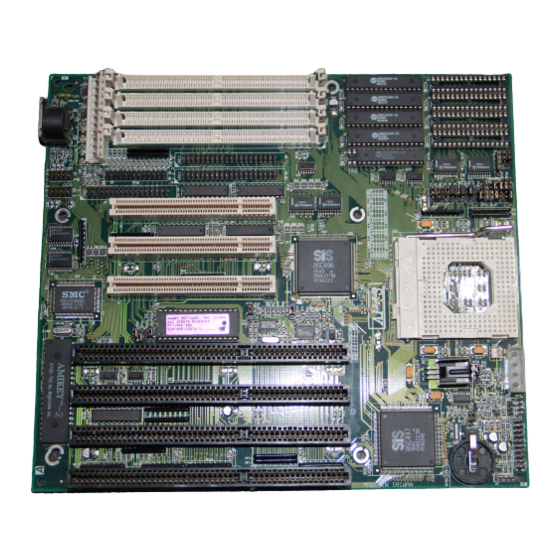
Features Board Layout Power connector 13. External battery connector Printer connector 14. Battery SIMM sockets 15. SiS 85C497 ASIC IDE1 connector 16. ISA slots IDE2 connector 17. AMI BIOS SiS 85C496 ASIC 18. PCI slots Second-level cache 19. Keyboard controller CPU socket 20. -
Page 16: System Board Parts
Features System Board Parts Microprocessor The AP43 system board supports the Intel SL-enhanced, Intel 486SX/DX/DX2/DX4, AMD 486DX/DX2/DX4/DX4-S/Am5x86, Cyrix Cx486DX/DX2/DX4/5X86 486DX2/DX4 series microprocessors. Chapter 2 tells how to upgrade the processor. ASICs The two ASICs onboard are the SiS85C496 and SiS85C497. The SiS85C496 acts as the PCI and CPU memory controller (PCM). -
Page 17: Expansion Slots
Features Expansion Slots The board expansion slots consist of four ISA-AT and three PCI slots. These expansion slots are the parallel bars on the system board. There are rows of golden pins inside each slot that serve as a clutch to secure the contacts of expansion boards. -
Page 18: Super I/O Controller
The system board supports 128-KB, 256-KB and 512-KB second- level, write-back and write-through cache. Power Management The AP43 conforms to the power-saving standards of the U.S. Environmental Protection Agency (EPA) Energy Star program. The system board features four power-saving modes that reduce power consumption. -
Page 19: Hardware Setup
Chapter Hardware Setup This chapter discusses the CPU options, tells how to set jumpers, upgrade system memory, add expansion boards, and install the system board. Install the CPU, memory, and set the jumpers before you install the board inside a housing. You may add the other components after installing the board. -
Page 20: Esd Precautions
Hardware Setup 3.45 V CPU Options 3.45V CPU Type Speed (MHz) Intel 486DX4 75/100 AMD series 486DX2 66/80 486DX4 100/120 Am5x86 Cyrix series 486DX2 V50/V66/V80 486DX4 5X86 100/120 TI series 486DX2 66/80 486DX4 ESD Precautions Electrostatic discharge (ESD) can damage your CPU, disk drives, expansion boards, and other components. -
Page 21: Installing A Microprocessor
Hardware Setup Installing a Microprocessor The motherboard has a zero-insertion force microprocessor socket that allows you to install a CPU without using any tools. Follow these steps to install a CPU in a ZIF-type upgrade socket: Make sure that the system power is OFF before installing any component. -
Page 22: Upgrading The Microprocessor
Hardware Setup Pull down the socket lever to lock the CPU into the socket. Plug the fan cable into the onboard fan connector. Set the jumpers accordingly. See the following sections for the correct jumper settings. Upgrading the Microprocessor Follow these steps to upgrade the CPU: Turn off the system power and remove the housing cover. -
Page 23: Jumper Settings
Hardware Setup Jumper Settings You have to change the jumper settings when you reconfigure the system. This section tells how to set the jumpers. The figure below shows the jumper locations. User’s Guide... - Page 24 Hardware Setup Set a jumper switch as follows: To close a jumper, insert the plastic jumper cap over two pins of a jumper. To open a jumper, remove the jumper cap. The following conventions are used to represent the proper jumper settings: Open Closed (2-3 position)
-
Page 25: Changing The Cpu Type
Hardware Setup Changing the CPU Type You must set jumpers JP6 to JP10, JP12*, JP13 to JP20 and JP29 according to the CPU type. The board supports both 5V and 3.45V CPUs. Make sure that you know your CPU type and its operating voltage before you begin. - Page 26 Hardware Setup 5V CPU TYPE JUMPER SETTINGS JP10 JP13 JP14 JP15 JP16 JP17 JP18 JP19 JP20 JP29 User’s Guide...
- Page 27 Hardware Setup 3.45V CPU Type INTELDX4 CPUs You must be able to determine your IntelDX4 CPU type before you set the jumpers. Improper setting may result to system malfunction. There are two types of 3.45V IntelDX4 CPUs: one with write-through mode support while the other is with write-back mode support.
- Page 28 Hardware Setup AMD DX4 CPUs The 3.45V AMD DX4 processors come in three types: AMD DX4 (V8T), AMD DX4-S(SV8T) and AMD DX4-S(SV8B). The AMD DX4 (V8T) is a non-SL-enhanced CPU that supports write-through internal cache mode. The AMD DX4-S(SV8T) is an SL-enhanced CPU that supports write-through internal mode.
- Page 29 Hardware Setup CYRIX DX4 CPUS There are two types of Cyrix DX4 CPUs: Cyrix DX4 with iDX4 pinout and Cyrix DX4 with M7 pinout. To determine the Cyrix DX4 CPU pinout, check the CPU label. A Cyrix DX4 with iDX4 pinout has a “DX4 P/O” indication on the second row of the lower CPU label.
- Page 30 Hardware Setup 3.45V CPU TYPE JUMPER SETTINGS JP10 JP12 JP13 JP14 JP15 JP16 JP17 JP18 JP19 JP20 JP29 User’s Guide 2-12...
-
Page 31: Setting The Oscillator Frequency
Hardware Setup Setting the Oscillator Frequency You must reset jumpers JP25, JP26 and JP27 if you change the oscillator frequency. 25 MHz 33 MHz 40 MHz JP25 JP26 JP27 Setting the Flash ROM Type Set jumper JP24 according to the type of Flash ROM in use. If the system uses a 5V EEPROM (or 5V Flash ROM) instead of a 12V Flash ROM, you must set the jumper to 2-3. -
Page 32: Selecting The Ecp Dma Channel
Hardware Setup Selecting the ECP DMA Channel The jumpers JP22 and JP23 are used to select the DMA channel for ECP function. The default channel is DMA 1. JP22 JP23 DMA 1 DMA 3 Enabling the FDC and Super I/O Chip The jumper JP21 allows you to enable or disable the floppy disk controller (FDC) and the super I/O chip. -
Page 33: Selecting The Cache Size
Hardware Setup Selecting the Cache Size The system board supports 128-KB, 256-KB, and 512-KB, write-back and write-through second-level cache. See the table below for the possible cache configurations. The second-level cache is upgradable from 128 KB to 512 KB. The system supports both write-back and write-through modes. - Page 34 Hardware Setup Press the SRAM chip gently but firmly into place. Be careful not to bend the pins. When upgrading the cache, install the SRAM chips and set jumpers JP1, JP2, JP3, JP4 and JP5 accordingly. See the following figure. 128 KB 256 KB 256 KB...
-
Page 35: Clearing The Cmos
Hardware Setup Clearing the CMOS The 3-pin jumper JP28 clears the values in the CMOS. You need to clear the CMOS if you forget your system password. To do this, shut off the system power and short pins 2-3 of JP28 for a few seconds. Reset the jumper back to the normal setting by closing pins 1-2 with a jumper cap. -
Page 36: Installing A Simm
Hardware Setup The SIMM sockets accept any DRAM combinations that satisfy the 128 MB maximum memory. Installing a SIMM Observe precautions when installing components. Follow these steps to install a SIMM: Slip a SIMM at a 45 angle into a socket with the component side facing down. -
Page 37: Removing A Simm
Hardware Setup Removing a SIMM Press the holding clips on both sides of the SIMM outward to release it. Press the SIMM downward to about a 45 angle. Gently pull the SIMM out of the socket. User’s Guide 2-19... -
Page 38: Connectors
Hardware Setup Connectors Multifunction Connector This 20-pin connector is marked J7 on the system board. It supports a number of system functions: LED, turbo, reset, keylock, and speaker. Attach the front panel connectors to the corresponding pins as in the illustration below. Speaker Power LED Keylock Speaker... - Page 39 Hardware Setup Speaker Keylock and Power LED Speaker Keylock & Power LED Reset Break Switch Green Mode LED Reset Turbo Switch Turbo LED ( Turbo Switch ) ( Turbo LED ) (Green Mode LED) Other housings may have a 12-pin connector. If your housing has this type of connector, plug it into J7 as shown in the following figure.
-
Page 40: Keyboard Connector
Hardware Setup Turbo LED/Green Mode LED You can use the J7 LED connector either for the Turbo function or for the Green Mode function. However, you cannot use both functions at the same time. To use the LED for turbo, you need to connect the turbo switch into the CN5 multifunction connector. -
Page 41: Power Connector
Hardware Setup Power Connector A standard power supply has two cables with six wires each. Attach these cables to the power connector on the board in such a way that all the black wires are in the center. Break/Suspend Connector The Break/Suspend connector is a 3-pin connector labeled JP30 on the system board. -
Page 42: Fan Power Connectors
Hardware Setup Fan Power Connectors The board comes with one 2-pin and one 4-pin fan power connector. The 2-pin fan power connector is marked CN3 on the system board. To connect, plug the connector to its corresponding pin as shown in the following figure. -
Page 43: External Battery Connector
Hardware Setup External Battery Connector The 4-pin external battery connector is marked J8 on the system board. This is used to connect an external battery in case your system board does not have an onboard battery or the 146818 RTC/battery. To connect an external battery, simply plug the battery connector into J8. -
Page 44: Installation
Hardware Setup Installation The baby-AT size of the AP43 system board easily fits most housings. It has mounting holes that conform to the standard system housing. Some housings may differ slightly in design, requiring additional steps to install the board. Read the documentation that comes with the housing. -
Page 45: Installing Expansion Boards
Hardware Setup Installing Expansion Boards Install any expansion boards after you have secured the system board in the housing. Follow these steps to install an expansion board. Observe the ESD precautions before removing the expansion card from its protective packaging. Remove the bracket opposite the slot that you want to use. -
Page 46: Ami Bios
Chapter AMI BIOS AMI BIOS Setup Main Menu The AMI BIOS Setup Main Menu appears below. Press to enter the system menu. The AMI BIOS is in Windows form. You can use either the keyboard or a mouse to move between the items. To select among the Setup groups, use to highlight the selected group or simply click on the icon of the selected Setup menu. -
Page 47: Standard Cmos Setup
AMI BIOS Standard CMOS Setup Setup Highlight using or simply click on the Setup icon. Select Standard to input configuration values such as the date, time, and disk types. The Standard CMOS Setup pop-up window appears below: Date/Time Date/Time To set the date and time, highlight and press double-click on the Date/Time icon. -
Page 48: Floppy Drives A And B
AMI BIOS Use the arrow keys to move among the items. Press or click the + and - icons to set the current date and time. Close the window by pressing or double-clicking the Control menu box in the upper- left corner of the window. -
Page 49: Hard Disk Drives
AMI BIOS Hard Disk Drives Master Disk Select to configure the first hard disk. The following values appear on the screen: Press to move to the next page. Use to highlight the selected parameter. If you cannot find your hard disk drive type on the list, User select and enter the disk parameters. -
Page 50: Advanced Cmos Setup
AMI BIOS Advanced CMOS Setup The window below appears if you select Advanced from the main menu. The screen above does not show all the parameters of the Advanced Configuration menu. Use to highlight the desired parameter. Press to view the rest of the parameters. The following screens appear: User’s Guide... - Page 51 AMI BIOS User’s Guide...
-
Page 52: Typematic Rate (Chars./Sec.)
AMI BIOS Typematic Rate (Chars./Sec.) This parameter determines the typematic rate. The typematic rate settings are 15, 20, 30, and Disabled. The default setting is Disabled Set it to to disregard the rate setting. System Keyboard Present Set this parameter to if there is a keyboard connected to the system. -
Page 53: Above 1 Mb Memory Test
AMI BIOS Above 1 MB Memory Test This parameter allows your system to check all available memory. Enabled Therefore, setting this parameter to slows down the power- Disabled on self-test. The default setting is Memory Test Tick Sound Enabling this parameter lets you hear the tick sound during the memory test. -
Page 54: System Boot-Up Num Lock
AMI BIOS System Boot-up Num Lock Setting this parameter to enables the numeric function of the numeric keypad. Set this parameter to to disregard the function. Disabling the numeric function allows you to use the numeric keypad for cursor control. The default setting is Numeric Processor Test This parameter is non-configurable and auto-detected by the system. -
Page 55: System Boot-Up Cpu Speed
AMI BIOS System Boot-up CPU Speed High Set the system speed to High or Low with this parameter. the default setting. Turbo Switch Function This parameter lets you enable or disable the turbo switch function. Enabled. The default setting is Password Checking The settings are Setup and Always. - Page 56 AMI BIOS External Cache Mode The external cache can be set either to Write-back or Write-through modes. The Write-back mode is faster than the Write-through mode. Write-back The default is Cache Tag Width This parameter lets you set the cache tag width. The available 8-bit settings are 8-bit and 7-bit.
-
Page 57: Shadow C800, D000, D800, 32K
AMI BIOS Shadow C800, D000, D800, 32K This function is for shadowing other expansion card ROMs. Disabled . If you have other default setting for these areas is expansion cards with ROMs on them, you need to know the specific addresses that the ROMs use to shadow them. -
Page 58: Video Shadow Cacheable
AMI BIOS Video Shadow Cacheable Enabled . This copies the The default setting for this parameter is video ROM area to RAM and therefore, enhances the system performance. Disabling the parameter prevents the video BIOS from being cached. Secondary IDE Drives Present This parameter allows you to connect a secondary IDE device to your None. -
Page 59: Secondary 1St Ide Block Mode
AMI BIOS Secondary 1st IDE Block Mode This function enhances the performance of the primary IDE hard disk connected to your IDE 2 connector. This parameter is normally set to Disabled If enabled, it allows data transfer in block (multiple sectors) by increasing the data transfer rate. -
Page 60: Chipset Setup Mode
AMI BIOS Chipset Setup Mode This function allows you to change the Chipset Setup DRAM and SRAM parameters according to the end-user type. The available settings are End-user and Engineer. We recommend that you set this End-user parameter to . See the following section for more details about the Chipset Features Setup. - Page 61 AMI BIOS User’s Guide 3-16...
-
Page 62: Memory Speed (Dram)
AMI BIOS The screen below appears if your Chipset Setup Mode parameter Engineer setting is Take note of the new parameters that replaced the Memory Speed (DRAM) and the Cache Speed (SRAM) parameters. See screens 2, 3 and 4 for the rest of the parameters. This manual describes only the End-user setting parameters. -
Page 63: Cpu-To-Pci Memory Post Write Buffer
AMI BIOS CPU-to-PCI Memory Post Write Buffer Enable this parameter to control the posting of the CPU-to-memory write data in the posting buffers. Disable the parameter to deactivate the buffering function. CPU-to-PCI Memory Burst Write Enabling this parameter allows the translation of the host cycles into memory-burst cycles and controls the memory burst-write cycles. - Page 64 AMI BIOS recommend that this Auto parameter to . If you prefer to set the PIO mode manually, make sure that you know your HDD type. Primary Slave PIO Mode Auto If this enhanced IDE parameter is set to , it automatically detects the PIO mode (mode 0, 1, 2, 3, 4) and sets the interface timing of the slave drive connected to the primary IDE connector.
- Page 65 AMI BIOS the PIO Mode parameters, we Auto recommend that you select . This automatically detects the correct PIO mode your prevents configuration error caused by wrong data entry. PCI-IDE Non-compliant Card This parameter allows you to select your PCI-IDE card slot. The available selections are Slot 1, Slot 2, Slot 3 and Absent.
- Page 66 AMI BIOS PCI IRQ Allocation The settings for this parameter are Auto and Manual. If you select Auto , it automatically sets the IRQs and INTs for the PCI devices installed in your system. If you want to configure your PCI device Manual parameters, select PCI Slot 1/2/3 INT Connect...
-
Page 67: Power Management Setup
AMI BIOS Power Management Setup Power Management The screen below appears if you select from Power Mgmt the main menu. To select, highlight and press double-click on the Power Management icon. BIOS Power Management Mode The settings for this parameter depend on the CPU type in use. If the CPU in use has SMM feature, the available settings for this parameter Enabled are Enabled and Disabled. - Page 68 AMI BIOS User’s Guide 3-23...
-
Page 69: Advanced Power Management
AMI BIOS If you are using OS/2, Windows NT, Novell or UNIX operating systems, you must disable the power management function. Advanced Power Management Enabled Set this parameter to to take full advantage of the power- saving feature. Disable the parameter to bypass the feature. Doze Timer This function reduces the CPU clock. -
Page 70: Wake-Up Events
AMI BIOS Wake-up Events Enabling these parameters allow your system to monitor the I/O activities. Any activity detected resets the power-management timers and resumes the system to normal mode. You must enable at least one IRQ activity. Otherwise, the system stays in suspend mode.. Monitor Type This option lets you set the monitor type. -
Page 71: Deturbo After
AMI BIOS Deturbo After This function lets you specify the mode when to release the system from turbo mode. The settings are Doze, Suspend, Standby and Disabled. Break Switch This option lets you enable or disable the break switch. Enabling this parameter allows the system to enter suspend mode and return to normal mode by simply pressing the break switch. -
Page 72: Programming Mode
AMI BIOS Programming Mode The settings for this option are Auto and Manual. The Manual setting allows you to set up the screen items manually. The Auto setting sets up all the items automatically except for the Parallel Port Mode parameter. -
Page 73: Parallel Port Mode
AMI BIOS Parallel Port Mode This option lets you set the parallel port mode. The settings are Normal, SPP, EPP & SPP, ECP and ECP & EPP. The default setting Normal Parallel Port Extended Mode This parameter is configurable only if the Parallel Port Mode Extended parameter is set to . -
Page 74: Color Set
AMI BIOS After a few seconds, the screen below appears showing your disk parameters. Select to accept the values. Color Set Color Set This pop-up window appears if you select from the Utility Setup menu. Color Set lets you specify the color of your windows background. The selections are LCD, Army, Pastel, and Sky. -
Page 75: Default Setup
AMI BIOS Default Setup Select this option to automatically set your system configuration Default parameters. To select, highlight and press Original This option loads the values that you saved before shutting off the Original system. The following prompt appears if you select from the Default Setup menu. -
Page 76: Fail-Safe
AMI BIOS Fail-safe Choose this option and the BIOS automatically configures the system using the most stable settings. These settings are not necessarily the best settings for system performance, but they are safe and stable enough to guarantee that your system will boot. This is useful if you are having problems with your current system configuration and need to determine the cause. -
Page 77: Security Setup
AMI BIOS Security Setup Password The system password prevents unauthorized use of your computer. If you enabled the password feature, it is impossible to boot the computer without entering the password. Password To set a password, highlight or simply double-click the Password icon. - Page 78 AMI BIOS If you forget your password, you must clear the CMOS RAM and reconfigure the system. To disable the password, press when prompted for your password. Press again when prompted to retype the password. User’s Guide 3-33...
-
Page 79: Anti-Virus
AMI BIOS Anti-virus Enabled Set this parameter to to protect the boot sector and partition table of your hard disk from virus intrusion. Set it to Disabled to bypass the feature. Anti-virus A prompt appears when you select from the Security Setup menu: Enabled Select... -
Page 80: Exit Setup
AMI BIOS Exit Setup To exit Setup, you can either double-click on the Control menu box or simply press . A dialog box appears on the screen. Save Changes and Exit If you select , BIOS automatically Do Not saves all CMOS values before leaving Setup. Select Save Changes and Exit to exit Setup without saving the... -
Page 81: Ncr Scsi Bios And Drivers
AMI BIOS NCR SCSI BIOS and Drivers The NCR 53C810 SCSI BIOS resides on the same flash memory chip as the system BIOS. To use the onboard NCR BIOS, you need to install an NCR 53C810 SCSI controller card in your system. All SCSI devices that you install in your system require software drivers. - Page 82 Appendix Jumper Summary CPU Type 5V CPU TYPE Intel 486SX Intel Intel P24D Intel P24T 486DX/DX2 SL- enhanced enhanced Open Open Open Open Open Open Open Open Open JP10 Open Open Open JP13 JP14 1-2, 3-4 1-2, 3-4 1-2, 3-4 JP15 Open JP16...
- Page 83 Jumper Summary JP29 User’s Guide...
- Page 84 Jumper Summary 3.45V CPU TYPE Intel Intel 486DX4 486DX4 486DX2 486DX4 486DX4-S 486DX4-S (W/T) (W/B) (V8T) (SV8T) (SV8B) Open Open Open Open Open Open Open Open Open Open Open Open Open JP10 Open Open JP12 Open Open Open Open Open Open JP13 Open...
- Page 85 Jumper Summary Oscillator Frequency 25 MHz 33 MHz 40 MHz JP25 JP26 JP27 Flash ROM Type Type JP24 12V Flash ROM 5V EEPROM or Flash ROM ECP DMA Channel DMA Channel JP22 JP23 DMA 1 DMA 3 FDC and Super I/O Chip Function JP21 Enabled...
- Page 86 Jumper Summary Cache Type and Size Cache Size 32 KB x 4 = 128 KB 1-2, 3-4 32 KB x 8 = 256 KB 2-3, 4-5 64 KB x 4 = 256 KB 1-2, 3-4 64 KB x 8 = 512 KB 2-3, 4-5 128 KB x 4 = 512 KB 1-2, 3-4...
- Page 87 Appendix SiS Drivers This appendix tells how to install the SiS supported drivers using the installation utility. DOS, Windows, WFW (Workgroup) and NetWare To install DOS, Windows, WFW (Workgroup) and NetWare drivers, simply run INSTALL.EXE. Windows NT 1. From Windows Setup Options menu,...
- Page 88 SiS Drivers OS/2 From the OS/2 desktop, open the OS/2 system. Open System Setup. Device Driver Install Select Insert the driver diskette into drive A or B. A:\OS2 B:\OS2 Change the source directory to Install Select Click on SCO UNIX To install the SCO UNIX drivers, refer to the README.SCO file in the SCO directory.
- Page 89 SiS Drivers TAR XVF/TMP/SIS486.TAR Insert the diskette into the drive and enter the following command: TAR CVF/DEV/(diskette drive 0 device name) Your diskette drive 0 device name may be: RFD096DS15 5.25 DSHD RFD0135DS18 3.5 DSHD RFD048DS9 5.25 DSHD ...
Need help?
Do you have a question about the AP43 and is the answer not in the manual?
Questions and answers