Table of Contents
Advertisement
Advertisement
Table of Contents

Subscribe to Our Youtube Channel
Related Manuals for AOpen AP53


Summary of Contents for AOpen AP53
- Page 1 AP53 Mainboard User Guide...
- Page 2 Copyright Copyright 1996 by this company. All rights reserved. No part of this publication may be reproduced, transmitted, transcribed, stored in a retrieval system, or translated into any language or computer language, in any form or by any means, electronic, mechanical, magnetic, optical, manual or otherwise, without the prior written permission of this company.
- Page 3 Disclaimer This company makes no representations or warranties, either expressed or implied, with respect to the contents hereof and specifically disclaims any warranties, merchantability or fitness for any particular purpose. Any software described in this manual is sold or licensed "as is". Should the programs prove defective following their purchase, the buyer (and not this company, its distributor, or its dealer) assumes the entire cost of all necessary servicing, repair, and any incidental or consequential damages resulting from any defect...
-
Page 4: Fcc Statement
FCC Statement FCC Class B Radio Frequency Interference Statement Note: This equipment has been tested and found to comply with the limits for a Class B digital device, pursuant to Part 15 of FCC Rules. These limits are designed to provide reasonable protection against harmful interference in a residential installation. -
Page 5: About This Manual
About This Manual Purpose and Scope This manual tells how to install and configure the system board. Organization This manual consists of three chapters and one appendix: Chapter 1, Overview, covers the specifications, layout, and components of the system board. Chapter 2, Hardware Installation, tells how to install the hardware components, configure the system by resetting the jumpers, install the system board and add expansion cards. - Page 6 About This Manual Conventions The following conventions are used in this manual: Text entered by user, Represent text input by the user, default default settings, settings and recommended selections recommended selections Represent the actual keys that you have , etc to press on the keyboard.
-
Page 7: Table Of Contents
Table of Contents Chapter 1 Overview Board Layout.........1-2 Specifications ........1-3 System Board Parts......1-4 1.3.1 Microprocessor .........1-4 1.3.2 ASICs ..........1-4 1.3.3 BIOS..........1-4 1.3.4 Expansion Slots........1-5 1.3.5 DRAM Sockets .........1-5 1.3.6 Second-level Cache ......1-5 1.3.7 Two-channel PCI Mode 4 Enhanced IDE Interface....1-5 1.3.8 Super I/O Controller......1-6 1.3.9... - Page 8 Table of Contents Upgrading the Microprocessor....2-7 Configuring the System Memory..2-7 2.6.1 Installing a SIMM ......2-9 2.6.2 Removing a SIMM ......2-10 Customizing your Hardware Setup ........2-11 2.7.1 Selecting the Flash ROM Type..2-11 2.7.2 Disabling the Onboard Super I/O Controller ........2-11 2.7.3 Selecting the ECP DMA Channel ...2-12 2.7.4 Clearing the CMOS ......2-12...
- Page 9 Table of Contents 2.10 Installing Expansion Boards....2-20 Chapter 3 AMI BIOS Utility Entering the AMI BIOS Setup....3-1 Setup Menu ...........3-2 3.2.1 Standard Setup ........3-3 3.2.2 Advanced CMOS Setup ....3-7 3.2.3 Chipset Features Setup....3-13 3.2.4 Power Management Setup .....3-17 3.2.5 PCI/PnP Setup .......3-20 3.2.6 Peripheral Setup......3-24 Security Setup........3-26...
- Page 10 Table of Contents NCR SCSI BIOS and Drivers ....3-34 Appendix A Jumper and Connector Summary...
-
Page 11: Chapter 1 Overview
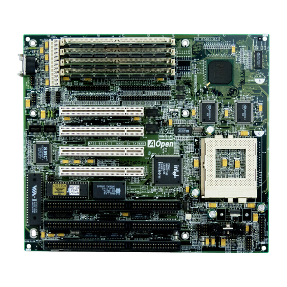
U.S. Environmental Protection Agency (EPA) Energy Star program. The AP53 board measures 220 mm x 250 mm and may come with or without a voltage regulator module (VRM). The VRM enables the board to support future... -
Page 12: Board Layout
Overview Board Layout Power connector 14 Voltage regulator with heatsink SIMM sockets 15 Real-time clock and battery Floppy disk drive connector 16 ISA slots Parallel port connector 17 Keyboard controller Primary IDE connector 18 BIOS Secondary IDE connector 19 Super I/O controller Intel 82439 chip 20 PCI slots Pipelined-burst cache... -
Page 13: Specifications
Overview Specifications Pentium (3.3V) Processor Microprocessor 75/90/100/120/133/150/166/200 MHz 512 MB (maximum) Memory SIMM Sockets 72-pin SIMM x 4 Intel 430HX PCIset ASICs Bus Architecture ISA, PCI Three ISA and four PCI slots Expansion Slots One parallel port (SPP/ECP/EPP) Ports Two serial ports (UART 16C550) Two-channel PCI mode 4 IDE ports (bus master transfer support) One floppy disk drive port... -
Page 14: System Board Parts
Overview System Board Parts 1.3.1 Microprocessor The AP53 system board uses an Intel Pentium (3.3V) processor running at 75, 90, 100, 120, 133, 150, 166, or 200 Hz. Chapter 2 tells how to install and upgrade a Pentium processor. 1.3.2 ASICs The application-specific integrated circuits (ASICs) are the Intel 82439 and Intel 82371 that belong to the Intel 430HX PCIset. -
Page 15: Expansion Slots
1.3.7 Two-channel PCI Mode 4 Enhanced IDE Interface The AP53 board integrates a two-channel PCI mode 4 enhanced integrated drive electronics (E-IDE) interface that allows the system to support four E-IDE devices (including hard disks with more than 528-MB capacity) via two onboard IDE connectors (see section 1.1). -
Page 16: Super I/O Controller
Overview 1.3.8 Super I/O Controller The onboard super I/O controller accommodates the following: Two UART 16450/16550-compatible fast serial ports A parallel port with standard parallel port (SPP), enhanced parallel port (EPP) or extended capabilities port (ECP) support. Both the EPP and ECP comply with the IEEE 1284 standards. -
Page 17: Chapter 2 Hardware Installation
Chapter 2 Hardware Installation This chapter gives you a step-by-step procedure on how to install your system. Follow each section accordingly. ESD Precautions Electrostatic discharge (ESD) can damage your processor, disk drives, expansion boards, and other components. Always observe the following precautions before you install a system component. -
Page 18: Jumper Locations
Hardware Installation Jumper Locations The following figure shows the locations of the jumpers on the system board:... -
Page 19: Setting The Jumper
Hardware Installation Setting the Jumper Set a jumper switch as follows: • To open a jumper, remove the jumper cap. • To close a jumper, insert the plastic Open jumper cap over two pins of a jumper. The conventions in the figure are used to represent the proper jumper settings. -
Page 20: Installing A Microprocessor
Hardware Installation Installing a Microprocessor The motherboard comes with a zero-insertion force (ZIF) microprocessor socket that allows you to install a CPU without using any tool. Follow these steps to install a CPU into a ZIF-type CPU socket: Make sure that the system power is OFF before installing a component. - Page 21 Hardware Installation Attach the heatsink and fan to the CPU. Plug the fan cable onto the two-pin fan connector onboard. The fan connector is marked CN15 on the system board. 2-pin fan power connector (J2)
- Page 22 Hardware Installation Set jumpers JP1 and JP10 CPU FREQUENCY SELECT according to the frequency of the CPU that you install. JP10 75 MHz 90 MHz 100 MHz (default) 120 MHz 133 MHz 150 MHz 166 MHz Set jumper JP11 according to the CPU VOLTAGE SELECT CPU voltage.
-
Page 23: Upgrading The Microprocessor
Hardware Installation Upgrading the Microprocessor To upgrade a CPU: Turn off the system power and remove the housing cover. Locate the CPU socket on the system board. Pull up the socket lever. Remove the installed CPU, if any. Install the upgrade CPU. Refer to section 2.3 for instructions on how to install a CPU. - Page 24 Hardware Installation 16 MB 8 MB 8 MB 20 MB 2 MB 2 MB 8 MB 8 MB 24 MB 4 MB 4 MB 8 MB 8 MB 32 MB 8 MB 8 MB 8 MB 8 MB 32 MB 16 MB 16 MB 36 MB...
-
Page 25: Installing A Simm
Hardware Installation 2.6.1 Installing a SIMM Observe the ESD precautions when installing components. Follow these steps to install a SIMM: Slip a SIMM at a 45° angle into a socket. If the SIMM does not completely fit into the socket, reverse the SIMM orientation. -
Page 26: Removing A Simm
Hardware Installation 2.6.2 Removing a SIMM To remove a SIMM: Press the holding clips on both sides of the SIMM outward to release it. Press the SIMM downward to about a 45° angle. Gently pull the SIMM out of the socket. -
Page 27: Customizing Your Hardware Setup
2.2 for the location of the jumpers on the system board. The following sections tell how to configure the system board to meet the desired performance: 2.7.1 Selecting the Flash ROM Type The AP53 board supports both the 5V JP1301 JP1302 and 12V Flash ROM types. Normally,... -
Page 28: Selecting The Ecp Dma Channel
Hardware Installation 2.7.3 Selecting the ECP DMA Channel The available ECP DMA channel selections are DRQ3/DACK3 and DRQ1/DACK1. The default is DRQ3/DACK3. To select DRQ1/DACK1, reset jumpers JP6 and DRQ3/DACK3 JP7 to 2-3. (default) DRQ1/DACK1 The onboard I/O controller may either be SMC 665 or SMC 669. -
Page 29: Disabling The Ps/2 Mouse Function
Hardware Installation 2.7.5 Disabling the PS/2 Mouse Function The PS/2 mouse function is normally enabled and occupies IRQ12. To reassign IRQ12 to another function, you Enabled need to disable the PS/2 mouse function (default) by opening jumper JP4 and changing the BIOS setup. -
Page 30: Installing The System Board
Hardware Installation Installing the System Board Make sure that you have already installed the system board components like the CPU and memory, and have set the appropriate jumpers before you proceed. Follow these steps to install a system board into a housing: Open the system housing. -
Page 31: Connecting Peripherals
Hardware Installation Connecting Peripherals 2.9.1 Power Cable A standard power supply has two cables with six wires each. Plug these cables to the onboard power connector in such a way that all the black wires are in the center. The power connector is marked CN3 on the system board. -
Page 32: Serial Devices (Com1/Com2)
Hardware Installation Serial Mouse To connect a serial mouse, plug in the serial bracket connectors onto the CN6 and CN7. Insert the serial mouse connector into the appropriate COM port on the bracket. See section 2.9.3. 2.9.3 Serial Devices (COM1/COM2) To support serial devices, insert the serial device connector into the serial port on the bracket. -
Page 33: Printer
Hardware Installation 2.9.5 Printer Plug in the printer bracket connector onto the onboard parallel connector marked CN9 on the board. Refer to the figure. The printer port on the bracket accepts the printer cable. 2.9.6 IDE Devices Primary IDE Connector The primary IDE connector marked CN10 on the system board supports HDD 1... -
Page 34: Front-Panel Switches And Leds
Hardware Installation Secondary IDE Connector The secondary IDE connector is marked CN11 on the board. This connector also supports two IDE devices. To install an IDE CD-ROM drive into your system, insert master port of the secondary IDE cable into the CD-ROM drive connector. If you have more than two hard disks, connect your third hard disk into the master port. -
Page 35: Keyboard
Hardware Installation Speaker Keylock & Power LED Some housings have a five-pin connector for the keylock and power LED. Reset Break Switch Green Mode LED ( Turbo Switch ) ( Turbo LED ) Ground Other housings may have a 12-pin Reset Keylock connector. -
Page 36: Installing Expansion Boards
Hardware Installation 2.10 Installing Expansion Boards Before you install any expansion board, make sure that you have secured the system board in the housing. Follow these steps to install an expansion board: Observe the ESD precautions before removing the expansion board from its protective packaging. -
Page 37: Chapter 3 Ami Bios Utility
Chapter 3 AMI BIOS Utility This chapter tells how to configure the system by setting the BIOS parameters. Entering the AMI BIOS Setup To enter the AMI BIOS Setup, press . The AMI BIOS Setup Main Menu appears as shown below. The AMI BIOS is in Windows form. -
Page 38: Setup Menu
AMI BIOS Utility To select among the options, you can either use the arrow keys to move the highlight bar or simply click on the icon of the desired option. After making your selection, press or double-click on the icon to open the selected menu option. - Page 39 AMI BIOS Utility You can input configuration values such as date, time and disk types in this menu. PRIMARY MASTER AND SLAVE/ SECONDARY MASTER AND SLAVE These parameters allow you to configure the hard disks and the IDE devices connected to your IDE connectors. To configure the hard disk connected to the master port of the primary IDE connector, select Primary Master and press...
- Page 40 AMI BIOS Utility Installed . Select Auto to automatically configure the installed hard CD-ROM CD-ROM disk or IDE device. Select if you have a installed in your system. If you have an old type HDD installed, you may need to enter the HDD parameters manually.
- Page 41 AMI BIOS Utility Block Mode This function enhanced disk performance depending on the hard disk in use. If enabled, it allows data transfers in block (multiple sectors) by increasing the data transfer rate to 256 bytes/cycle. However, if your hard disk does not support this function, set this parameter to This parameter becomes nonconfigurable when the HDD Type parameter is set Auto...
- Page 42 AMI BIOS Utility HARD DISK TYPES After you have set all the necessary parameters, press . A list of the HDD drive parameters appears: Select your hard disk type. Press the to move among the selections. After you have made your selection, press If you cannot find your hard disk drive type on the list, select User .
-
Page 43: Advanced Cmos Setup
AMI BIOS Utility FLOPPY DRIVES A AND B To configure the first floppy drive, select Floppy A . The following values appear on screen: After selecting the proper setting, press Floppy B Select and follow the same procedure to configure the second floppy drive. - Page 44 AMI BIOS Utility Do not change the settings of the Advanced Setup parameters if you are not a qualified technician. Doing so may cause fatal system failure. Quick Boot During boot-up, the system performs power-on self test (POST) routines. Enable the parameter if you want to skip some POST routines during the boot process.
- Page 45 AMI BIOS Utility Boot-up Sequence The boot-up sequence allows you to specify the system search sequence. The selections are C:, A:, CD-ROM / A:, CD-ROM, C: / A:, C:, CD-ROM / C:, CD-ROM, A: / CD-ROM, A:, C: CD-ROM, C:, A:. If you have a bootable CD-ROM installed, you may A:, C:, CD-ROM.
- Page 46 AMI BIOS Utility System Keyboard Present Set this parameter to if there is a keyboard connected to the Absent system. Otherwise, select Primary Display This function detects the type of VGA in use. The selections are VGA/EGA, CGA 40 x 25, CGA 80 x 25, Mono, Absent .
- Page 47 AMI BIOS Utility System BIOS Cacheable Enabling this parameter allows you to change the system BIOS from ROM to RAM. When the system boots, the BIOS routines are copied into the RAM area. This enhances system performance as information access is faster in RAM than in ROM.
-
Page 48: Chipset Features Setup
AMI BIOS Utility 3.2.3 Chipset Features Setup The Chipset Features Setup controls the board chipset settings. The controls for this menu are the same as for the previous screens. The Chipset Features Setup screen appears as follows. To scroll down the rest of the parameters, press . - Page 49 AMI BIOS Utility Memory Hole This option lets you assign the system memory area to avoid memory conflicts. The settings are 512~640K, 15~16M Disabled 8-bit I/O Recovery Time (Sysclk) This parameter allows you to set the response time of the 8-bit I/O devices 1-7 SYSCLK connected to your system.
- Page 50 AMI BIOS Utility cycles on four continues addresses from the DRAM cache. Therefore, it has four settings to adjust. The parameter settings are X-4-4-4, X-3-3-3, X-2-2-2 Faster DRAMs require shorter wait states. The value of depends on the DRAM Lead-off Timing parameter setting. The default is X-4-4-4 DRAM WRITE BURST TIMING This parameter adjusts the write wait state between L2 and DRAM cache.
- Page 51 AMI BIOS Utility Peer Concurrency Enable the parameter to allow the CPU to run secondary DRAM PCI master cycles to target PCI peer devices. Select Disabled to hold the CPU bus. The default setting is Disabled Memory Error Check Mode BIOS automatically detects the memory error check mode supported by the secondary cache installed in your system.
-
Page 52: Power Management Setup
AMI BIOS Utility 3.2.4 Power Management Setup To take advantage of the power-management feature, select Power Management from the Setup menu. The following screen appears: To scroll down the rest of the parameters, press . Use to highlight the desired parameter. 3-16... - Page 53 AMI BIOS Utility Power Management/APM This parameter enables or disables the advanced power-management function. Instant On Timeout (Minutes) This parameter is configurable only if the Power Management/APM parameter is set to Instant On . This lets you specify when to resume system power after being in power-saving mode for a certain period of time.
- Page 54 AMI BIOS Utility Hard Disk Power-down Mode This option lets you set when to “s pin down your IDE hard disk. The disk returns to full speed once the system resumes to normal mode. The available settings are Standby, Suspend Disabled .
-
Page 55: Pci/Pnp Setup
AMI BIOS Utility 3.2.5 PCI/PnP Setup The PCI/PNP Setup allows you to specify the setting for your PCI devices. The screen below appears on screen if you select PCI/PnP from the Setup menu. To scroll down the rest of the parameters, press . - Page 56 AMI BIOS Utility Plug and Play Aware O/S This parameter lets you enable or disable the Plug and Play feature. PCI VGA Palette Snoop PCI devices support the palette snooping technique that enables the device to control access to their palette registers. Enable this parameter to activate the palette snooping function in the PCI VGA devices installed in the system.
- Page 57 AMI BIOS Utility INTD, Hardwired Disabled . If the PCI IDE Card parameter is Auto set to , this parameter becomes nonconfigurable. PCI IDE Secondary IRQ This parameter lets you assign an IRQ for the IDE device connected to your secondary IDE connector.
-
Page 58: Peripheral Setup
AMI BIOS Utility 3.2.6 Peripheral Setup Select Peripheral from the Setup menu and the following screen appears. Onboard FDC This parameter enables or disables the floppy drive controller. Onboard Serial Port 1 This parameter allows you to select the address for the first serial port. Selecting Disabled deactivates the port. - Page 59 AMI BIOS Utility Onboard Parallel Port This parameter allows you to select the address for the parallel port. Selecting Disabled deactivates the parallel port. PARALLEL PORT IRQ This parameter is configurable only if the Onboard Parallel Port is NOT set to Auto .
-
Page 60: Security Setup
AMI BIOS Utility Security Setup The Security window contains the password and anti-virus features. 3-24... -
Page 61: Supervisor Password
AMI BIOS Utility 3.3.1 Supervisor Password The use of password prevents unauthorized use of your computer. If you enabled the Supervisor password, the system prompts for the correct password before granting access to Setup. To set a Supervisor password, select Supervisor from the Security window. -
Page 62: User Password
AMI BIOS Utility Enter the password when a confirmation box appears. 3.3.2 User Password If you enabled the User password, it is impossible to boot the computer and enter Setup without entering the correct password. To set a User password, select User from the Security window. -
Page 63: Utility Setup
AMI BIOS Utility Utility Setup The Utility window lets you change WinBIOS Setup colors and language setting. 3-27... -
Page 64: Color Set
AMI BIOS Utility 3.4.1 Color Set Select Color Set from the Utility window to display the following screen. Use the arrow keys or simply click an option to select your desired background color for WinBIOS. 3.4.2 Language Language Select from the Utility window to display the following screen. The system language currently supported is only English. -
Page 65: Original
AMI BIOS Utility 3.5.1 Original Original When you select , a dialog box prompts you restore the old values. Select to keep your current settings or to restore the original values. 3-29... -
Page 66: Optimal
AMI BIOS Utility 3.5.2 Optimal When you select Optimal , a dialog box prompts you load the optimal values. Select to keep your current settings or to load the optimal values. 3.5.3 Fail-safe When you select Fail-safe , a dialog box prompts you load the fail-safe values. -
Page 67: Ncr Scsi Bios And Drivers
AMI BIOS Utility Use the key then press or simply click on an option to select. Select Save changes and Exit to save the changes that you made. Select Do not save changes and Exit to leave setup without saving Continue your changes. - Page 68 AMI BIOS Utility The system board also supports the AMI Flash Memory Writer Utility that allows you to upgrade the system BIOS. For more information on this utility, contact your local distributor. 3-32...
- Page 69 Appendix A Jumper and Connector Summary CPU Frequency CPU Frequency JP10 75 MHz 1-2, 3-4 1-2, 3-4 90 MHz 1-2, 3-4 100 MHz 1-2, 3-4 * 120 MHz 3-4, 5-6 133 MHz 3-4, 5-6 150 MHz 5-6, 7-8 166 MHz 5-6, 7-8 CPU Voltage CPU Voltage...
- Page 70 Jumper and Connector Summary Flash ROM Type Flash ROM Type JP1301 JP1302 1-2 * Super I/O Controller Super I/O Controller SMC665 Enabled Disabled SMC669 Enabled Disabled ECP DMA Channel Super I/O ECP/DMA Controller Channel SMC665 DRQ3/DACK3 1-2 * 1-2 * DRQ1/DACK1 SMC669 Auto-...
- Page 71 Jumper and Connector Summary PS/2 Mouse Function Enabled Closed Disabled Open Keyboard Clock Clock JP1401 ISA clock 1-2 * 12 MHz Onboard Connectors Connector Function PS/2 keyboard (optional) AT keyboard Power PS/2 mouse header COM2 COM1 Printer/Parallel CN10 IDE1 CN11 IDE2 CN12 HDD LED...
Need help?
Do you have a question about the AP53 and is the answer not in the manual?
Questions and answers