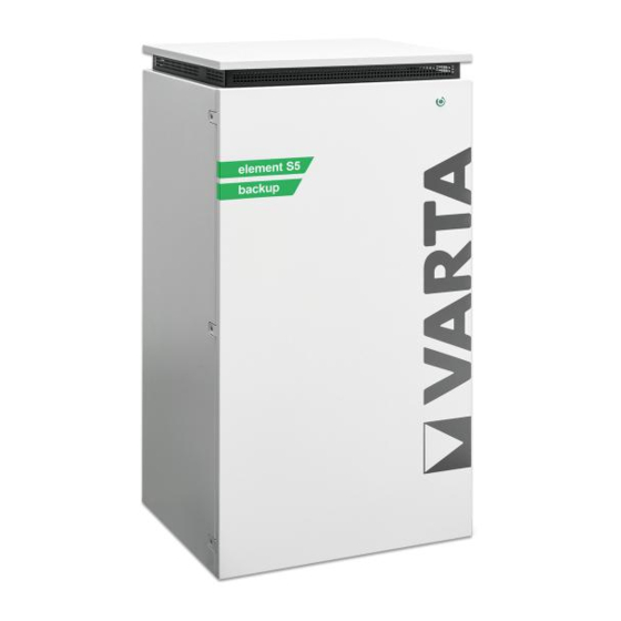
Varta element backup 6 Operating Manual

Varta element backup 6 Operating Manual

Hide thumbs Also See for element backup 6:
Table of Contents

Advertisement

Quick Links

O
PERATING MANUAL
VARTA element backup
VARTA Storage GmbH

Advertisement

Table of Contents
loading

Summary of Contents for Varta element backup 6

  • Page 1 PERATING MANUAL VARTA element backup VARTA Storage GmbH...
  • Page 3 Tel.: +49 9081 24086 6044 Document number: 802970-02 Stand: 10/2021 Note to the electrical specialist This manual contains, in the first part, general information on the operation of the VARTA element backup energy storage system. Installation Operation in the password-protected area...
  • Page 4: Table Of Contents

    5.1.1 Part 1: Installer ..................................26 5.1.2 Part 2: End customer ................................26 OPERATION ........................................ 27 ..............................27 WITCHING ON AND OFF WEB INTERFACE The VARTA element backup ................................ 28 6.1.1 Switching on and off (VARTA element backup) ...................... 28...
  • Page 5 External power reduction ................................42 11.7 Connection plans of the VARTA element backup ......................43 11.7.1 VARTA element backup with replacement power box in the TT network ..........43 11.7.2 VARTA element backup with replacement power box in the TN-C network .......... 44 11.7.3 VARTA element backup in the house installation in the TT network ............
  • Page 6 11.12 Initial start-up ..................................... 64 11.12.1 Check activation of the battery modules ........................64 11.12.2 Password entry ..................................65 11.12.3 Quick Install - basic settings ............................68 11.12.4 Quick Install - network ................................ 69 11.12.5 Quick Install - network ................................. 70 11.13 Checking the system ..................................
  • Page 7 13.10.6 View of the battery charger from behind ........................96 13.10.7 VARTA element backup Install battery charger ..................... 96 13.10.8 Dismounting and installing the battery modules ....................98 13.10.9 Replacing and cleaning the air filter ..........................99 13.10.10 Dismounting the cover of the storage cabinet ....................... 99 13.10.11...
  • Page 8 This manual is part of the system and corresponds to the technical state-of-the-art at the time of publication. It applies to the product VARTA element backup in the expansion stages: 6, 12 and 18 kWh, as of serial number 127XXXXXX (type plate).
  • Page 9: General

    General Information about this manual Symbol explanation The following types of safety directions and tips are used in this operating manual Indicates tips regarding use of the device. Safety instructions In this manual, the safety directions are structured as follows: Signal word Type and source of danger! Possible consequence(s) in the event of non-compliance.
  • Page 10: General Safety Signs

    General safety signs Symbol Meaning Prohibition signs are round, with a black pictogram, on a white background and a red border and crossbar. Prohibition signs are round, with a white symbol, on a blue background. Warning signs are triangular, with a black symbol and border, on a yellow background.
  • Page 11: Safety

    In the event of a power failure, the replacement power function of the VARTA element backup is to enable the supply of selected consumers in the household. The technical parameters described in chapter 3.8 from page 20 indicate the efficiency of the store.
  • Page 12: Erroneous Use

    WARNING Insufficient qualification of the electrical specialist. Personal and material damage. Activities on the VARTA element backup system (e.g. installation and maintenance work) may be performed by qualified electrical specialists certified by VARTA Storage only. Here, specialists refers to persons who, among other things, possess the knowledge of relevant terms and skills.
  • Page 13: General Danger Sources

    General danger sources If the following directions on handling the device are not complied with, this can lead to personal damage and material damage to the device for which VARTA Storage GmbH assumes no liability. 2.7.1 Danger due to electrical voltage DANGER Contact with electrical voltage.
  • Page 14: Danger Due To Heat

    2.7.4 Danger due to heat ATTENTION Insufficient ventilation of the system! Overheating of the system possible. Keep vents clear. Ensure sufficient ventilation. ATTENTION Heat entry due to direct solar radiation or devices that emit heat! Overheating of and damage to the system possible. Protect system from direct solar radiation.
  • Page 15: Safety Equipment

    VARTA. The VARTA element backup energy storage system has several pieces of safety equipment. These include grid and system protection according to VDE-AR-N 4105, closed electrical operating area, overtemperature switch- off and a door switch.
  • Page 16: Function, Scope Of Delivery And Technical Parameters

    In the process, the batter converter in the VARTA element backup system converts the alternating current into direct current and charges the battery modules. If the maximum charging capacity is reached or if the solar-produced electricity exceeds the maximum charging current, the excess solar power is fed into the public network.
  • Page 17: Cascade Mode

    The replacement power function of the VARTA element backup is not an uninterrupted power supply (UPS) or safety power supply. Note: Before installation of the VARTA element backup, it must be clarified with the respective energy supply company whether it is necessary to register the system.
  • Page 18: View Of The Varta Element Backup

    View of the VARTA element backup Description Description Cover Screws for opening the door Type plate Black start button On/off switch Ventilation grid...
  • Page 19: System Overview Own Consumption Optimisation

    System overview Own consumption optimisation This system overview shows the classic use of a VARTA element backup for own consumption optimisation. The replacement power function is not used here. Description Description Photovoltaic system Consumers in the household Converter for photovoltaic system...
  • Page 20: System Overview With Replacement Power Consumers

    System overview with replacement power consumers This system overview shows the layout of a VARTA element backup system with connected replacement power consumers. In the event of a power failure, the consumers shown in (5) are supplied by the storage system.
  • Page 21: Identification

    Identification 3.7.1 Type plate 3.7.2 ID label of the battery module...
  • Page 22: Technical Parameters Varta Element Backup

    Technical parameters VARTA element backup Expansion stages Nominal capacity (kWh) 13.0 19.5 Integrated network operation AC charging power (kW) AC discharging power (kW) Batter converter layout without isolating transformer Grid connection 400 V AC, 3-phase, 50 Hz Inrush current < max. operating current for input and output...
  • Page 23: Battery Module

    Derating means a temporary curtailment of the maximum performance of the battery converter in order to prevent components from being heated excessively. VARTA energy storage systems are designed in such a way that when the operating and environmental conditions are complied with the permitted operating temperature is not exceeded and a derating is not necessary.
  • Page 24: Replacement Power Operation Varta Element Backup

    Do not connect any cooling equipment to the energy store. In the event of a power failure, the VARTA element backup automatically switches to the replacement power mode. Thus, it is possible to continue to operate selected consumers. •...
  • Page 25: Electrical Consumers In The Replacement Power Operation

    For devices that are to be connected to the replacement power network of the VARTA element backup, the inrush current is limited to 12 A. Here, the total of all connected consumers is to be taken into account.
  • Page 26: Black Start

    Test the function by switching off the fuse in the supply line of the store (compare chapter 11.7: “Connection plans of the VARTA element backup”, beginning on page 43; “F1”). The store will build up the replacement power network automatically within the defined switchover time and supply the connected consumers.
  • Page 27: Activate Replacement Power Function

    At the same time, however, the capacity reserved for a power failure is smaller. Guarantee For the guarantee to become effective, the following data must be held by VARTA Storage: • Serial number (SN number) of the VARTA system, •...
  • Page 28: Guarantee Registration

    5.1.1 Part 1: Installer installer Registration of the energy store by the • Launch the page: https://b2b.varta-storage.com/nc/b2b.html • Enter all the necessary data 5.1.2 Part 2: End customer installer has registered the energy store. You can carry out the guarantee registration once the •...
  • Page 29: Operation

    Operation Switching on and off, web interface DANGER Contact with electrical voltage. Danger to life due to electric shock. Always keep the energy store closed. Look out for damage to the electrical equipment. Have defects eliminated immediately. Only the electrical specialist is allowed to open the energy store. The energy store may be opened only while switched off.
  • Page 30: The Varta Element Backup

    Switching on and off (VARTA element backup) The VARTA element backup is started up using the on/off switch (3). Here, it should be taken into account, however, that the replacement power connection is also supplied with voltage from the mains when switched off.
  • Page 31: The Web Interface

    The web interface The web interface serves to visualise the current measured values as well as to configure settings and on the software-side functions. In the following, the necessary steps for the initial start-up are explained. As a condition, the energy store must be installed according to the operating manual and the initialisation must have been successful.
  • Page 32: The Energy Manager

    Network (RJ45 socket) Wall fastening • Enter the serial number of the energy storage system in the address bar in your browser after http://varta. For example: http://varta127023456. You will find the serial number on the type plate on the outside of the energy store.
  • Page 33: The Portal

    In the event that an online guarantee is concluded, a permanent internet connection must be ensured. Access to the portal is activated as soon as you agree to the VARTA online services as part of the guarantee registration.
  • Page 34: Maintenance And Cleaning

    Maintenance and cleaning WARNING Improper performance of maintenance and cleaning works. Possible danger to life. Ensure that an electrical specialist carries out the maintenance and cleaning works. Only original parts are to be used for maintenance works. Maintenance works The maintenance of the energy storage system includes: •...
  • Page 35: Fault

    Fault WARNING Improper elimination of faults. Possible danger to life. Ensure that an electrical specialist performs the works on the energy store. In the event of a fault, contact the electrical specialist. Fault displays 8.1.1 Fault displays of the LED ring on the on/off switch The LED ring of the on/off switch on the front of the cabinet displays faults.
  • Page 36: Case Of Damage

    Case of damage Behaviour in the event of damage WARNING Improper action in the case of fire and flooding. Possible danger to life. If possible, switch off the system and fuses. Leave the danger area. In the event of a fire, inform the fire brigade immediately. Inform the fire brigade that there are lithium-ion batteries in the energy storage system.
  • Page 37: Installation

    Installation This section is directed towards the electrical specialist. 10 Transport and storage 10.1 Transport Lithium-ion batteries are dangerous goods. The battery modules are designed and tested in such a way that they may be transported up to a total weight of 333 kg under compliance with the conditions of ADR 1.1.3.6 (not transport requiring labelling provided there are no other dangerous goods on or in the vehicle).
  • Page 38: Packaging/Transport Control

    Danger to life. Do not accept clearly damaged packaging. Contact VARTA. The storage cabinet and the battery module (individually packed) are delivered in separate and tested packaging units on pallets. The installer assumes the disposal of the packaging. Please check the deliveries for completeness and damage: •...
  • Page 39: Storage

    To identify improper handling during transport, a ShockWatch® sticker is attached on the outside of the cardboard packaging of the storage cabinet. If the impact indicator shows the colour red, the shipment was exposed to strong shaking. • The storage cabinet is possibly damaged. •...
  • Page 40: 11 Assembly And Installation

    Short circuit and corrosion due to condensation water. Begin with the assembly only when the components have taken on room temperature. WARNING Installation of damaged components! Possible danger to life. Check all components for visible damage. Do not install damaged components. Contact VARTA.
  • Page 41: Setup Site Requirements

    20. • If appropriate, have the statics checked. The subsurface, connecting walls and ceilings must not consist of heart-sensitive materials. • A smoke detector must be installed in the setup room of the VARTA element backup.
  • Page 42: Environmental Conditions

    The distance to adjacent installations must be approximately 5 cm to the right and approximately 10 cm to the left. A space of approx. 120 cm in depth in front of the device is required to be able to perform installation and maintenance work via the front door.
  • Page 43: Preparation Of The Electrical Connection

    11.5 Preparation of the electrical connection This section is directed towards the electrical specialist. DANGER Contact with electrical voltage. Danger to life due to electric shock. Switch off the replacement power circuit. Switch off connected generation systems. DANGER Switching off the supply line of the store can activate the replacement power mode.
  • Page 44: External Power Reduction

    Therefore, according to the country-specific specifications, the installation of a switch- off mechanism may be necessary. The VARTA element backup supplies potential-free binary inputs for power reduction and switch-off for the external active power switch-off. When installing, pay attention to the short guide on external power reduction (LINK or QR code.
  • Page 45: Connection Plans Of The Varta Element Backup

    The regulations of the country-specific standards, such as DIN VDE 0100, are to be complied with. Meter concepts are to be coordinated with the electricity grid operator. 11.7.1 VARTA element backup with replacement power box in the TT network Q2 Residual current device type B I∆n 30 mA F2 Circuit breaker 6 A type B Three sockets for consumers entitled to replacement power To prevent electrical accidents: Label the distributor for the replacement power.
  • Page 46: Varta Element Backup With Replacement Power Box In The Tn-C Network

    11.7.2 VARTA element backup with replacement power box in the TN-C network Q2 Residual current device type B I∆n 30 mA F2 Circuit breaker 6 A type B Three sockets for consumers entitled to replacement power To prevent electrical accidents: Label the distributor for the replacement power.
  • Page 47: Varta Element Backup In The House Installation In The Tt Network

    11.7.3 VARTA element backup in the house installation in the TT network Q2 Residual current device type B I∆n 30 mA F2 Circuit breaker 6 A type B Output terminal for consumers entitled to replacement power To prevent electrical accidents: Label the distributor for the replacement power.
  • Page 48: Varta Element Backup In The House Installation In The Tn-C Network

    11.7.4 VARTA element backup in the house installation in the TN-C network Q2 Residual current device type B I∆n 30 mA F2 Circuit breaker 6 A type B Output terminal for consumers entitled to replacement power To prevent electrical accidents: Label the distributor for the replacement power.
  • Page 49: Network Connection Preparation (Black Plug)

    11.8 Network connection preparation (black plug) For the network connection, the 5-wire network connection line must be connected to the plug connection (black plug) provided • Strip the connection line 40mm at the end. • The PE conductor must be 5mm longer than the other four conductors (L1, L2, L3, N). Shorten these conductors accordingly.
  • Page 50 Description brown black grey blue green-yellow • Introduce the wires into the screw connections in the contact insert and tighten. Ensure that the conductors are securely fixed in the connections. • Introduce the contact insert into the plug housing. Both parts must audibly latch into each other with the side detents.
  • Page 51: Replacement Power Connection Preparation (Light Grey Plug)

    11.8.1 Replacement power connection preparation (light grey plug) For the replacement power connection, the 5-wire replacement power connection line must be connected to plug connection (light-grey plug) provided. • Strip the connection line 40mm at the end. • The PE conductor must be 5mm longer than the other four conductors (L1, L2, L3, N). Shorten these conductors accordingly.
  • Page 52: Connecting The Varta Split Core Current Sensor

    For the position of the “current measurement” socket on the energy storage system, see Figure 3: Back of storage cabinet on page 52. Figure 3: Back of storage cabinetFor the VARTA Split Core current sensor to record the consumption and feed- in performance correctly, the following must be complied with:...
  • Page 53: Connecting The Optional Current Sensor

    Folding transducers (L1, L2, L3) To mount the folding transducer on the VARTA Split Core current sensor, the conductor must be placed through the opening of the blue folding transducer. To this end, open the locking mechanism on the back, place the folding transducer around the conductor and close it.
  • Page 54: Assembly Preparation

    11.10 Assembly preparation This section is directed towards the electrical specialist. Read the operating manual. WARNING Components are heavy. This can lead to overburdened intervertebral discs, contusions and strains. Carry out the works described in this chapter with 2 persons or suitable aids. At the setup site, tilt cabinet maximum 30°...
  • Page 55 • without battery module Position the energy store at the setup site. • Mount the power connector (black) onto the port (1). The closure locks in audibly. • Mount the replacement power connector (light grey) onto the port (2). The closure locks in audibly. •...
  • Page 56: Battery Module Assembly

    11.11.2 Opening the storage cabinet The VARTA element backup is shut down using the on/off switch (3). Here, it should be taken into account, however, that the replacement power connection is also supplied with voltage from the mains when switched off.
  • Page 57: Check The Battery Modules

    Do not attempt a repair! Avoid contact with any escaping liquid! Avoid contact with any escaping vapours! Damaged or soiled battery module Contact VARTA. First aid in the event of contact with escaping liquid If inhaled: • Leave the room.
  • Page 58: Fit And Connect Battery Modules

    11.11.5 Fit and connect battery modules WARNING Improper handling of battery module. Personal and material damage. Carry out the works described in this chapter with 2 persons or suitable aids. Do not lift the battery module using the handle. Hold the battery module by the handle when fitting it. ATTENTION Two battery modules on one battery charger.
  • Page 59: Connections On The Battery Module

    11.11.6 Connections on the battery module Designation DRY contact LED display Activation button Connections for battery current Designation Farbe Colour Couleur Colore Fault lila purple pourpre porpora Warning grau grey gris grigio 11.11.7 Connections on the battery charger (front) Designation Directions and warnings Battery current 1 Do NOT use - battery current 2...
  • Page 60: Position Of The Battery Modules

    11.11.8 Position of the battery modules Depending on the model, up to three battery modules are integrated. • The first battery module (11) is mounted on the back wall of the energy store. Designation Converter Battery charger 1 (BL 1) Battery charger 2 (BL 2) Battery charger 3 (BL 3) 2 fastening screws per battery module right...
  • Page 61: Element 6 - Fit And Connect Battery Module

    11.11.9 Element 6 - Fit and connect battery module Figure 4: Battery charger 1 - battery module 1 Figure 5: Battery charger 1 – back violet Cable of converter with inscription and 1 x colour: Mounting the battery module • Battery module 1 (BM 1) is positioned behind, on the back wall of the storage cabinet.
  • Page 62: Element 12 - Fit And Connect Battery Modules

    11.11.10 Element 12 - Fit and connect battery modules Figure 6: Battery chargers 1 and 2, battery modules 1 and 2 Figure 7: Battery charger 1 and 2 back violet Cable of converter with inscription and 1 x colour: orange Connect the cable of converter 1 x colour: to the battery charger 2 (BC 2) Battery charger 1 must NOT be bridged with battery charger 2 and/or battery charger 3!
  • Page 63 a. Battery current connection (no. 5): • Pay attention to the polarity. • Insert the two plugs. b. Communication (no. 1): • Pay attention to the pin assignment. • Insert the four communication cables into the openings of the clamping connector. •...
  • Page 64: Element 18 - Fit And Connect Battery Modules

    11.11.11 Element 18 - Fit and connect battery modules Figure 8: Battery chargers 1 and 2, battery modules 1, 2 and 3, Figure 9: Battery chargers 1, 2 and 3 back violet Cable of converter with inscription and 1 x colour: orange Connect the cable of converter 1 x colour: to the battery charger 2 (BC 2)
  • Page 65: Closing The Storage Cabinet

    Mounting battery module 2 • Battery module 2 (BM 2) is positioned in front of battery module 1 (BM 1). Mounting battery module 3 • Battery module 3 (BM 3) is positioned in front of battery module 2 (BM 3). First create the connection between battery charger 1 (BL 1) and battery module 1 (BM 1).
  • Page 66: Initial Start-Up

    11.11.9 beginning on page 59, chapter 11.11.10 beginning on page 60 and chapter 11.11.11 beginning on page 62. The following steps are required for switching on the VARTA element backup energy storage system: •...
  • Page 67: Password Entry

    Connect your PC/notebook to the customer’s network. • Enter the serial number of the energy storage system in the address bar in your browser after http://varta. For example: http://varta127023456. You will find the serial number on the type plate on the outside of the energy store.
  • Page 68 Description Field for entering the password Language selection Network supply Internet connection to the VARTA server (green = online, red = offline). Information Charging status Operating status Operation Productivity performance Energy consumption • password Enter your password in field (1)
  • Page 69 Further buttons appear in the header. Quick Install After the initial installation, it is necessary to carry out the in the interface Description Version Quick Install Logout Settings System • Quick Install Actuate the button (2) in the header. • Next To carry out the assistant, actuate the button (1).
  • Page 70: Quick Install - Basic Settings

    11.12.3 Quick Install - basic settings Description Device name entry maximum 20 characters Date entry Time entry Time zone entry Selection automatic switchover summer- wintertime Checkbox active / inactive Selection store type Radio button active / inactive Serial number entry battery modules 1 to 3 Back / Cancel / Next •...
  • Page 71: Quick Install - Network

    11.12.4 Quick Install - network Description Activate DHCP Checkbox active / inactive Back / Cancel / Next As standard, the store assumes the settings of the customer network. Activate DHCP To this end, the choice box beside (1) is ticked as a factory setting. Should the connection not take place automatically, take the parameters from the manual of the network router.
  • Page 72: Quick Install - Network

    90 seconds. If the LED ring continues to flash red after the restart (duration approximately 3 minutes): Check the connection to the current sensor and the phase assignment. Should the LED ring continue to flash red, contact VARTA.
  • Page 73: Checking The System

    11.13 Checking the system Once the energy storage system has been set up and connected, various system parameters must be checked. 11.13.1 Check on the homepage Description Home button Info button • Home Click on the button (1). • Info Click on the button (2).
  • Page 74: Checks On The System Page

    11.13.2 Checks on the system page • System Click on the button in the header. expansion stage of the energy store software update Note: According to the and after a , the website can deviate from the following image. Description Battery charger overview Batter converter overview Battery module serial number overview...
  • Page 75: Checking The Connections On The Battery Converter

    11.13.3 Checking the connections on the battery converter • Check whether the system reports a current flow (realistic currents) on all three phases. There is a fault if the value for the current (I network) oscillates between +0.01 and ­0.01 on all three phases. Check the cable connection to the current sensor.
  • Page 76: Leaving The Password-Protected Area

    11.15.1 Leaving the password-protected area Finally, it must be ensured that the customer does not have access to the password-protected area. • Click on Logout...
  • Page 77: Operation In The Password-Protected Area

    Operation in the password-protected area This section is directed towards the electrical specialist. 12 The password-protected area 12.1 Access to the password entry web interface Some parameters may be changed only by trained and qualified personnel and not by the operator! The access to the web interface is described in chapter 6.3 “The web interface”, beginning on page 29.
  • Page 78: The System Menu

    You now have access to further menu items, which are explained in the following chapters. • System Click on the button. 12.2 The system menu This page shows you a current overview of the battery chargers (1), the data of the battery converter (2), the serial numbers of the battery modules (3), current system faults and network errors (4) and the status of the battery modules (5).
  • Page 79: The Version Menu

    12.3 The version menu This page shows you the versions of the system components.
  • Page 80: The Settings Menu

    12.4 The settings menu Settings From the page, you have access to further input masks. Description Basic settings Network Service settings Mains Factory settings Reset 12.4.1 Basic settings On this page, basic settings can be changed: Device name: Entry at initial start-up. A maximum of 20 characters are available. Date and time can be entered here.
  • Page 81: Network/Portal Connection

    Reset air filter change time: The time until the next air filter change can be reset. To this end, tick the choice box. A condition is that the air filter is actually replaced or cleaned. Checking the current sensor: Upon consultation with VARTA Service, the automatic current sensor check can be disactivated.
  • Page 82: Network

    12.4.5 Network • The network parameters of the frequency-dependent active power adjustment P(f) and the grid and plant protection must be adapted to the requirements of the respective country. • Change the settings - if necessary. Note: The change of network-relevant parameters must be approved by the electricity grid operator. Description Country ID Network parameters...
  • Page 83 12.4.5.2 Manual entry • Manual entry Select in the drop-down list. under-excited over-excited You can set the target value for cos(phi) between 0.9 and 0.9 . To this end, select the desired value in the drop-down list. Power factor set value Target value for cos(phi) 0.90 -100...
  • Page 84 12.4.5.3 Setting according to Q(P) characteristic • Q(P) characteristic Idle power function: Select the in the drop-down list. QPX1 QPX2: Enter the set values for QPX1 and QPX2 using the number entry fields. Take the set values from Figure 4: Q(P) characteristic. QPY1 QPY2: Enter the set values for QPY1 and QPY2 using the number entry fields.
  • Page 85: Setting According To Q(U) Characteristic

    12.4.6 Setting according to Q(U) characteristic • Q(U) characteristic Select the in the drop-down list. QUX1 to QUX4: Enter the set values for QUX1 to QUX4 using the number entry fields. Take the set values from Figure 4: Q(P) characteristic. QUY1 to QUY4: Enter the set values for QUY1 to QUY4 using the number entry fields.
  • Page 86: The Power Restriction Menu

    Current mains voltage in % under-excited over-excited Figure 11: Q(U) characteristic 12.5 The power restriction menu If you require the power restriction P(U) (GATE generator), you can choose between characteristic A and B via the drop-down list. 12.6 Leaving the password-protected area Finally, it must be ensured that the customer does not have access to the password-protected area.
  • Page 87: Maintenance

    Maintenance 13 Basic information on maintenance. This section is directed towards the electrical specialist. 13.1 Safety instructions DANGER Touching live parts. Danger to life. Comply with a waiting time of at least 3 minutes. Ensure that the battery modules are switched off and that no LED display is lit The energy store must not be transported if a battery module is already integrated.
  • Page 88: Scope Of The Maintenanceworks

    Only original parts are to be used for maintenance works. After all the works, the connections are to be created cleanly again and screwed. All works on the VARTA element backup system are to be documented by the electrical specialist. WARNING Touching sharp-edged parts! Cut injuries.
  • Page 89: External Check Of The Storage Cabinet

    , the website can deviate from the following image. 13.5.1 Checking the online status WWW symbol On the homepage of the web interface, the (1) displays whether the energy storage system has a connection to the VARTA server (green = online, red = offline).
  • Page 90: Error Lists

    If necessary, check the grid and plant settings (see chapter 12.4.5 on page 80) and remove the faults. • Then restart the store. To this end, switch the store “OFF” at the on/off switch and then “ON” again. If the faults cannot be eliminated, inform VARTA Service. Report In the case of stores operated offline, click the...
  • Page 91: Check Software Version

    13.5.4 Check software version In the version overview, you can read out the software versions. • Version Select the button in the header. 13.5.5 Air filter change: Reset time Settings Service The air filter must be replaced at every second service. Under the button, select the item settings Settings...
  • Page 92: Check Ventilator

    13.5.6 Check ventilator • Settings Service settings Under the button, select the item • Manual ventilator activation Under , change between the stages 0 (Automatic), 1 (medium stage) and 2 (highest stage). Settings Basic settings Network Service settings Service settings Network parameters Idle power compensation Power restriction...
  • Page 93: Checking The System Parameters

    13.6 Checking the system parameters The system parameters are checked via the web interface. • Select the System page. Description Battery charger overview Batter converter overview Battery module serial number overview Error list / grid and plant error list Battery modules - battery chargers overview 13.6.1 Checking the current sensor values •...
  • Page 94: Measures In The Event Of Conspicuous Current Sensor Values

    13.6.2 Measures in the event of conspicuous current sensor values: If, despite the charge, the current sensor value of one or several phases is 0, check the connection between the energy storage system and the current sensor. • If necessary, replace the connection line. •...
  • Page 95: Service And Repair: Cabinet Interior

    13.10 Service and repair: Cabinet interior This section is directed towards the electrical specialist. DANGER Touching live parts. Danger to life. Switch off the store. Comply with a waiting time of at least 3 minutes. Ensure that the battery modules are switched off and that no LED display is lit The energy store must not be transported if a battery module is already integrated.
  • Page 96: Opening The Cabinet

    13.10.1 Opening the cabinet The VARTA element backup is shut down using the on/off switch (3). Here, it should be taken into account, however, that the replacement power connection is also supplied with voltage from the mains when switched off. Thus, consumers connected to the replacement power connection are also supplied when the store is switched off.
  • Page 97: Dismounting And Installing The Battery Charger

    • both hands Pull the battery converter out with the handles using • Release the plug connections and note the positions. • To reinstall the battery converter, carry out the work steps in reverse order. Note: Only converters of type F, material number 727687, may be used. For the documentation of the maintenance, see chapter 18 on page 106.
  • Page 98: Connections On The Battery Charger Front

    View of the battery charger from behind 13.10.7 VARTA element backup Install battery charger To reinstall the battery converter, carry out the work steps in reverse order. The battery charger locks into the end position. It is not necessary to use a screwdriver.
  • Page 99 Figure 15: Battery charger 1 and 2 back violet Cable of converter with inscription and 1 x colour: orange Connect the cable of converter 1 x colour: to the battery charger 2 (BC 2) Battery charger 1 must NOT be bridged with battery charger 2 and/or battery charger 3! Figure 16: Battery chargers 1, 2 and 3 back violet Cable of converter with inscription and 1 x colour:...
  • Page 100: Dismounting And Installing The Battery Modules

    13.10.8 Dismounting and installing the battery modules WARNING Improper handling of battery module. Personal and material damage. Do not damage the battery module when dismounting and installing it. Do not attempt a repair. Battery modules are maintenance-free and must not be opened under any circumstances.
  • Page 101: Replacing And Cleaning The Air Filter

    13.10.9 Replacing and cleaning the air filter • Unscrew the filter holder. Aid: Torx 25 screwdriver The air filter can be removed. • Clean the filter area with a cloth. • If necessary, clean the air filter with a vacuum cleaner. •...
  • Page 102: Cleaning Or Replacing The Ventilator

    13.10.11 Cleaning or replacing the ventilator WARNING Protective conductor not connected and attached. Personal and material damage. Restore the protective conductor connection. Attach the protective conductor cable. The ventilator is accessible after the cover is dismounted. • Check the ventilator for soiling and clean it if necessary •...
  • Page 103: Completing The Service And Repair Works

    13.11 Completing the service and repair works DANGER Contact with electrical voltage. Danger to life due to electric shock. Switch off the replacement power circuit. Switch off connected generation systems. DANGER Switching off the supply line of the store can activate the replacement power mode. Danger to life due to electric shock.
  • Page 104: Check Operating Status

    13.11.1 Check operating status • Ensure that there is no soiling or material residues in the device interior. • Clean with a vacuum cleaner or similar if necessary. • Switch the battery module(s) on again. • Close and screw the door. •...
  • Page 105: 14 Faults

    14 Faults This section is directed towards the electrical specialist. WARNING Improper fault elimination due to lack of specialist knowledge. Personal and material damage. Only the electrical specialist is allowed to eliminate faults. 14.1 Faults displays of the LED ring The LED ring of the on/off switch on the front of the cabinet displays faults.
  • Page 106: Carry Out Dismount

    Disposal The VARTA element backup system must not be disposed of via the house waste. The packed battery modules are collected by VARTA or by a company mandated by it. To this end, please contact VARTA (entsorgung@varta-storage.com). If necessary, request the dangerous goods packaging from there as well. VARTA shall assume the costs for packaging and collection.
  • Page 107: Carrying Out A Move

    The battery modules are to have a charging status of 20 to 30% of their capacity. If necessary, charge or discharge the battery modules. The battery modules must be recommissioned by a qualified electrical specialist certified by VARTA within 11 weeks after the dismount. Commissioning after a move takes place as described in chapter 8.
  • Page 108: 17 Spare Parts

    With the documentation of the service and maintenance works, you prove that the specified maintenance intervals have been complied with, exclusively original parts have been used and the works on your VARTA element backup storage system have been performed exclusively by qualified electrical specialists certified by VARTA Storage GmbH.
  • Page 109: Service Works

    18.1 Service works Customer data: Surname, first name Address Country - post code and town/city Telephone number Email Store location (if different): Address Country - post code and town/city Installation of energy storage system: Serial number Date Certified service employee Signature/seal Service works* Comments...
  • Page 110: Repair / Other Works

    18.2 Repair / other works Customer data: Surname, first name Address Country - post code and town/city Telephone number Email Store location (if different): Address Country - post code and town/city Installation of energy storage system: Serial number Date Certified service employee Signature/seal Software status: Works performed:...
  • Page 111: 19 Appendix

    Conformity with the EU directives relevant to the device is confirmed by the CE sign. Declaration of conformity (DoC) VARTA Storage GmbH declares that the retrofitting of the VARTA element backup is in accordance with the applicable directives 2014/30/EU and 2014/35/EU. You will find the complete declaration of conformity on our website: www.varta-storage.com.

Table of Contents