
Related Manuals for Waters 3100


Summary of Contents for Waters 3100
- Page 1 Waters 3100 Detector Operator’s Guide 71500135102 Revision E Copyright © Waters Corporation 2006–2010 All rights reserved...
-
Page 2: Copyright Notice
Corporation assumes no responsibility for any errors that may appear in this document. This document is believed to be complete and accurate at the time of publication. In no event shall Waters Corporation be liable for incidental or consequential damages in connection with, or arising from, its use. -
Page 3: Customer Comments
Contacting Waters ® Contact Waters with enhancement requests or technical questions regarding the use, transportation, removal, or disposal of any Waters product. You can reach us via the Internet, telephone, or conventional mail. Waters contact information Contacting medium Information... -
Page 4: Safety Considerations
Considerations specific to the 3100 Detector Solvent leakage hazard The source exhaust system is designed to be robust and leak-tight. Waters recommends you perform a hazard analysis, assuming a maximum leak into the laboratory atmosphere of 10% LC eluate. - Page 5 High temperature hazard To avoid burn injuries, avoid touching the source enclosure Warning: with your hand when operating or servicing the instrument. 3100 Detector high temperature hazard Source enclosure assembly PO W ER O PER ATE NEBULIZER NEBULIZER DESOLVATION DESOLVATION...
- Page 6 High voltage hazard Warning: • To avoid electric shock, do not remove the 3100 Detector’s protective panels. The components they cover are not user-serviceable. • To avoid non-lethal electric shock, any equipment connected to the ESI and IonSABRE™ APCI probes must be grounded.
-
Page 7: Operating This Instrument
Consult instructions for use Intended use Waters designed the Single Quad (3100) Detector for use as a research tool to deliver authenticated mass measurement in MS mode. The Single Quad (3100) Detector is for research use only and is not intended for use in diagnostic applications. -
Page 8: Quality Control
When calibrating mass spectrometers, consult the calibration section of the operator’s guide for the instrument you are calibrating. In cases where an overview and maintenance guide, not operator’s guide, accompanies the instrument, consult the instrument’s online Help system for calibration instructions. -
Page 9: Ism Classification
Class A products are suitable for use in commercial (that is, nonresidential) locations and can be directly connected to a low voltage, power-supply network. EC authorized representative Waters Corporation (Micromass UK Ltd.) Floats Road Wythenshawe Manchester M23 9LZ United Kingdom... -
Page 11: Table Of Contents
Copyright notice ....................ii Trademarks ......................ii Customer comments .................... iii Contacting Waters ....................iii Safety considerations ..................iv Considerations specific to the 3100 Detector ............ iv Safety advisories ....................vi Operating this instrument ................vii Applicable symbols ................... vii Intended use...................... vii Calibrating ...................... - Page 12 Vacuum system ....................1-8 Rear panel ......................1-8 IntelliStart Fluidics system ................1-10 Overview......................1-10 System operation ................... 1-11 2 Preparing for Operation ..............2-1 Starting the instrument .................. 2-2 Configuring IntelliStart................... 2-4 Verifying the instrument’s state of readiness ..........2-4 Tuning and calibration information ...............
- Page 13 4 Optional APCI Mode of Operation ............. 4-1 Atmospheric pressure chemical ionization ..........4-2 IonSABRE APCI probe ..................4-2 Installing the IonSABRE APCI probe ............4-3 Installing the corona pin ................. 4-6 Removing the corona pin ................4-6 Removing the IonSABRE APCI probe ............4-7 5 Maintenance Procedures ..............
- Page 14 Cleaning the sample cone and gas cone ............ 5-19 Removing the cone gas assembly from the source ........5-19 Disassembling the cone gas assembly ............5-22 Cleaning the sample cone and gas cone............5-23 Assembling the cone gas assembly ............... 5-26 Fitting the cone gas assembly to the source..........
- Page 15 Warning symbols ....................A-2 Task-specific hazard warnings................ A-2 Specific warnings ..................... A-3 Caution symbol ....................A-5 Warnings that apply to all Waters instruments ......... A-5 Electrical and handling symbols ..............A-11 Electrical symbols ..................A-11 Handling symbols ..................A-12 B External Connections ................B-1 External wiring and vacuum connections ..........
- Page 16 Connecting the nitrogen exhaust line ............B-20 Connecting the liquid waste line ............... B-23 Connecting the workstation ................ B-25 Connecting Ethernet cables ................ B-26 I/O signal connectors ..................B-26 Signal connections ..................B-28 Connecting to the electricity source ............B-31 C Materials of Construction and Compliant Solvents .....
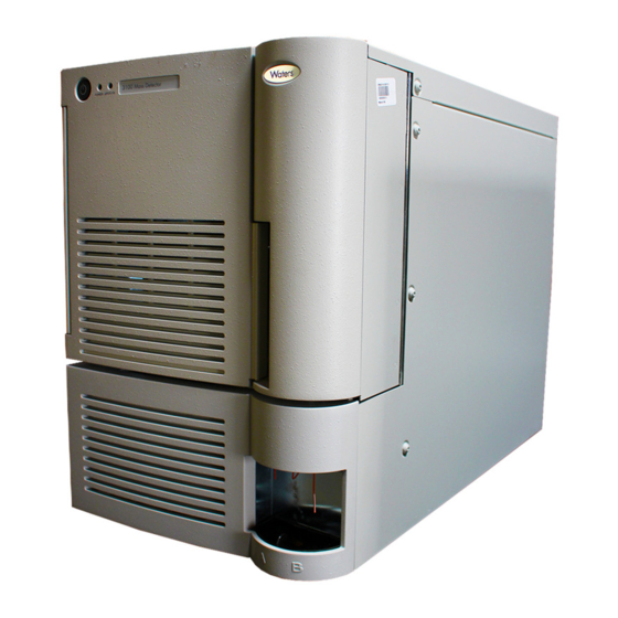
- Page 17 Waters 3100 Detector This chapter describes the instrument, including its controls and gas and plumbing connections. Contents Topic Page Overview Ionization techniques and source probes Ion optics MS operating modes Sample inlet Vacuum system Rear panel IntelliStart Fluidics system 1-10...
-
Page 18: Waters 3100 Detector
(APCI) and electrospray ionization (ESI). Optional ionization modes are IonSABRE™ APCI and APPI (atmospheric pressure photoionization). For instrument specifications, see the Waters 3100 Detector Site Preparation Guide. Waters 3100 Detector TP02592 Waters 3100 Detector... -
Page 19: Overview
Waters 3100 Detector, with doors open PO W ER O PER ATE DESOLVATION DESOLVATION NEBULIZER NEBULIZER APPI APPI PROBE PROBE IntelliStart technology IntelliStart™ technology monitors LC/MS performance and reports when the instrument is ready for use. The software automatically tunes and mass calibrates the instrument and displays performance readbacks. -
Page 20: Waters 3100 Detector
• Monitoring the run. • Acquiring data. • Processing data. • Reviewing data. • Printing data. See Empower and MassLynx 4.1 user documentation and online Help for more information on installing and using Empower or MassLynx software. Waters 3100 Detector... -
Page 21: Ionization Techniques And Source Probes
Ionization techniques and source probes Electrospray ionization (ESI) In electrospray ionization (ESI), a strong electrical charge is given the eluent as it emerges from a nebulizer. The droplets that compose the resultant aerosol undergo a reduction in size (solvent evaporation). As solvent continues to evaporate, the charge density increases until the droplet surfaces eject ions (ion evaporation). -
Page 22: Atmospheric Pressure Chemical Ionization
“Optional APCI Mode of Operation”, for full details. Atmospheric pressure photoionization Atmospheric pressure photoionization (APPI) is offered as an option. It uses photons generated by a krypton-discharge ultraviolet (UV) lamp (10.2 eV) to produce sample ions from vaporized LC eluent. Waters 3100 Detector... -
Page 23: Ion Optics
Ion optics The instrument’s ion optics operate as follows: Samples from the LC or Intellistart fluidics system are introduced at atmospheric pressure into the ionization source. The ions pass through the sample cone into the vacuum system. Ions are filtered according to their mass-to-charge ratio (m/z). The transmitted ions are detected by the photomultiplier detection system. -
Page 24: Ms Operating Modes
A vacuum isolation valve isolates the source from the mass analyzer, allowing routine source maintenance without venting. Rear panel The following figure shows the rear panel locations of the connectors used to operate the instrument with external devices. Waters 3100 Detector... - Page 25 Instrument rear panel Event inputs and outputs RS 232 RS 232 Anal og O ut I nj ect S t ar t G r ound G r ound N ot used Event ETHERNET ETHERNET St op Fl ow O ut Sw i t ch 3 O ut ACN 065444751...
-
Page 26: Intellistart Fluidics System
A and B. In the software, you specify which reservoir to draw from.) • An output connection to the probe. • An output connection to a waste line. IntelliStart Fluidics system Probe Idle Column Syringe Waste Reservoir A Reservoir B 1-10 Waters 3100 Detector... -
Page 27: System Operation
System operation Control of solvent and sample delivery during auto-tuning, auto-calibration, and method development is automatically performed by the software. IntelliStart Fluidics configuration requirements can be set in the system console. You can edit the parameters, frequency, and extent of the automation you want IntelliStart to perform. - Page 28 1-12 Waters 3100 Detector...
- Page 29 Preparing for Operation This chapter describes how to start and shut-down the instrument. Contents Topic Page Starting the instrument Preparing the IntelliStart Fluidics system Rebooting the instrument 2-11 Leaving the mass spectrometer ready for operation 2-12...
-
Page 30: Preparing For Operation
Solvents”, for 3100 Detector solvent information. Starting the instrument entails powering-on the workstation, logging into the workstation, powering-on the 3100 Detector and all the other instruments, and starting the Empower or MassLynx software. You must power-on and log in to the workstation first to ensure Requirement: that it obtains the IP addresses of the system instruments. - Page 31 • After the instruments are successfully powered-on, all power LEDs show steady green. The binary solvent manager’s flow LED, the sample manager’s run LED, and the 3100 Detector’s Operate LED remain off. Start Empower or MassLynx software. You can monitor the console for messages and LED indications.
-
Page 32: Configuring Intellistart
Click Configure > IntelliStart Configuration. In the IntelliStart Configuration dialog box, in the Checks list, select the check boxes for the items you want checked during 3100 Detector startup. Clear the check boxes of items you do not want checked. -
Page 33: Monitoring The Instrument Leds
Monitoring the instrument LEDs Light-emitting diodes on the instrument indicate its operational status. Power LED The power LED, to the top, left-hand side of the instrument’s front panel, indicates when the instrument is powered-on or powered-off. Operate LED The Operate LED, on the right-hand side of the power LED, indicates the operating condition. -
Page 34: Preparing The Intellistart Fluidics System
Preparing the IntelliStart Fluidics system For additional information, see “Connecting the liquid waste line” on page B-23. Installing the solvent manifold drip tray Required material Chemical-resistant, powder-free gloves To install the solvent manifold drip tray The solvent manifold drip tray can be contaminated Warning: with biohazardous and/or toxic materials. -
Page 35: Installing The Reservoir Bottles
Installing the reservoir bottles An optional Low-volume Adaptor Kit is available for infusing smaller volumes. The low-volume vials have a volume of 1.5 mL. Required material Chemical-resistant, powder-free gloves To install the reservoir bottles The reservoir bottles can be contaminated with Warning: biohazardous and/or toxic materials. -
Page 36: Diverter Valve Positions
Screw the low-volume vial into the adaptor. TP02630 Diverter valve positions Column and syringe in home position after power-up After power-up, the flow path between the column and waste is open. The syringe is empty, and the flow path between it and waste is open. Probe Waste Idle... - Page 37 LC position In the LC position, the flow path between the LC and probe is open, and the flow path between the syringe and waste is also open. Probe Idle Column Syringe Waste Reservoir A Reservoir B Infusion position Probe Infusion Infusion Column...
- Page 38 Combined position with LC flow and syringe in idle mode Probe Combined Idle Column Syringe Waste Reservoir A Reservoir B Waste position In the waste position, both the LC flow and the infusion syringe flow are directed to waste. The syringe mode can be only static or dispensing (that is, never drawing).
-
Page 39: Purging The Infusion Syringe
Purging the infusion syringe Whenever you replace a solution bottle, purge the infusion syringe with the solution that you are going to use next. See the mass spectrometer’s online Help for details. Depending on the solutions used, the IntelliStart Fluidics system can Tip: require more than one purge cycle to minimize carryover. -
Page 40: Leaving The Mass Spectrometer Ready For Operation
Help for details. Emergency instrument shutdown To shut down the instrument in an emergency The 3100 Detector’s power switch does not isolate the Warning: instrument from the main power supply. To isolate the instrument, you must disconnect the power cable from the back of the instrument. - Page 41 ESI and ESCi Modes of Operation This chapter describes how to prepare the instrument for the following modes of operation: • ESI (electrospray ionization). • ESCi (combined electrospay and atmospheric pressure chemical ionization). If your system uses APCI mode, see Chapter “Optional APCI Mode of Operation”.
-
Page 42: Esi And Esci Modes Of Operation
Introduction The ESI and ESCi ionization mode options use the standard ESI probe that is fitted to the instrument when it is shipped from the factory. For ESCi operation, the corona pin is used in conjunction with the ESI probe. The following sections explain how to install and remove the ESI probe and corona pin. - Page 43 To install the ESI probe The HPLC system connections, ESI probe, and source Warning: can be contaminated with biohazardous and/or toxic materials. Always wear chemical-resistant, powder-free gloves while performing this procedure. To avoid electric shock, ensure that the instrument is Warning: suitably prepared before commencing this procedure.
- Page 44 Ensure that the contacts on the ESI probe align with the probe adjuster assembly contacts, and carefully slide the ESI probe into the hole in the probe adjuster assembly. ESI probe Probe adjuster assembly Probe adjuster assembly contacts TP02632 ESI and ESCi Modes of Operation...
- Page 45 Secure the ESI probe by tightening the 2 thumbscrews. ESI probe mounted on the source enclosure, showing the connections Vernier probe adjuster Thumbscrew Nebulizer gas connection Diverter valve POWER OPERATE Desolvation gas NEBULIZER DESOLVATION connection APPI ESI probe electrical lead PROBE Probe adjuster assembly...
-
Page 46: Installing The Corona Pin
Using tubing greater than or equal to 0.004-inch (ID), connect the diverter valve to the ESI probe. Two tubes of different ID are supplied with the instrument. Tip: If you are replacing the tubing supplied with the Requirement: instrument, you must minimize the length of the tube connecting the diverter valve to the ESI probe. - Page 47 Do not apply any downward force to the source Caution: enclosure door while the door is open. Open the source enclosure door by releasing both spring-clips and lowering the door towards you. Use the needle-nose pliers to remove the blanking plug from the corona pin mounting contact.
-
Page 48: Optimizing The Esi Probe For Esci Operation
Source, showing the corona pin, ESi probe tip, and sample cone ESI probe tip RP00029 Corona pin Sample cone tip Use the vernier probe adjuster to position the ESI probe tip so that it is pointing approximately midway between the tips of the sample cone and corona pin. - Page 49 To remove the corona pin The HPLC system connections, corona pin, ESI probe, Warning: and source can be contaminated with biohazardous and/or toxic materials. Always wear chemical-resistant, powder-free gloves while performing this procedure. To avoid electric shock, ensure that the instrument is in Warning: Standby mode when commencing this procedure.
-
Page 50: Removing The Esi Probe
Use the needle-nose pliers to fit the blanking plug to the corona pin mounting contact. (See the figure “Corona pin mounting contact” on page 3-7.) Close the source enclosure door, and secure it with both spring-clips. Close the instrument’s access door. Removing the ESI probe Chemical-resistant, powder-free gloves Required material:... - Page 51 Undo the 2 thumbscrews securing the ESI probe to the probe adjuster assembly. The ESI probe tip is sharp. To avoid puncture wounds, Warning: handle the probe with care. Carefully remove the ESI probe from the probe adjuster assembly. If available, fit the protective sleeve to the ESI probe tip. 10.
- Page 52 3-12 ESI and ESCi Modes of Operation...
- Page 53 Optional APCI Mode of Operation This chapter describes the optional atmospheric pressure chemical ionization (APCI) mode of operation, which uses the IonSABRE APCI source. Contents Topic Page Atmospheric pressure chemical ionization IonSABRE APCI probe Installing the IonSABRE APCI probe Installing the corona pin Removing the corona pin Removing the IonSABRE APCI probe...
-
Page 54: Optional Apci Mode Of Operation
Atmospheric pressure chemical ionization APCI, an option for the instrument, produces singly charged protonated or deprotonated molecules for a broad range of nonvolatile analytes. The APCI interface consists of the standard source fitted with a corona pin and a heated IonSABRE APCI probe. Mobile phase from the LC column enters the probe, where it is pneumatically converted to an aerosol, rapidly heated, and vaporized or gasified at the probe tip. -
Page 55: Installing The Ionsabre Apci Probe
Installing the IonSABRE APCI probe On instruments bearing the probe compatibility Warning: warning label (below), always use an APCI probe whose design incorporates a drain spout. In the event of a leak at the capillary union, using an older APCI probe model, whose design does not incorporate a drain spout, can lead to unmanaged solvent spillage and an associated risk of ignition. - Page 56 To install the IonSABRE APCI probe The LC system connections, IonSABRE APCI probe, Warning: and source can be contaminated with biohazardous and/or toxic materials. Always wear chemical-resistant, powder-free gloves while performing this procedure. To avoid electric shock, ensure that the instrument is Warning: suitably prepared before commencing this procedure.
- Page 57 Secure the IonSABRE APCI probe by tightening the 2 thumbscrews shown in the following figure. IonSABRE APCI probe mounted on the source enclosure, showing the connections to the front panel Vernier probe adjuster Thumbscrew Nebulizer gas connection Desolvation gas connection POWER OPERATE DESOLVATION...
-
Page 58: Installing The Corona Pin
Connect the IonSABRE APCI probe’s electrical lead to the instrument’s probe connection. To avoid electric shock, do not use stainless steel Warning: tubing to connect the diverter valve to the IonSABRE APCI probe; use the PEEK™ tubing supplied with the instrument. Using tubing of the appropriate internal diameter (ID), connect the fluidics system’s diverter valve to the IonSABRE APCI probe. -
Page 59: Removing The Ionsabre Apci Probe
Removing the IonSABRE APCI probe Chemical-resistant, powder-free gloves Required material: To remove the IonSABRE APCI probe The LC system connections, IonSABRE APCI probe, Warning: and source can be contaminated with biohazardous and/or toxic materials. Always wear chemical-resistant, powder-free gloves while performing this procedure. To avoid electric shock, ensure that the instrument is Warning: suitably prepared before commencing this procedure. - Page 60 Optional APCI Mode of Operation...
-
Page 61: Maintenance Procedures
Maintenance Procedures This chapter provides the maintenance guidelines and procedures necessary to maintain the instrument’s performance. Keep to a maintenance schedule, and perform maintenance as required and described in this chapter. Contents Topic Page Maintenance schedule Spare parts Safety and handling Preparing the instrument for work performed on the source Operating the source isolation valve Removing O-rings and seals... - Page 62 Contents Topic Page Replacing the APCI probe heater 5-70 Replacing the ion block source heater 5-72 Replacing the source assembly seals 5-76 Maintaining the instrument air filters 5-87 Replacing the roughing pump oil 5-92 Replacing the roughing pump’s oil demister element 5-95 Maintenance Procedures...
-
Page 63: Maintenance Schedule
Maintenance schedule The following table lists periodic maintenance schedules that ensure optimum instrument performance. The maintenance frequencies shown apply to instruments that normally receive moderate use. Maintenance schedule Procedure Frequency For information... Clean the instrument case. As required. page 5-10. Empty the exhaust trap bottle Check daily, empty as page... - Page 64 Maintenance schedule Procedure Frequency For information... Replace the APCI probe When sensitivity page 5-60. capillary. decreases to unacceptable levels or sample flow is inconsistent. Clean or replace the corona When the corona pin is page 5-69. pin (APCI and ESCi modes). corroded or black, or the sensitivity decreases to...
-
Page 65: Spare Parts
Spare parts Waters recommends that you replace only the parts mentioned in this document. For spare parts details, see the Waters Quality Parts Locator on the Waters Web site’s Services/Support page. Safety and handling Bear in mind the following safety considerations when performing... -
Page 66: Preparing The Instrument For Work Performed On The Source
In the Instrument Console, click Stop Flow to stop the LC flow or, if column flow is required, divert the LC flow to waste as follows: In the Instrument Console system tree, expand 3100 Detector, Interactive Fluidics. Click Control Select Waste as the flow state. -
Page 67: Operating The Source Isolation Valve
Operating the source isolation valve You must close the source isolation valve to isolate the source from the instrument vacuum system for certain maintenance procedures. Chemical-resistant, powder-free gloves Required material: To close the source isolation valve before starting a maintenance procedure The source components can be contaminated with Warning: biohazardous and/or toxic materials. - Page 68 Close the source isolation valve by moving its handle counterclockwise, to the vertical position. Isolation valve handle in closed position To open the source isolation valve after completing a maintenance procedure The source components can be contaminated with Warning: biohazardous and/or toxic materials. Always wear chemical-resistant, powder-free gloves while performing this procedure.
-
Page 69: Removing O-Rings And Seals
Removing O-rings and seals When performing certain maintenance procedures, you must remove O-rings or seals from instrument components. An O-ring removal kit is provided with the instrument. You must dispose of all used O-rings and seals; do not re-use old O-rings or seals on the instrument. O-ring removal kit Tool 1 Tool 2... -
Page 70: Cleaning The Instrument's Exterior
Cleaning the instrument’s exterior Do not use abrasives or solvents to clean the instrument’s Caution: case. Use a soft cloth, dampened with water, to clean the outside surfaces of the instrument. Emptying the exhaust trap bottle Check the exhaust trap bottle in the instrument exhaust line daily and empty it before it is completely full. - Page 71 To empty the exhaust trap bottle In the console, click Stop Flow to stop the LC flow. In the console, click API to stop the desolvation gas flow. The waste liquid in the exhaust trap bottle Warning: comprises LC solvents and analytes. Always wear chemical-resistant, powder-free gloves while handling the exhaust trap bottle.
-
Page 72: Emptying The Roughing Pump Exhaust Liquid Trap Bottle
Emptying the roughing pump exhaust liquid trap bottle Check the liquid trap bottle in the roughing pump exhaust line daily and empty it before it is completely full. Roughing pump exhaust liquid trap bottle for an oil-filled roughing pump TP02800 Roughing pump exhaust liquid trap bottle for an oil-free roughing pump TP02997 TP02800... - Page 73 Required materials: • Chemical-resistant, powder-free gloves • snoop (or equivalent) leak detector liquid To empty the exhaust liquid trap bottle Close the source isolation valve (see “Operating the source isolation valve” on page 5-7). The liquid in the roughing pump liquid trap Warning: bottle can be contaminated with analyte accumulated during normal operation.
-
Page 74: Gas Ballasting The Roughing Pump
Gas ballasting the roughing pump This procedure is not required for an Alcatel oil-free roughing pump. Note: Roughing pump Exhaust port flange Oil filler plug Oil-level sight glass TP02689 Drain plug Gas ballast valve Failure to routinely gas ballast the roughing pump shortens Caution: oil life and, consequently, pump life. -
Page 75: Gas Ballasting A Pump Fitted With A Screwdriver-Operated Gas Ballast Valve
Your roughing pump can be fitted with either of the following: • A screwdriver-operated gas ballast valve. See “Gas ballasting a pump fitted with a screwdriver-operated gas ballast valve” on page 5-15. • A handle-operated gas ballast valve. See “Gas ballasting a pump fitted with a handle-operated gas ballast valve”... -
Page 76: Gas Ballasting A Pump Fitted With A Handle-Operated Gas Ballast Valve
Run the pump for 30 to 60 minutes. It is normal for the roughing pump temperature to increase during Tip: ballasting. To maintain an ambient temperature of 40 °C (104 °F) where the pump is located, ensure there is adequate ventilation. Use the flat-blade screwdriver to turn the gas ballast valve to the closed, , position. -
Page 77: Checking The Roughing Pump Oil Level
Run the pump for 30 to 60 minutes. It is normal for the roughing pump temperature to increase during Tip: ballasting. To maintain an ambient temperature of 40 °C (104 °F) where the pump is located, ensure there is adequate ventilation. Move the gas ballast valve handle on the pump clockwise from the vertical position to the horizontal position. - Page 78 To add oil to the roughing pump Vent and shut-down the instrument (see the mass spectrometer’s online Help for details). The pump oil can be contaminated with analyte Warning: accumulated during normal operation. Always wear chemical-resistant, powder-free gloves when adding or replacing oil.
-
Page 79: Cleaning The Source Components
• After running the pump for 12 to 48 hours, it is common to see a few drops of oil near the filler plug. Excess oil around the lip of the filler plug will run down and drip off the pump once the pump reaches operating temperature. - Page 80 To remove the cone gas assembly from the source The source components can be contaminated with Warning: biohazardous and/or toxic materials. Always wear chemical-resistant, powder-free gloves while performing this procedure. To avoid electric shock, ensure that the instrument is in Warning: Standby mode before commencing this procedure.
- Page 81 Grasp the cone gas assembly connection tube, and use it as a lever to rotate the cone gas assembly 90 degrees, moving the connection tube from the vertical to the horizontal position. Cone gas assembly rotated 90 degrees Do not open the isolation valve at any time when the Caution: cone gas assembly has been removed from the ion block assembly.
-
Page 82: Disassembling The Cone Gas Assembly
Disassembling the cone gas assembly Chemical-resistant, powder-free gloves Required material: To disassemble the cone gas assembly The cone gas assembly can be contaminated with Warning: biohazardous and/or toxic materials. Always wear chemical-resistant, powder-free gloves while performing this procedure. Do not apply excessive force to the source enclosure door Caution: when using the extraction tool on the source door. -
Page 83: Cleaning The Sample Cone And Gas Cone
The sample cone is fragile. Never place it on its tip; Caution: always place it on its flanged base. Carefully push down on the gas cone to separate the gas cone, sample cone, and O-ring. O-ring Sample cone Gas cone RP00021 The O-ring can be contaminated with Warning:... - Page 84 • Formic acid. • Ultrasonic bath. • Source of oil-free, inert gas (nitrogen or helium) for drying (air-drying optional). • Wash-bottle containing HPLC-grade, or better, 1:1 methanol/water. • Large beaker. To clean the sample cone and gas cone The sample cone and gas cone can be contaminated Warning: with biohazardous and/or toxic materials.
- Page 85 To avoid recontaminating the components, wear clean, Caution: chemical-resistant, powder-free gloves for the rest of this procedure. Carefully remove the components from the vessels, and blow-dry them with inert, oil-free gas. Inspect each component for persisting contamination. If contamination is present, do as follows: Use the wash-bottle containing 1:1 methanol/water to rinse the component over the large beaker.
-
Page 86: Assembling The Cone Gas Assembly
Assembling the cone gas assembly Chemical-resistant, powder-free gloves Required material: To assemble the cone gas assembly Caution: • To avoid recontaminating the cone gas assembly, wear clean chemical-resistant, powder-free gloves during this procedure. • The sample cone is fragile. Never place it on its tip; always place it on its flanged base. -
Page 87: Fitting The Cone Gas Assembly To The Source
Fitting the cone gas assembly to the source Chemical-resistant, powder-free gloves Required material: To fit the cone gas assembly to the source The source components can be contaminated with Warning: biohazardous and/or toxic materials. Always wear chemical-resistant, powder-free gloves while performing this procedure. - Page 88 Ensure that the source isolation valve is in the closed position (see “Operating the source isolation valve” on page 5-7). Hold the cone gas assembly so that the connection tube is horizontal and at the top, then slide the cone gas assembly into the ion block assembly. Ion block assembly Cone gas...
-
Page 89: Cleaning The Ion Block, Isolation Valve, And Extraction Cone
Cleaning the ion block, isolation valve, and extraction cone The ion block and extraction cone must be cleaned if cleaning the sample cone and gas cone fails to increase signal sensitivity. Removing the ion block assembly from the source assembly Required materials: •... - Page 90 Close the source isolation valve (see “Operating the source isolation valve” on page 5-7). Disconnect the PTFE tube from the cone gas assembly connection tube. Use the 6-mm Allen wrench to unscrew and remove the 2 ion block assembly securing screws and associated washers. Washers Ion block securing screws RP000010...
-
Page 91: Disassembling The Source Ion Block Assembly
Disassembling the source ion block assembly Required materials: • Chemical-resistant, powder-free gloves • 2.5-mm and 6-mm Allen wrenches • O-ring removal kit • Needle-nose pliers To disassemble the ion block assembly The ion block assembly can be contaminated with Warning: biohazardous and/or toxic materials. - Page 92 To ensure correct operation of the ion block assembly after Caution: reassembly, • the gas cone position block must not be removed • the screws holding the gas cone position blocks in place must not be adjusted. Slide the cone gas assembly out of the ion block assembly. Use the 2.5-mm Allen wrench to loosen the 4 ion block cover plate captive securing screws.
- Page 93 Grasp the isolation valve and pull it out of the ion block. Isolation valve O-ring Use the O-ring removal kit to carefully remove the isolation valve O-ring (see “Removing O-rings and seals” on page 5-9). The isolation valve O-ring can be contaminated Warning: with biohazardous and/or toxic materials.
- Page 94 Use the 2.5-mm Allen wrench to loosen the captive PEEK terminal block securing screw. PEEK terminal block securing screw TP02616 To avoid damaging the heater cartridge assembly Caution: wires, do not bend or twist them either side of the heater cartridge assembly heat-shrink tubing when removing the assembly from the ion block.
- Page 95 11. Holding the PEEK terminal block gently, use the needle-nose pliers to gently grasp the heat-shrink tubing on the heater cartridge assembly and slide it and the PEEK terminal block out of the ion block. PEEK terminal block Heat-shrink tubing Heater cartridge assembly TP02618 12.
- Page 96 The cover seal can be contaminated with Warning: biohazardous and/or toxic materials. Ensure that it is correctly disposed of according to local environmental regulations. 13. Dispose of the cover seal in accordance with local environmental regulations. 14. Use the 6-mm Allen wrench to remove the ion block blanking plug and associated seal.
- Page 97 16. Use the 2.5-mm Allen wrench to loosen the captive extraction cone retainer securing screw. Securing screw Extraction cone TP02612 Caution: • Take great care not to damage the extraction cone aperture when removing the extraction cone from the ion block. •...
-
Page 98: Cleaning The Ion Block, Isolation Valve, And Extraction Cone
18. Remove the extraction cone retainer from the extraction cone. 19. Remove the extraction cone seal from the ion block. Extraction cone seal TP02614 Cleaning the ion block, isolation valve, and extraction cone Required materials: • Chemical-resistant, powder-free gloves. • Appropriately sized glass vessels in which to completely immerse components when cleaning. - Page 99 To clean the ion block components The ion block components can be contaminated with Warning: biohazardous and/or toxic materials. Always wear chemical-resistant, powder-free gloves while performing this procedure. Use extreme care when working with formic acid. Use a Warning: fume hood and appropriate protective equipment. The extraction cone is fragile.
-
Page 100: Assembling The Source Ion Block Assembly
Inspect each component for persisting contamination. If contamination is present, do as follows: Use the wash-bottle containing 1:1 methanol/water to rinse the component over the large beaker. Blow-dry the component with inert, oil-free gas. Inspect each component for persisting contamination. If contamination is present, dispose of the component, and obtain a new one before reassembling the ion block assembly. - Page 101 Use the 6-mm Allen wrench to fit and tighten the blanking plug to the ion block. To avoid damaging the heater cartridge assembly Caution: wires, do not bend or twist them either side of the heater cartridge assembly heat-shrink tubing when fitting the assembly to the ion block.
- Page 102 14. If an ion block assembly set screw is fitted, use the 1.5 mm Allen wrench to loosen the set screw. If an ion block assembly set screw is not fitted go step Ion block assembly set screw TP02651 15. To tighten the ion block assembly set screw, hold the ion block in position against the PEEK ion block support on the instrument.
-
Page 103: Fitting The Ion Block Assembly To The Source Assembly
Fitting the ion block assembly to the source assembly Required materials: • Chemical-resistant, powder-free gloves • 6-mm Allen wrench To fit the ion block assembly To avoid puncture wounds, take great care while working Warning: with the source enclosure door open if one or both of these conditions apply: •... - Page 104 Do not apply any downward force to the source Caution: enclosure door while the door is open. Fit the ion block assembly to the PEEK ion block support. Use the 6-mm Allen wrench to fit and then slowly and evenly tighten the 2 ion block assembly securing screws and their associated washers.
-
Page 105: Cleaning The Source Hexapole Assembly
Cleaning the source hexapole assembly The source hexapole assembly must be cleaned if cleaning the ion block, isolation valve, and extraction cone fails to increase signal sensitivity. Removing the ion block assembly, ion block support, and hexapole from the source assembly Required materials: •... - Page 106 Remove the PEEK ion block support from the adaptor housing. Use the O-ring removal kit to carefully remove all the O-rings from the PEEK ion block support (see “Removing O-rings and seals” on page 5-9). The O-rings can be contaminated with Warning: biohazardous and/or toxic materials.
-
Page 107: Cleaning The Hexapole Assembly
Cleaning the hexapole assembly Required materials: • Chemical-resistant, powder-free gloves. • 500-mL measuring cylinder or appropriately sized glass vessel in which to completely immerse the hexapole when cleaning. Use only glassware not previously cleaned with surfactants. • Length of small diameter stainless steel tube. •... - Page 108 To avoid vibration damage to the hexapole assembly, Caution: ensure that the bottom of the assembly is not in contact with the bottom of the glass vessel. Use the hook to carefully suspend the hexapole assembly into the glass vessel with the bottom of the assembly clear of the bottom of the vessel. Hook Rear support ring TP02658...
- Page 109 Inspect the hexapole assembly for persisting contamination, If contamination is present, do as follows: Use the wash-bottle containing methanol to rinse the source hexapole assembly over the large beaker. Blow-dry the hexapole assembly with inert, oil-free gas. Use the small flat-blade screwdriver to ensure that the hexapole assembly screws are tight.
-
Page 110: Fitting The Hexapole Assembly, Peek Ion Block Support, And Ion Block Assembly To The Source Assembly
Fitting the hexapole assembly, PEEK ion block support, and ion block assembly to the source assembly Required materials: • Chemical-resistant, powder-free gloves • 3-mm Allen wrench • Lint-free cloth • HPLC-grade, or better, 1:1 methanol/water To fit the hexapole assembly and PEEK ion block support to the source To avoid recontaminating the source, wear clean, Caution: chemical-resistant, powder-free gloves during this procedure. - Page 111 Use the 3-mm Allen wrench to fit and tighten the 3 PEEK ion block support securing screws. Look through the PEEK ion block support as you tighten the Tip: securing screws. Ensure that neither hexapole spring buckles and touches a hexapole rod. Hexapole spring Hexapole rod TP02659...
-
Page 112: Replacing The Esi Probe Tip
Replacing the ESI probe tip Replace the ESI probe tip if a blockage occurs in the internal metal sheathing through which the stainless steel capillary passes or if the probe tip threads are damaged. Required materials: • Chemical-resistant, powder-free gloves •... -
Page 113: Replacing The Esi Probe Sample Capillary
Adjust the probe tip so that the fully extended capillary (when the probe nebulizer adjuster knob is fully screwed down) protrudes by approximately 1 to 1.5 mm. Fit the probe to the source (see also “Installing the ESI probe” on page 3-2). - Page 114 Use the screwdriver to remove the 2 probe end-cover retaining screws. 2 retaining screws Use the 1.5-mm Allen wrench to loosen the 3 set screws on the LC PEEK union. 3 set screws 5-54 Maintenance Procedures...
- Page 115 Remove the end-cover. End-cover Use the 6-mm wrench to remove the probe tip. Probe tip TP03007 Replacing the ESI probe sample capillary 5-55...
- Page 116 Use the 7/16-inch wrench to unscrew the coupling and union from the probe. Coupling LC union Withdraw the LC union, coupling and capillary from the probe. Remove the LC union, capillary and seal from the coupling. Seal Capillary GVF16 Ferrule Coupling PTFE liner LC union...
- Page 117 11. Slide a new GVF16 ferrule onto the PTFE liner tube. 12. Fit a new seal into the groove facing the short end of the coupling. Groove Coupling 13. Slide the coupling—short end first—onto the capillary, followed by the new PTFE liner tube and ferrule. 14.
- Page 118 19. Check for leaks in the assembly by attaching the free end of the PEEK tubing to an LC pump and pumping 1:1 acetonitrile/water through it at 1 mL/min. 20. If leakage occurs, disassemble and remake the connection, and then repeat the leak test.
- Page 119 25. Attach the coupling nut to the probe, and gently tighten it with the 7/16-inch wrench. Coupling LC union 26. Replace the probe tip, and then screw down until the capillary protrudes approximately 0.5 mm from the end of the tip. Capillary protrudes 0.5 mm from the end of the probe tip 27.
-
Page 120: Cleaning The Ionsabre Apci Probe Tip
Cleaning the IonSABRE APCI probe tip Clean the APCI probe tip when a buffer buildup is detected on the probe tip or when the signal intensity weakens. To clean the APCI probe tip Stop the liquid flow. In the Tune window, click Gas to start the desolvation gas flow. - Page 121 To remove the existing capillary The probe and source components can be contaminated Warning: with biohazardous and/or toxic materials. Always wear chemical-resistant, powder-free gloves while performing this procedure. The probe and source can be hot. To avoid burn injuries, take Warning: great care while performing this procedure.
- Page 122 Remove the probe end cover assembly. Unscrew and remove the nebulizer adjuster knob to reveal the PEEK union and UNF coupling. Nebulizer adjuster knob PEEK Union UNF coupling 5-62 Maintenance Procedures...
- Page 123 Remove the PEEK union/UNF coupling assembly, and capillary from the probe. Capillary PEEK union/UNF assembly Grip the PEEK union with the 8-mm wrench and use the 7-mm wrench to loosen the locknut. 7-mm wrench 8-mm wrench UNF coupling Locknut PEEK union Replacing the IonSABRE APCI probe sample capillary 5-63...
- Page 124 Unscrew the PEEK union from the UNF coupling. This connection is finger-tight only. Tip: TP02679 The capillary and ferrule can be contaminated Warning: with biohazardous and/or toxic materials. Ensure that they are correctly disposed of according to local environmental regulations. Remove the capillary and ferrule from the UNF coupling and dispose of them safely.
-
Page 125: Installing The New Capillary
Installing the new capillary Required materials: • Chemical-resistant, powder-free gloves • Needle-nose pliers • 7-mm wrench • 8-mm wrench • 2.5-mm Allen wrench • Length of red PEEK tubing • LC pump • HPLC-grade, or better, 1:1 acetonitrile/water • Replacement capillary •... - Page 126 To install the new capillary The probe and source components can be contaminated Warning: with biohazardous and/or toxic materials. Always wear chemical-resistant, powder-free gloves while performing this procedure. Insert a square-cut length of red PEEK tubing in the probe inlet connector, and screw the connector, finger-tight, into the PEEK union.
- Page 127 Pull on the capillary gently, testing to ensure that it stays in place. To prevent the PEEK union from loosening when the Warning: LC line is fitted, ensure that the locknut is appropriately tightened. Grip the PEEK union with the 8-mm wrench, and use the 7-mm wrench to tighten the locknut against the PEEK union.
- Page 128 15. Depress the PEEK union so that the locating pin on the UNF coupling is fully engaged in the locating slot at the head of the probe assembly. Locating slot Locating pin 16. When the union is fully depressed, fit and tighten the nebulizer adjuster knob.
-
Page 129: Cleaning Or Replacing The Corona Pin
Cleaning or replacing the corona pin Required materials: • Chemical-resistant, powder-free gloves • Needle-nose pliers • HPLC-grade, or better, methanol • Lint-free tissue To clean or replace the corona pin The probe and source components can be contaminated Warning: with biohazardous and/or toxic materials. Always wear chemical-resistant, powder-free gloves while performing this procedure. -
Page 130: Replacing The Apci Probe Heater
Replacing the APCI probe heater Replace the APCI probe heater if it fails to heat. Required materials: • Chemical-resistant, powder-free gloves • Replacement probe heater To replace the APCI probe heater The probe and source components can be contaminated Warning: with biohazardous and/or toxic materials. - Page 131 The probe heater can be contaminated with Warning: biohazardous and/or toxic materials. Dispose of it according to local environmental regulations. Dispose of the probe heater in accordance with local environmental regulations. Carefully slide the replacement probe heater over the capillary sleeve on the probe assembly Probe heater connections Capillary sleeve...
-
Page 132: Replacing The Ion Block Source Heater
Replacing the ion block source heater Replace the ion block source heater if it fails to heat when the instrument is pumped down (evacuated). Required materials: • Chemical-resistant, powder-free gloves • Needle-nose pliers • 1.5-mm and 2.5-mm Allen wrenches To replace the ion block source heater The ion block assembly can be contaminated with Warning: biohazardous and/or toxic materials. - Page 133 Use the 2.5-mm Allen wrench to loosen the 4 captive screws securing the ion block cover plate. Ion block cover plate captive securing screw Ion block cover plate TP02649 Remove the ion block cover plate. Use the 1.5-mm Allen wrench to remove the 2 screws securing the heater wires to the PEEK terminal block.
- Page 134 Use the needle-nose pliers to carefully swing the ring terminal tags out of the terminal block. Ring terminal tag TP02617 Use the needle-nose pliers to gently grasp the heat-shrink tubing on the heater cartridge assembly and slide the assembly out of the ion block. Heat-shrink tubing Heater cartridge assembly TP02618...
- Page 135 Dispose of the heater cartridge assembly. To avoid damaging the heater cartridge assembly Caution: wires, do not bend or twist them either side of the heater cartridge assembly heat-shrink tubing when fitting the assembly to the ion block. Use the needle-nose pliers to gently grasp the heat-shrink tubing on the new heater cartridge assembly and slide the assembly into the ion block..
-
Page 136: Replacing The Source Assembly Seals
Probe adjuster assembly probe seal • Probe adjuster assembly flange seal To complete this procedure, you must pressure test the source, as described in the Waters Micromass Source Pressure Test Unit Operator’s Guide. Removing the source enclosure from the instrument Required materials: •... - Page 137 To remove the source enclosure The source components can be contaminated with Warning: biohazardous and/or toxic materials. Always wear chemical-resistant, powder-free gloves while performing this procedure. Vent and shut-down the instrument (see the mass spectrometer’s online Help for details). The source can be hot. To avoid burn injuries, allow it Warning: to cool for at least 30 minutes before proceeding.
- Page 138 Use the 5-mm Allen wrench to loosen the 3 captive source enclosure securing screws. Source enclosure securing screw Source enclosure securing screws Do not apply any downward force to the source Caution: enclosure door when removing the source enclosure from the instrument’s housing.
-
Page 139: Disassembling The Source Enclosure And Probe Adjuster Assembly
Disassembling the source enclosure and probe adjuster assembly Required materials: • Chemical-resistant, powder-free gloves • 4-mm Allen wrench To dismantle the source enclosure and probe adjuster assembly The source components can be contaminated with Warning: biohazardous and/or toxic materials. Always wear chemical-resistant, powder-free gloves while performing this procedure. -
Page 140: Removing The Seals From The Source Enclosure And Probe Adjuster Assembly
Removing the seals from the source enclosure and probe adjuster assembly Required materials: • Chemical-resistant, powder-free gloves • Flat-blade screwdriver • O-ring removal kit To remove the seals from the source enclosure and probe adjuster assembly The source components can be contaminated with Warning: biohazardous and/or toxic materials. - Page 141 Use the O-ring removal kit to carefully remove the following seals from the source enclosure: • Source enclosure housing seal • Source enclosure side flange seal • Probe adjuster assembly flange seal Probe adjuster assembly flange seal Source enclosure housing seal Source side flange seal RP00025...
- Page 142 Use the O-ring removal kit to carefully remove the seal from the source enclosure door. Door glass retaining screw Source enclosure glass seal Source enclosure door seal RP00019 Use the screwdriver to remove the 4 screws securing the glass-retaining plate to the source enclosure door. Remove the plate from the source enclosure door.
-
Page 143: Fitting The New Source Enclosure And Probe Adjuster Assembly Seals
Fitting the new source enclosure and probe adjuster assembly seals Required materials: • Chemical-resistant, powder-free gloves • Wash bottle containing HPLC-grade, or better, 1:1 methanol/water To fit the new source enclosure and probe seals The source components can be contaminated with Warning: biohazardous and/or toxic materials. -
Page 144: Assembling The Probe Adjuster Assembly And Source Enclosure
Fit the following new seals to the source enclosure: • Source enclosure housing seal • Source enclosure side flange seal • Probe adjuster assembly flange seal Fit the new probe adjuster assembly probe seal to the probe adjuster assembly. Assembling the probe adjuster assembly and source enclosure Required materials: •... -
Page 145: Fitting The Source Enclosure To The Instrument
Fitting the source enclosure to the instrument Required materials: • Chemical-resistant, powder-free gloves • 5-mm Allen wrench To fit the source enclosure to the instrument To confirm the integrity of the source exhaust system, Warning: perform the procedure exactly as described in this section. Caution: •... - Page 146 Waters Micromass Source Pressure Test Unit Operator’s Guide. 10. Perform a source pressure test, as described in the Waters Micromass Source Pressure Test Unit Operator’s Guide. 5-86 Maintenance Procedures...
-
Page 147: Maintaining The Instrument Air Filters
Maintaining the instrument air filters Cleaning the air filter inside the instrument’s lower bezel Required materials: • T10 TORX driver • Vacuum cleaner To clean the air filter inside the instrument’s lower bezel Use the T10 TORX driver to remove the 5 screws that secure the lower bezel in place. -
Page 148: Replacing The Air Filter Inside The Lower Bezel
Required materials: • T10 TORX driver • 3100 Detector lower bezel air filter To replace the air filter inside the lower bezel Remove the 5 screws that secure the lower bezel in place (see the figure “Instrument’s lower bezel” on page 5-87). -
Page 149: Cleaning The Air Filter Behind The Source Probe
Air filter inside the lower bezel Screws Air filter Frame TP02638 Screws Remove the air filter from the air filter frame and dispose of it. Align the new air filter within the air filter frame. Use the T10 TORX driver to fit and tighten the 4 screws securing the air filter and frame to the inside of the lower bezel. -
Page 150: Fit The Probe To The Source
Air filter tab Air filter tab RP00023 Use a vacuum cleaner to clean the air filter. Air filter removed from behind the source probe Air filter Frame TP02637 Reinstall the air filter. Fit the probe to the source. 5-90 Maintenance Procedures... -
Page 151: Replacing The Air Filter Behind The Source Probe
• If you are fitting an ESI probe, see “Installing the ESI probe” on page 3-2. • If you are fitting an IonSABRE APCI probe, see “Installing the IonSABRE APCI probe” on page 4-3. Replacing the air filter behind the source probe To replace the air filter behind the source probe Remove the probe from the source. -
Page 152: Replacing The Roughing Pump Oil
• If you are fitting an ESI probe, see “Installing the ESI probe” on page 3-2. • If you are fitting an IonSABRE APCI probe, see “Installing the IonSABRE APCI probe” on page 4-3. Replacing the roughing pump oil Change the roughing pump oil annually. This procedure is not required for an Alcatel oil-free roughing pump. - Page 153 Use the 8-mm Allen wrench to remove the oil filler plug. Oil filler plug Oil-level sight glass TP02689 Drain plug Use the 8-mm Allen wrench to remove the oil drain plug. Tip the pump toward the drain plug aperture and allow the oil to drain completely into the container.
-
Page 154: Start The Instrument (See "Starting The Instrument
10. Use the 8-mm Allen wrench to fit and tighten the roughing pump’s oil drain plug. When the oil drain plug is tightened, the plug seals with an O-ring. Tip: Compression is controlled by the O-ring groove depth in the plug. Increased torque does not improve the plug seal;... -
Page 155: Replacing The Roughing Pump's Oil Demister Element
Replacing the roughing pump’s oil demister element Replace the roughing pump’s oil demister element annually. This procedure is not required for an Alcatel oil-free roughing pump. Note: Required materials: • Chemical-resistant, powder-free gloves • 6-mm Allen wrench • 10-mm wrench To remove the roughing pump oil demister element Vent and shut-down the instrument (see the mass spectrometer’s online Help for details). - Page 156 Using both hands, carefully remove the exhaust flange and oil demister element from the roughing pump. Oil demister element TP02693 Use the 10-mm wrench to remove the nut that secures the oil demister element to the exhaust flange. Spring Securing nut TP02686 5-96 Maintenance Procedures...
- Page 157 Holding the oil demister element slightly elevated to prevent the loss of the spring, remove the exhaust flange from the oil demister element. TP02692 Remove the spring from the oil demister element. The oil demister element can be contaminated Warning: with biohazardous and/or toxic materials.
- Page 158 To fit the new oil demister element The pump oil can be contaminated with analyte Warning: accumulated during normal operation. Always wear chemical-resistant, powder-free gloves when replacing the oil demister element. Fit the spring to the new oil demister element. TP02682 Holding the oil demister element slightly elevated to prevent the loss of the spring, fit the exhaust flange to the oil demister element.
- Page 159 Ensure that the inscription “TOP” is at the top of the oil demister element, and, using both hands, carefully fit the oil demister element and exhaust flange to the roughing pump. The bolts securing the source exhaust flange to the Caution: roughing pump must each be sequentially and incrementally tightened until they are all fully tight.
- Page 160 5-100 Maintenance Procedures...
- Page 161 Safety Advisories Waters instruments display hazard symbols designed to alert you to the hidden dangers of operating and maintaining the instruments. Their corresponding user guides also include the hazard symbols, with accompanying text statements describing the hazards and telling you how to avoid them.
-
Page 162: A Safety Advisories
Heed all warnings when you install, repair, and operate Waters instruments. Waters assumes no liability for the failure of those who install, repair, or operate its instruments to comply with any safety precaution. -
Page 163: Specific Warnings
The following warnings can appear in the user manuals of particular instruments and on labels affixed to them or their component parts. Burst warning This warning applies to Waters instruments fitted with nonmetallic tubing. Pressurized nonmetallic, or polymer, tubing can burst. Warning: Observe these precautions when working around such tubing: •... - Page 164 Biohazard warning This warning applies to Waters instruments that can be used to process material that might contain biohazards: substances that contain biological agents capable of producing harmful effects in humans.
-
Page 165: Caution Symbol
Chemical hazard warning This warning applies to Waters instruments that can process corrosive, toxic, flammable, or other types of hazardous material. Waters instruments can be used to analyze or Warning: process potentially hazardous substances. To avoid injury with any of these materials, familiarize yourself with the materials and their hazards, observe Good Laboratory Practices (GLP), and consult your organization’s safety... - Page 166 Attention: Changes or modifications to this unit not expressly approved by the party responsible for compliance could void the user’s authority to operate the equipment. Important: Toute modification sur cette unité n’ayant pas été expressément approuvée par l’autorité responsable de la conformité à la réglementation peut annuler le droit de l’utilisateur à...
- Page 167 • Keine Schläuche verwenden, die stark geknickt oder überbeansprucht sind. • Nichtmetallische Schläuche nicht für Tetrahydrofuran (THF) oder konzentrierte Salpeter- oder Schwefelsäure verwenden. • Durch Methylenchlorid und Dimethylsulfoxid können nichtmetallische Schläuche quellen; dadurch wird der Berstdruck des Schlauches erheblich reduziert. Warnings that apply to all Waters instruments...
- Page 168 Attenzione: fare attenzione quando si utilizzano tubi in materiale polimerico sotto pressione: • Indossare sempre occhiali da lavoro protettivi nei pressi di tubi di polimero pressurizzati. • Spegnere tutte le fiamme vive nell'ambiente circostante. • Non utilizzare tubi eccessivamente logorati o piegati. •...
- Page 169 농축 질산 또는 황산과 함께 사용하지 마십시오. • 염화 메틸렌(Methylene chloride) 및 디메틸술폭시드(Dimethyl sulfoxide)는 비금속 튜브를 부풀려 튜브의 파열 압력을 크게 감소시킬 수 있으므로 유의하십시오. 警告:圧力のかかったポリマーチューブを扱うときは、注意してください。 • 加圧されたポリマーチューブの付近では、必ず保護メガネを着用してください。 • 近くにある火を消してください。 • 著しく変形した、または折れ曲がったチューブは使用しないでください。 • 非金属チューブには、テトラヒドロフラン(THF)や高濃度の硝酸または硫酸などを流 さないでください。 • 塩化メチレンやジメチルスルホキシドは、非金属チューブの膨張を引き起こす場合が あり、その場合、チューブは極めて低い圧力で破裂します。 Warnings that apply to all Waters instruments...
- Page 170 Warning: The user shall be made aware that if the equipment is used in a manner not specified by the manufacturer, the protection provided by the equipment may be impaired. Attention: L’utilisateur doit être informé que si le matériel est utilisé d’une façon non spécifiée par le fabricant, la protection assurée par le matériel risque d’être défectueuses.
-
Page 171: Electrical And Handling Symbols
Electrical and handling symbols Electrical symbols These can appear in instrument user manuals and on the instrument’s front or rear panels. Electrical power on Electrical power off Standby Direct current Alternating current Protective conductor terminal Frame, or chassis, terminal Fuse Recycle symbol: Do not dispose in municipal waste. -
Page 172: Handling Symbols
Handling symbols These handling symbols and their associated text can appear on labels affixed to the outer packaging of Waters instrument and component shipments. Keep upright! Keep dry! Fragile! Use no hooks! A-12 Safety Advisories... - Page 173 External Connections This appendix describes the instrument’s external connections. The instrument is heavy. To avoid injury, Waters Warning: recommends that the instrument be lifted using suitable machinery and the supplied harness. Caution: • Contact Waters Technical Service before moving the instrument.
-
Page 174: B External Connections
External wiring and vacuum connections Rear panel connections appear in the figure below. Rear panel Event inputs and outputs RS 232 RS 232 Anal og O ut I nj ect S t ar t G r ound G r ound N ot used Event ETHERNET... -
Page 175: Connecting The Oil-Filled Roughing Pump
NW25 center rings (included in the startup kit) • NW25 clamps (included in the startup kit) • PVC exhaust tubing (included in the Waters Rough Pump Connect Kit) • PVC hose clamps (included in the Waters Rough Pump Connect Kit) •... - Page 176 To connect the roughing pump The pump and its connections can be Warning: contaminated with biohazardous and/or toxic materials. Always wear chemical-resistant, powder-free gloves when performing this procedure. Caution: • To ensure correct operation of the roughing pump, the pump must be installed within 1 degree of horizontal.
- Page 177 Attach the NW25 tee, included in the startup kit, to the inlet of the pump using the NW25 center ring, and then secure the connection with a clamp. 1-inch ID vacuum hose Clamps Flange NW25 tee Pump inlet TP02625 Attach the flanged end of a length of 1-inch ID vacuum hose to each open port on the NW25 tee.
- Page 178 Caution: • To prevent condensation from forming in the exhaust tubing between the roughing pump and the exhaust trap bottle, you must minimize the length of the tube. • To avoid gas leaks, use the sharp knife to cut the PVC exhaust tubing squarely (that is, perpendicular to its horizontal axis).
- Page 179 To avoid gas leaks, use the sharp knife to cut the PVC Caution: exhaust tubing squarely (that is, perpendicular to its horizontal axis). Connect a length of 12.7-mm clear PVC exhaust tubing to an elbow and connect the elbow to the other fitting on the exhaust trap bottle. The exit line of the exhaust trap bottle can be at any elevation.
-
Page 180: Making The Electrical Connections For A Roughing Pump With An External Relay Box
Making the electrical connections for a roughing pump with an external relay box Roughing pump connections with an external relay box Instrument rear panel RS 232 RS 232 Roughing pump main Anal og O ut I nj ect S t ar t G r ound G r ound power connector... -
Page 181: Making The Electrical Connections For A Roughing Pump Without An External Relay Box
To make the electrical connections for a roughing pump with an external relay box Connect the power cable from the roughing pump relay box connector to the relay box. Connect the relay cable from the relay box to the pump connector on the instrument’s rear panel. -
Page 182: Connecting The Oil-Free Roughing Pump
To make the electrical connections for a roughing pump without an external relay box Connect the roughing pump power cord to the main power source. Connect the relay cable from the roughing pump d.c. connector to the pump connector on the instrument’s rear panel. Connecting the oil-free roughing pump The oil-free roughing pump is an optional alternative to the standard oil-filled roughing pump. - Page 183 NW40 clamps (included in the Alcatel pump kit) • DN40 full nipple flange (included in the Alcatel pump kit) • PVC exhaust tubing (included in the Waters Rough Pump Connect Kit) • PVC hose clamps (included in the Waters Rough Pump Connect Kit) •...
- Page 184 Connect the power cord to the rear of the pump. Install the noise reduction cover. DN 25 nipple DN 40 nipple Clamps TP02996 B-12 External Connections...
- Page 185 To connect the oil-free roughing pump The pump and its connections can be Warning: contaminated with biohazardous and/or toxic materials. Always wear chemical-resistant, powder-free gloves when performing this procedure. Caution: • To ensure correct operation of the roughing pump, the pump must be installed within 1 degree of horizontal.
- Page 186 Place the pump on the floor, within 1.5 m (5 feet) of the instrument. Attach the isolation valve, NW25 tee, and elbows to the DN40 nipple on the pump inlet, and then secure these connections with clamps, as shown in the figure below. NW25 tee Elbow 1-inch ID...
- Page 187 panel. Secure the hose ends by installing 2 clamps supplied in the startup kit on each hose end. Caution: • To prevent condensation from forming in the exhaust tubing between the roughing pump and the exhaust trap bottle, you must minimize the length of the tube. •...
- Page 188 External silencer Exhaust port TP02997 Elbow Exhaust trap bottle TP02800 TP02996 To avoid gas leaks, use the sharp knife to cut the PVC Caution: exhaust tubing squarely (that is, perpendicular to its horizontal axis). 10. Connect a length of 12.7-mm clear PVC exhaust tubing to an elbow and connect the elbow to the other fitting on the exhaust trap bottle.
-
Page 189: Making The Electrical Connections For An Oil-Free Roughing Pump
Making the electrical connections for an oil-free roughing pump Roughing pump connections Instrument rear panel RS 232 RS 232 Anal og O ut I nj ect S t ar t G r ound G r ound N ot used Event ETHERNET ETHERNET St op Fl ow... -
Page 190: Connecting To The Nitrogen Gas Supply
Sharp knife • Wrench • 6-mm PTFE tubing (included in the Waters Rough Pump Connect Kit) To connect the nitrogen gas supply To avoid gas leaks, use the sharp knife to cut the PTFE Caution: tubing squarely (that is, perpendicular to its horizontal axis). - Page 191 Gas and exhaust connections RS 232 RS 232 Anal og O ut I nj ect S t ar t G r ound G r ound N ot used Event ETHERNET ETHERNET St op Fl ow O ut Sw i t ch 3 O ut ACN 065444751 G r ound...
-
Page 192: Connecting The Nitrogen Exhaust Line
Connecting the nitrogen exhaust line Required materials: • Chemical-resistant, powder-free gloves • Sharp knife • 10-mm and 12-mm PTFE tubing (included in the Waters Rough Pump Connect Kit) ® • snoop (or equivalent) leak detector liquid To connect the nitrogen exhaust line Warning: •... - Page 193 Connect one end of the tubing to the exhaust port on the rear panel. Connect the other end to one of two ports on the exhaust trap bottle. To avoid gas leaks, use the sharp knife to cut the PTFE Caution: tubing squarely (that is, perpendicular to its horizontal axis).
- Page 194 Exhaust trap bottle To laboratory exhaust port (10-mm OD) From instrument exhaust connection (12-mm OD) B-22 External Connections...
-
Page 195: Connecting The Liquid Waste Line
Connecting the liquid waste line Chemical-resistant, powder-free gloves Required material: To connect the liquid waste line The waste line and connection can be contaminated Warning: with biologically hazardous materials. Always wear chemical-resistant, powder-free gloves while performing this procedure. Place a suitable waste container below the instrument. To avoid distorting the drip tray or causing the drain Caution: cup to leak, restrain the drain cup when attaching or removing... - Page 196 To prevent leakage of biologically hazardous Warning: materials, ensure that the • drain line does not crimp or bend. A crimp or bend can impede flow to the waste container. • waste container is emptied before the lower end of the drain tube is covered by waste solvent.
-
Page 197: Connecting The Workstation
Connecting the workstation Before connecting the workstation to the instrument, set up the workstation according to its accompanying instructions. Locate the workstation within 5 meters (16 feet) of the instrument. Shielded network cables must be used with the instrument to Requirement: ensure compliance with FCC, and other, limits. -
Page 198: Connecting Ethernet Cables
Connecting Ethernet cables Shielded Ethernet cables must be used with the instrument to Requirement: ensure compliance with FCC, and other, limits. To make Ethernet connections Connect one end of one shielded Ethernet cable to the network switch, and then connect the other end to the Ethernet card on the preconfigured workstation. - Page 199 I/O signal connectors Connector I Connector II Analog (Out) Inject Start (In) Analog (Out) Inject Start (In) Ground Ground Not Used Event (In) Not Used Event (In) Stop Flow (Out) Switch 3 (Out) ...
-
Page 200: Signal Connections
Signal connections Instrument analog-out/event-in connections Signal connections Description Analog (Out) Used for analog chart output functionality. The output voltage range is 0 to 1 V. The resolution of the voltage output is 12 bits. Stop Flow (Out) Used to stop the solvent flow if the nitrogen gas supply fails. - Page 201 To make signal connections Reference the signal connection location from the silk-screened label for inject start or any other input/output connection you plan to use from Connector I or II on the rear panel of each instrument. To make the signal connections, attach the positive and negative leads of the signal cable to the connector.
- Page 202 Insert the connector with the signal cable into the connection cover, and position the clamp over the cable leads. Tighten the clamp into place with the second self-tapping screw. Cable leads Clamp Place the second connection cover over the first cover, and snap it into place.
-
Page 203: Connecting To The Electricity Source
United States and HAR-type (or better) in Europe. For information regarding what cord to use in other countries, contact your local Waters distributor. Connect the female end of the power cord to the receptacle on the rear panel of the instrument. - Page 204 B-32 External Connections...
- Page 205 Materials of Construction and Compliant Solvents To confirm the integrity of the source exhaust Warning: system, you must address any safety issues raised by the contents of this Appendix. Contents Topic Page Preventing contamination Items exposed to solvent Solvents used to prepare mobile phases...
-
Page 206: C Materials Of Construction And Compliant Solvents
For information on preventing contamination, refer to Controlling Contamination in LC/MS Systems (part number 715001307). You can find this document on http://www.waters.com. Items exposed to solvent The items that appear in the following table can be exposed to solvent. You must evaluate the safety issues if the solvents used in your application differ from the solvents normally used with these items. -
Page 207: Solvents Used To Prepare Mobile Phases
Items exposed to solvent Item Material Trap bottle push-in fittings Nitrile butadiene rubber, stainless steel, polybutylene terephthalate, and polyoxymethylene Solvents used to prepare mobile phases These solvents are the most common ingredients used to prepare mobile phases for reverse-phase LC/MS (API): •... - Page 208 Materials of Construction and Compliant Solvents...
- Page 209 Preparing samples for LC/MS system check with Empower software This appendix describes the procedure for preparing a sulfadimethoxine standard for use with the LC/MS System Check projects supplied for Empower software. Contents: Topic Page Assembling required materials Preparing the sulfadimethoxine standard Storing the solutions Using the solution in an LC/MS System Check run...
-
Page 210: Assembling Required Materials
Assembling required materials You must assemble the following materials before starting to prepare your sample: • Solution kit containing 1 mg/mL sulfadimethoxine stock in methanol. This solution kit is provided with your instrument. • 1 L of solvent made up of 90:10 water/acetonitrile plus 0.1% formic acid (v/v). -
Page 211: Storing The Solutions
Storing the solutions Store each of the solutions in an appropriate container. Waters recommends using the following sample bottles: • For the stock solution, a 15-mL sample bottle. • For the 10 ng/µL solution, a 125-mL sample bottle. • For the 100 pg/µL solution, a 125-mL sample bottle. - Page 212 Preparing samples for LC/MS system check with Empower software...
-
Page 213: Index
Index behind source probe 5-89 inside lower bezel 5-87 air filter APCI probe tip 5-60 cleaning corona pin 5-69 behind source probe 5-89 ESI probe tip 5-52 inside lower bezel 5-87 extraction cone 5-29 replacing gas cone 5-19 5-23 behind source probe 5-91 hexapole assembly 5-45... - Page 214 workstation B-25 diverter valve positions construction materials door glass, tightening guidelines 5-83 contamination, preventing drain tube positioning B-24 corona pin drip tray, installing cleaning 5-69 installing EC authorized representative mounting contact blanking plug electrical symbols A-11 installing 3-10 electricity source, connecting B-31 removing electrospray ionization...
- Page 215 handling guidelines 5-37 replacing 5-72 extraction tool, cone gas assembly 5-22 hexapole assembly cleaning 5-45 5-47 handling 5-46 5-50 flammable solvents high temperature hazard flow path diagrams high voltage hazard fluidics system home position, of fluidics system diverter valve positions diverter valve combined 2-10...
- Page 216 grub screw 5-42 MassLynx software heater cartridge assembly, materials of construction replacing 5-72 mobile phases, solvents used in removing 5-29 preparation of ion optics mode ionization modes scanning APCI selected ion recording APPI monitoring, system instrument LEDs IonSABRE APCI probe MS operating modes IP addresses multi-mode ESCi source...
- Page 217 powering-on source assembly seals 5-76 pressure test, performing 5-76 5-86 requirements preventing contamination exhaust system B-20 probe adjuster nitrogen supply pressure assembling 5-84 reservoir bottles, installing disassembling 5-79 reservoirs, integral 1-10 probe capillary reset button 2-11 replacing roughing pump pump, gas ballasting clearances B-13 connecting...
- Page 218 solvent manifold drip tray, installing symbols caution solvent vapor leakage, avoiding 5-76 electrical A-11 solvents handling A-12 compliant warning exposure of detector components to thumbscrews, tightening 5-84 use in mobile phases tightening source demister element nut 5-98 cleaning 5-19 thumbscrews 5-84 enclosure trademarks...
- Page 219 Index-7...
- Page 220 Index-8...
Need help?
Do you have a question about the 3100 and is the answer not in the manual?
Questions and answers