
Related Manuals for Waters 2414


Summary of Contents for Waters 2414
- Page 1 2414 Refractive Index Detector Overview and Maintenance Guide 715004754/Revision A Copyright © Waters Corporation 2015 All rights reserved...
- Page 2 June 11, 2015, 715004754 Rev. A Page ii...
-
Page 3: Trademarks
General Information Copyright notice © 2015 WATERS CORPORATION. PRINTED IN THE UNITED STATES OF AMERICA AND IN IRELAND. ALL RIGHTS RESERVED. THIS DOCUMENT OR PARTS THEREOF MAY NOT BE REPRODUCED IN ANY FORM WITHOUT THE WRITTEN PERMISSION OF THE PUBLISHER. -
Page 4: Contacting Waters
Contacting Waters Contact Waters with enhancement requests or technical questions regarding the use, transportation, removal, or disposal of any Waters product. You can reach us via the Internet, telephone, or conventional mail. Waters contact information Contacting medium Information Internet The Waters Web site includes contact information for Waters locations worldwide. -
Page 5: Fcc Radiation Emissions Notice
Tubing connected to this drain directs the flow to an appropriate waste container. Equipment repair or disposal Direct questions regarding repair or disposal to Waters at the address and telephone number given on page iv. Waters carries out equipment disposal in Europe according to the WEEE directive specific to the country. -
Page 6: Safety Advisories
Electrical and electronic equipment with this symbol may contain hazardous substances and should not be disposed of as general waste. For compliance with the Waste Electrical and Electronic Equipment Directive (WEEE) 2012/19/EU, contact Waters Corporation for the correct disposal and recycling instructions. Serial number June 11, 2015, 715004754 Rev. -
Page 7: Audience And Purpose
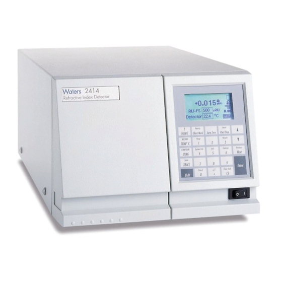
Waters designed the 2414 RI detector for high-performance liquid chromatography (HPLC) applications. It provides sensitivity, stability, and reproducibility for the analysis of components with limited or no UV absorption. The 2414 RI detector is not intended for use in diagnostic applications. -
Page 8: Ec Authorized Representative
Class B products are suitable for use in both commercial and residential locations and can be directly connected to a low voltage, power-supply network. EC authorized representative Waters Corporation Stamford Avenue Altrincham Road Wilmslow SK9 4AX UK Telephone:... -
Page 9: Table Of Contents
Customer comments ................... iii Contacting Waters ..................iv Safety considerations .................. iv Safety hazard symbol notice.............. iv Considerations specific to the 2414 Refractive Index Detector ....iv FCC radiation emissions notice............v Electrical power safety notice............. v Equipment misuse notice ..............v Safety advisories ................ - Page 10 Supported IEEE-488 and Ethernet configurations ......... 44 Ethernet signal cable connections ............... 44 3.2.1 Connecting to a Waters data control system via the Ethernet port ..45 IEEE-488 signal cable connections .............. 45 3.3.1 Connecting to a Waters data control system via the IEEE-488 bus interface..
- Page 11 Connecting to an external column heater ............. 55 4 Preparing Solvents ..............57 Common solvent problems ................. 57 Selecting a solvent ..................57 4.2.1 Solvent quality ................58 4.2.2 Preparation checklist ................ 58 4.2.3 Water .................... 58 4.2.4 Buffers................... 58 4.2.5 Tetrahydrofuran (THF)..............
- Page 12 5.5.5 Setting pulse periods ............... 86 5.5.6 Setting display contrast ..............87 5.5.7 Displaying system information............87 Optimizing performance ................87 5.6.1 Attenuation and sensitivity guidelines..........87 5.6.2 Operating the trace and scale functions ..........89 Powering-off .................... 91 5.7.1 Removing buffered mobile phase ............
- Page 13 Notices ....................117 Bottles Prohibited symbol ................ 118 Required protection ................118 Warnings that apply to all Waters instruments and devices ......118 Warnings that address the replacing of fuses ..........121 Electrical and handling symbols ..............123 A.7.1 Electrical symbols................123 A.7.2...
- Page 14 June 11, 2015, 715004754 Rev. A Page xiv...
-
Page 15: 2414 Ri Detector Optics Principles
2414 RI Detector Optics Principles ® This chapter summarizes the Waters 2414 Refractive Index Detector features and describes the theory and principles of operation. 1.1 Use of refractive index detectors RI detectors are typically used to analyze carbohydrates and lipids and in polymer analyses by gel-permeation or size-exclusion chromatography. - Page 16 The refractive index of a medium has a specific value that changes with the wavelength of the incident light beam. The 2414 RI detector uses monochromatic light at a fixed wavelength, so the effect of different wavelengths of light on RI is not discussed in this guide.
- Page 17 Figure 1–1: Effect of density on RI Weight percent sucrose in water Density (g/mL) Weight percent methanol in water Density (g/mL) 1.2.1.2 Measure refraction The extent to which a beam of light is refracted when it enters a medium depends on these properties: •...
- Page 18 The following figure illustrates the relationship between angle of incidence, angle of refraction, and refractive index. Figure 1–2: Refraction of light Incoming light beam Perpendicular to surface Angle of incidence θ Medium 1, RI = n Medium 2, RI = n Angle of refraction Refracted light beam θ...
-
Page 19: Differential Refractometry
1.2.2 Differential refractometry The 2414 RI detector can measure extremely small changes in refractive index to detect the presence of sample. The small difference in RI between a reference solution and a sample solution is referred to as Δn. Δn is expressed in refractive index units (RIU). - Page 20 The following figure illustrates the external angle of deflection (φ) and its dependence on the difference in RIs between the reference and sample sides of the flow cell. Figure 1–4: How refraction changes the external angle of deflection θ φ Reference side of flow cell n + Δn...
-
Page 21: Common Ri Detection Problems
The shift in the amount of the light beam striking each element of the dual-element photodiode results in a change in the output voltage from the 2414 RI detector. The integrator registers the changes in output voltage as peaks in your chromatogram. -
Page 22: Detector Description
Chapter 4 for more information. 1.3 Detector description The detector is designed for high-performance liquid chromatography applications. It can operate as a standalone unit with an integrator or with a Waters system controller or Waters data system. Refer to Appendix B... -
Page 23: Operation Modes
• Ethernet support – Allows the 2414 RI detector to operate as a component of an ® HPLC system controlled by a chromatography data software, such as Empower ®... - Page 24 Sensitivity – Used in the scaling of the refractive index data in millivolts and affecting the front panel display, analog outputs, and remote interface data. Sensitivity is used only to generate Waters 2410/410 RI Detector-compatible data for older data systems and controllers.
-
Page 25: Flow Path
– Auto-Zero, on keypad/panel active 1.3.4 Flow path When the 2414 RI detector is acquiring data, its normal configuration for flow allows mobile phase to pass through the sample flow cell and then to waste or to the recycle valve. - Page 26 “purge out” port. A programmatically controlled solenoid valve determines the fluid path. When you purge the 2414 RI detector, solvent takes this path: Enters through inlet tubing port. Passes through the sample in tube of the countercurrent heat exchanger.
- Page 27 Figure 1–7: Flow path during purge Flow cell End Cap HE Reference Sample Cross section Counter current HE Tee connection Fluid path for Relief Solenoid purge mode valve valve (opened) (closed) Purge out Waste out Sample In You purge the flow cell before an analysis to pass fresh mobile phase into the reference side of the cell.
-
Page 28: Fluid Path Components
1.3.5 Fluid path components The fluid path of the 2414 RI detector includes these components: • Countercurrent heat exchanger • End-cap heat exchanger • Flow cell, with sample and reference sides • Solenoid valve • Pressure relief valve • Recycle valve •... - Page 29 1.3.5.3 Solenoid valve During normal operation, the solenoid valve remains open. Fluid that passes through the sample side of the flow cell flows through the solenoid valve and out through the outlet tubing (blue) to the waste reservoir. When you purge the detector, the solenoid valve closes causing fluid passing through the sample side of the flow cell to flow out through the reference side of the flow cell, through the purge outlet tubing (blue).
-
Page 30: Optics
1.3.7 Electronics The 2414 RI detector has both analog and digital components and includes a front-panel keyboard and these printed circuit (PC) boards and their interconnections: June 11, 2015, 715004754 Rev. A... - Page 31 1.3.7.1 Filter noise The 2414 RI detector uses a Hamming filter and RC filter to minimize noise. 1.3.7.1.1 Hamming filter A hamming filter is a digital, finite impulse response (FIR) filter that creates the same amount of peak height attenuation as the RC filter but enhances the filtering of high frequency noise.
- Page 32 Increasing the time-constant settings produces these effects: • Greatly decreased baseline noise. • Shortened and broadened peaks. The software includes fast or normal filtering constants at each sampling rate that are appropriate for high speed or high sensitivity applications, respectively. The following figure shows the relationship between increased filter time constant and absorbance.
-
Page 33: Temperature Control
1.3.8.1 Column heater module temperature control The 2414 RI detector controls an external column heater module through the rear panel’s column heater connection. The column heater temperature setting range is 30 to 150 °C, in increments of 1 °C. You monitor the set point temperature while the actual temperature reading is accessible via the detector’s front-panel display and the... -
Page 34: Startup Diagnostics Tests
1.3.9 Startup diagnostics tests On startup, the 2414 RI detector runs a series of automated diagnostic tests. An error message appears if any of the tests fail. These startup diagnostic tests include: •... -
Page 35: Installing The Detector
39). 2.1 Before you begin Requirement: To install the 2414 RI detector, you should know how, in general, to set up and operate laboratory instruments and computer-controlled devices and also how to handle solvents. Before installing the detector, ensure that •... -
Page 36: Unpacking
Ensure that the serial number on the detector’s rear panel nameplate or inside the front left-hand panel matches the number on its validation certificate. 2.3 Selecting a laboratory site Install the 2414 RI detector in an area that meets the requirements listed in the table below. Table 2–1:... -
Page 37: Stacking System Modules
2.4 Stacking system modules This procedure applies to system modules that are equipped with interlocking features. Warning: To avoid spinal and muscular injury, do not attempt to lift a module without assistance. Warning: To avoid crushing your fingers beneath or between modules, use extreme care when installing a module in the system stack. - Page 38 Connect the female end of the power cord to the receptacle on the rear panel of the detector. Figure 2–2: Location of power input on 2414 RI detector rear panel Power input Connect the male end of the power cord to a suitable wall outlet.
-
Page 39: Connecting Tubing And Attachments
2.6 Connecting tubing and attachments Warning: To avoid the harmful effects of personal contact with solvents, including inhalation, always wear chemical-resistant, powder-free gloves and observe good laboratory practice when you handle them. See the Material Safety Data sheets for the solvents you use. -
Page 40: Connect To Waste
Note: The 2414 RI detector, as part of an ACQUITY Arc System, can use either insulated or non-insulated sample inlet tubing. Restriction: If you are using more than one detector in your system, you must connect the 2414 RI detector as the last detector in line. -
Page 41: Connect The Valve Pack Drip Tray
3/16-inch ID Tygon tubing (from the startup kit) To connect the drip tray: If you are connecting drip tray components from the 2414 RI detector to an ACQUITY Arc system, proceed to step Cut a length of Tygon tubing sufficient to reach between the drip tray and the waste container. - Page 42 June 11, 2015, 715004754 Rev. A Page 42...
-
Page 43: Connecting Signal Cables
Empower software or MassLynx software, connected via the Ethernet network. Tip: The Ethernet port also supports the Waters PC-based Autoloader utility for installing firmware (see the Waters 2414 Refractive Index Detector release notes for details). IEEE-488 The following systems are connected via the IEEE-488 bus: •... -
Page 44: Supported Ieee-488 And Ethernet Configurations
The signal connections you need for your detector communications depend on the signal connections available on the other instruments in your Alliance HPLC system. 3.1.1 Supported IEEE-488 and Ethernet configurations You can operate a 2414 RI detector controlled by a data control system in one of these configurations: •... -
Page 45: Connecting To A Waters Data Control System Via The Ethernet Port
Ethernet communications. • As with IEEE-488 control, triggering of the inject start signal for the 2414 RI detector occurs over the Ethernet cable and so requires no external I/O cable. For additional Ethernet information, see the Waters Ethernet Instrument Getting Started Guide (P/N: 71500074403). -
Page 46: Connecting To A Waters Data Control System Via The Ieee-488 Bus Interface
3.3.1 Connecting to a Waters data control system via the IEEE-488 bus interface You can use the IEEE-488 bus to connect the detector to a Waters data system in any of the following configurations: • Empower system, via the busLAC/E™ card installed on the computer •... -
Page 47: Connecting To A Manual Injector
Alliance HPLC system, and they must be between 2 and 29. Your Alliance HPLC system can require that the IEEE-488 address for the 2414 RI detector be greater than that for other devices in the system. Consult your data system or controller operator's manual for more information on IEEE-488 communications. -
Page 48: Connecting To A Standalone Alliance E2695 Separations Module
When you use the Alliance e2695 separations module as a standalone controller (that is, not on an Ethernet or IEEE-488 bus interface or under data system control), you can make the following signal connections using the 2414 RI detector’s analog-out/event-in connectors: •... - Page 49 3.4.1.1 Generating autozero on injecting To generate the autozero function on the 2414 RI detector at the start of an injection from the Alliance e2695 separations module, make the connections shown in the table and figure below. Table 3–4:...
- Page 50 3.4.1.3 Generating chart mark and autozero signals To generate both a chart mark and an autozero signal from the Alliance e2695 separations module to the 2414 RI detector, make the connections shown in the table and figure below. Table 3–6:...
-
Page 51: Connecting To A Data Control System Using Analog Signals
3.4.2 Connecting to a data control system using analog signals To send an integrator analog output signal (–2 V to +2 V) from the 2414 RI detector to chromatography data software (through a two-channel eSAT/IN Module), make the connections shown in the table and figure, below. -
Page 52: Connecting Injection Trigger Signals
12 + Auxiliary Out 13 - Auxiliary Out Injector 3.4.3 Connecting injection trigger signals The 2414 RI detector accepts the following injection trigger signals from a manual injector: • Auto-zero signal to automatically adjust the zero offset of the detector each time the injector makes an injection •... - Page 53 Table 3–8: Autozero connections to a manual injector Detector (connector B) Manual injector connector Pin 1, Autozero + (red) Two spade-lug terminal connectors (both cables can be functionally Pin 2, Autozero – (black) identical) or similar connectors. Autozero connection to a manual injector: Detector Manual injector...
- Page 54 Figure 3–9: Chart mark connections to a manual injector Detector Manual injector connector A 1 + Inject Start 2 - Inject Start 3 Ground 4 + Purge 5 - Purge 6 + Polarity 7 - Polarity 8 Ground 9 + Chart Mark 10 - Chart Mark 11 Ground 12 + Switch...
-
Page 55: Polarity Connections
3.4.4 Polarity connections The Polarity and Polarity Enable contact closures on the rear panel of the 2414 RI detector determine the peak polarity of the output signal according to the following conditions (negative polarity results in negative, or inverted, peaks): •... - Page 56 June 11, 2015, 715004754 Rev. A Page 56...
-
Page 57: Preparing Solvents
4.1 Common solvent problems The 2414 RI detector measures changes in the refractive index (RI) of the solution flowing through the sample side of the flow cell. However, factors other than the presence of dissolved sample molecules can affect a solution’s RI. -
Page 58: Solvent Quality
4.2.1 Solvent quality Use spectral-grade or HPLC-grade solvents to better achieve these goals: • Reproducible results • Minimal instrument maintenance • Minimal optical interference A dirty or impure solvent can cause these problems: • Baseline noise and drift • Plugged columns •... -
Page 59: Solvent Degassing
Table 4–1: Refractive indices of common solvents Solvent Solvent Fluoroalkanes 1.25 Tetrahydrofuran (THF) 1.408 Hexafluoroisopropanol 1.2752 Amyl alcohol 1.410 (HFIP) Methanol 1.329 Diisobutylene 1.411 Water 1.33 n-Decane 1.412 Acetonitrile 1.344 Amyl chloride 1.413 Ethyl ether 1.353 Dioxane 1.422 n-Pentane 1.358 Ethyl bromide 1.424 Acetone... -
Page 60: Gas Solubility
4.3.1 Gas solubility The amount of gas soluble in a given volume of liquid depends on these factors: • The chemical affinity of the gas for the liquid • The temperature of the liquid • The pressure applied to the liquid Changes in the composition, temperature, or pressure of the mobile phase can lead to outgassing. -
Page 61: Solvent Degassing Considerations
To increase the length of membrane, you can connect two or more vacuum chambers in series. When you are using the Alliance separations module with the 2414 RI detector, set the in-line degasser to “on” degas mode. - Page 62 June 11, 2015, 715004754 Rev. A Page 62...
-
Page 63: Operating The Detector
Follow the instructions in this chapter while operating the detector. 5.1 Powering-on 5.1.1 Initializing Before you power-on the 2414 RI detector, verify the connector from the detector’s rear panel to the power source is properly installed. To power-on the detector, press the on/off switch located on the lower-front right-hand corner of the unit. -
Page 64: Diagnostics Failure At Startup
If one or more of the internal startup diagnostics checks fails, the detector beeps and displays an error message. 5.1.3 Using online Help The 2414 RI detector provides limited context-sensitive help. When you press “?” (Shift HOME) from a point in the program associated with an online Help screen, the Help screen appears. - Page 65 Figure 5–4: Detector keypad Reset POLARITY HOME Chart Mark Auto Zero Run/Stop METHOD Purge Recycle ° TEMP System Info Lock Previous CONFIGURE Contrast DIAG Next Scale TRACE Enter +/− Cancel Clear Field Shift The effect of pressing a primary function key is immediate; no further entry is required.
- Page 66 Table 5–1: Keypad description (continued) Description Unshifted Shifted Chart Mark – Causes a Polarity – Changes the algebraic Polarity momentary pulse to the analog sign of the output signal. Current Chart Mark output. This key has no effect if polarity is indicated by icon. chart mark is disabled on Home screen 4.
- Page 67 Table 5–1: Keypad description (continued) Description Unshifted Shifted TRACE – Displays the RIU Scale – When the RIU trace Scale monitor trace. screen is visible, this function TRACE permits modification of the display range in the X (time) and Y (RIU) dimensions. Shift –...
-
Page 68: Navigating The User Interface
5.1.5 Navigating the user interface When operating the 2414 RI detector follow these steps to navigate through its screens and menus: Press the Enter key (or the s and t keys) to navigate among editable fields on a display. -
Page 69: Operating In Riu Mode
5.2 Operating in RIU mode RIU mode provides front-panel method programmability. RIU mode sets µRIU as the parameter displayed on the front panel and generated at the detector output, using the RIU-FS parameter to convert RIU to a voltage. Alternative: RIU mode can also be controlled using chromatography data software. - Page 70 Table 5–2: Mode, function, and message screen icons (continued) Icon or field Icon/field name Function Shift Off/ On Blank = Shift off s = Shift on Keypad Unlock / Lock Open lock = Unrestricted keypad entry Closed lock = Parameter changes not allowed Sticky Diagnostics When the home screen displays...
-
Page 71: Navigating To And From The Home Screen In Riu Mode
Table 5–2: Mode, function, and message screen icons (continued) Icon or field Icon/field name Function Message screen icons (from left): Error, Question, Information, and Warning. 5.2.2 Navigating to and from the home screen in RIU mode Pressing HOME brings you to the home screen, from most screens. From the home screen, you can access several secondary functions. - Page 72 Figure 5–6: Secondary functions of the RIU mode home screen Home 1 Home 2 Home 3 Home 4 Press Next From the home screen, or by pressing the Next key, you can access the following functions: • RIU-FS (refractive index units full scale) – The refractive index output signal is defined by the following relationship: RIU OUT = Δn* (2 Volts / RIU FS) The RIU-FS range is 500 to 1 µRIU (default is 500).
- Page 73 2-V signal by the entered value (0- to 2000-mV range). This is useful for making minor adjustments, and for nulling any offset between the 2414 RI detector and a connected external data system. • µRIU offset - Provides an offset for adjusting the detector output. The default is 0.0 µRIU and the range is ±500.0 µRIU.
-
Page 74: Setting Up A Run In Riu Mode
• Autozero delay - Invoked only on autozeros requested from an event input or remote interface, not from the front panel. The delay range is 0 to 30 seconds (default is 10 seconds), and the front panel counts down the delay in seconds. •... - Page 75 Next. The 2414 RI detector allows programming of the timed events shown in the following table.
- Page 76 METHOD to return to the method choice list to store the method. 11. Press Reset to reset the run clock to 0. If the 2414 RI detector is configured with another external device, the inject start event programmed from that device starts the method. Note:...
- Page 77 Table 5–5: Threshold event “To” parameters Below threshold Number Switch switch state Pulse Rect Wave (Rectangular Wave) Toggle Toggle To define the pulse period of the frequency of a wave, see “Accessing the configuration screens” on page To program a threshold event: On the keypad, press the METHOD (Shift Temp×C) key.
- Page 78 To store a method: Press METHOD (Shift Temp ×C) to return to the Method choice list. From the Method choice list, press 4, Store method *. A method number field appears. Note: No warning message appears if the method number you select is being used by a previously stored method.
- Page 79 5.2.4.6 Resetting a method Resetting a stored method is a two-step process. First, you reset the current conditions to the defaults; then you save the defaults in one of the storage locations. To clear one or more methods: Note: Before you clear the method, to prevent loss of the current conditions, store them in one of the available storage slots.
-
Page 80: Operating In 410 Mode
5.3 Operating in 410 mode Unlike RIU mode, you cannot program or use methods stored in the 2414 RI detector in 410 mode. The 410 mode emulates the Waters 410/2410 by displaying the % Full Scale value used by the Waters 410 and 2410 Detectors and driving the Detector Out signal on the 2414 RI detector output. -
Page 81: Navigating To And From The Home Screen In 410 Mode
5.3.1.1 Refractive index, function, and message icons in 410 mode ° The HOME, TEMP C, and CONFIGURE screens in the detector program display the icons or fields described in the table below. For a list of ranges and defaults for the function icons and fields in 410 mode, see the table on page Table 5–6:... - Page 82 Press Next From the home screen, you can access the following functions, either from the home screen or by pressing the Next key: • Sensitivity– The Waters 410-compatible Integrator Output signal is defined by the following relationship: Δ × ×...
-
Page 83: Setting Up A Run In 410 Mode
Sensitivity is a parameter used to generate the Waters 410-compatible Integrator Output signal. The user interface provides a means for setting Sensitivity as well as displaying it. When you select this output type, the front panel displays % Full Scale as the measured parameter. -
Page 84: Operating In 410 (Remote) Mode
5.4 Operating in 410 (remote) mode The 2414 RI detector can be configured to operate in 410 (remote) mode when it is under the active control of chromatography data software or system controller, such as when it is connected to any of these systems: •... -
Page 85: Setting The Ieee Address
Figure 5–15: Configuration screens Configuration screen 1 Configuration screen 2 Configuration screen 3 5.5.2 Setting the IEEE address IEEE address – Enter the detector’s IEEE-488 bus address, from 2 through 29. If you press the CE key, the detector is removed from IEEE control. The default IEEE address is 14. -
Page 86: Setting Pulse Periods
• Autozero – Configure the Autozero input to autozero the refractive index output. You determine the response of the channel using the Enable Autozero function explained in the table on page 75 and shown in the figure on page – High –... -
Page 87: Setting Display Contrast
Figure 5–16: Set the pulse period or signal width using the switch n seconds Single pulse n seconds Rectangular wave 5.5.6 Setting display contrast Use the Contrast function to adjust the contrast of the detector display screen. When you press the Contrast key (Shift 6), the Display Contrast screen appears. Figure 5–17: Display contrast screen Use the s and t keys to adjust the contrast of the display. - Page 88 5.6.1.1 Temperature These screens control the internal detector oven and, if configured, Waters column heater module. These screens are the same for RIU and 410 modes. Figure 5–20: Temperature screen 1 Figure 5–21: Temperature screen 2 June 11, 2015, 715004754 Rev. A...
-
Page 89: Operating The Trace And Scale Functions
The temperature of the column heater connected to the column heater module port on the rear panel can be set in the range ambient +5 to 150 °C. The 2414 RI detector, which has access to the temperature sensor of the column heater module, will then try to achieve and maintain the setpoint temperature, sending control signals to the external hardware. - Page 90 To display the Scale parameters after you press the Scale key: Press Next to display T2 (starting time). The default is 0. Press Next again to display RIU1 (starting or low refractive index change). The default is auto. Press Next again to display RIU2 (ending or high refractive index change). The default is auto.
-
Page 91: Powering-Off
5.7.1 Removing buffered mobile phase To remove mobile phase from the fluid path of the 2414 RI detector: Replace the buffered mobile phase with 100% HPLC-quality water and flush the system for 10 minutes at 2 mL/min. - Page 92 June 11, 2015, 715004754 Rev. A Page 92...
-
Page 93: Maintenance Procedures
Maintenance Procedures Keep to a maintenance schedule and perform maintenance as described in this chapter. Detector maintenance involves cleaning the fluid path and replacing fuses. Warning: To avoid electrical shock, • do not open the detector’s cover. The detector’s components are not user-serviceable. - Page 94 Required tools and materials • A wrench suitable for removing and replacing the column • A solvent miscible in both the mobile phase and water (methanol is commonly used) • HPLC-grade water • A strong cleaning solvent suitable for your system (6N nitric acid is commonly used) •...
-
Page 95: Replacing Fuses
6.3 Replacing fuses Required tools and materials • Flat-blade screwdriver • Replacement fuse: F 3.15 A, 250 V 6.3.1 Identifying a faulty fuse Suspect a faulty fuse if you encounter any of these problems: • The detector fails to power-on. •... - Page 96 Figure 6–2: Sides of spring-loaded fuse holder Sides of fuse holder With minimum pressure, withdraw the spring-loaded fuse holder. Figure 6–3: Removing fuse holder Power-entry module Fuse (2) Fuse holder Remove and discard the old fuse. Ensure that the new fuse is properly rated for your requirement. Warning: To avoid fire, replace the fuse only with another of the same type and rating.
-
Page 97: Error Messages, Diagnostic Functions, And Troubleshooting
Error Messages, Diagnostic Functions, and Troubleshooting Consult this chapter when diagnosing problems with your 2414 RI detector. Because the detector measures bulk properties of the system, the source of an apparent detector problem can lie with the chromatography itself or the other instruments in your system. -
Page 98: Operational Error Messages
7.2 Performing diagnostic functions The detector runs both user-selectable and service diagnostic tests. You access the user diagnostic tests by pressing the DIAG key. Only qualified Waters service personnel can access service diagnostics. To exit any diagnostic test when it has ended, press DIAG, to return to the diagnostics choice list, or HOME, to return to the Home screen. - Page 99 • You can disable a specific sticky diagnostic test by restoring its default settings. • You can disable all active sticky diagnostic tests by pressing DIAG 1, Reset diagnostics. If no sticky diagnostic tests are active, the wrench icon does not appear in the home screen.
-
Page 100: Using The Optimize Led Diagnostic Function
4. Valve 5. Previous choices Service Diagnostics Diagnostics used by Waters service personnel. 7.2.2 Using the Optimize LED diagnostic function To use the Optimize LED diagnostic function, press DIAG 2. This diagnostic function displays the type of LED used (and automatically sets the energy level of the internal LED. -
Page 101: Display And Keypad Diagnostic Tests
When you press 2, the display fills from top to bottom and from right to left, and then the Display & keypad choice list appears.If the display does not completely fill horizontally or vertically, contact your Waters service representative. From the Display & keypad choice list, press 3 to return to the diagnostics choice list. -
Page 102: Using The Other Diagnostic Functions
When the keypad is operating properly, each key location is filled in and then cleared with another press of the key. If any key does not respond when pressed, contact your Waters service representative. Requirement: Press Enter twice to exit the keypad diagnostic. - Page 103 lower value). The oven’s actual temperature and its set point are displayed. You can edit the set point in this screen. The presence or absence of an external column heater module is also indicated. 7.2.5.3 Simulate peak From the Other diagnostics choice list, press 3, Simulate peak to generate test peaks on the chart, trace, or other output.
-
Page 104: Troubleshooting
Keep in mind that the source of apparent detector problems can be within the chromatography or your other instruments as well as the 2414 RI detector. Most detector problems are relatively easy to correct. If you are unable to correct a problem or a failed condition, contact Waters Technical Service. -
Page 105: Hardware Troubleshooting
Broken electrical Inspect electrical connections. to illuminate connection Fuse blown Inspect and, if necessary, replace fuse(s). Bad LCD or control board Contact Waters Technical Service. front panel displays odd Faulty EPROMs Contact Waters Technical characters Service. Bad LCD control board... - Page 106 If your system is exhibiting symptoms not addressed in one of the following tables, refer to “Troubleshooting” on page 104. If you need further help, contact Waters Technical Service. 7.3.2.1 Abnormal baseline Drift, noise, and cycling are common symptoms of an abnormal baseline.
- Page 107 Dirty flow cell Clean flow cell (see “Decontaminating the fluid path” on page 93). Baseline drift, descending Leaky flow cell Call Waters Technical Service. Flow cell can contain an air Properly purge the bubble system. June 11, 2015, 715004754 Rev. A...
- Page 108 Table 7–3: Abnormal baseline troubleshooting (continued) Symptom Possible cause Corrective action Short-term noise cycling Pump pulsing Add pulse dampener, and (30 sec to 60 sec) stop the flow, to confirm the correction. Inadequate solvent Connect high-flow pulse blending in pump dampener.
- Page 109 “Decontaminating the fluid path” on page 93). Baseline noise, random Analog output cable not Properly connect cable. (Continued) properly connected between 2414 and data system or recorder System improperly Plug into different outlet grounded on different electrical circuit. Use power conditioner.
- Page 110 Use the following table to troubleshoot problems with retention times. Table 7–4: Troubleshooting problems with retention times Symptom Possible cause Corrective action Erratic retention times Air bubble in pump head Degas all solvents, prime pump (see “Solvent degassing methods” on page 60).
-
Page 111: Poor Peak Resolution
Table 7–4: Troubleshooting problems with retention times (continued) Symptom Possible cause Corrective action Reproducibility errors Solvent not properly Degas solvent (see degassed “Solvent degassing methods” on page 60). Incorrect chemistry or Correct, as necessary. integration Column not equilibrated Equilibrate column. Injector problem Troubleshoot injector. -
Page 112: Incorrect Qualitative Or Quantitative Results
Symptom Possible cause Corrective action Straight baseline, no No pump flow Set pump flow rate. peaks LED not on Call Waters Technical Service. Detector not zeroed Autozero detector baseline. Improper connection Inspect cabling between between detector and unit and recorder. - Page 113 Refer to the following table to troubleshoot problems with qualitation or quantitation. Table 7–6: Incorrect results troubleshooting Symptom Possible cause Corrective action Decreased peak height Leak in injector Troubleshoot injector. Degraded, contaminated, Use fresh sample. or improperly prepared sample Column contaminated Clean or replace column.
- Page 114 June 11, 2015, 715004754 Rev. A Page 114...
-
Page 115: A Safety Advisories
The following symbols warn of risks that can arise when you operate or maintain a Waters instrument or device or component of an instrument or device. When one of these symbols appear in a manual’s narrative sections or procedures, an accompanying statement identifies the applicable risk and explains how to avoid it. -
Page 116: Specific Warnings
A.1.1.1 Burst warning This warning applies to Waters instruments and devices fitted with nonmetallic tubing. Warning: To avoid injury from bursting, nonmetallic tubing, heed these precautions when working in the vicinity of such tubing when it is pressurized: •... -
Page 117: Notices
A.1.1.2 Biohazard warning The following warning applies to Waters instruments and devices that can process material containing biohazards, which are substances that contain biological agents capable of producing harmful effects in humans. Warning: To avoid infection with potentially infectious, human-sourced products, inactivated microorganisms, and other biological materials, assume that all biological fluids that you handle are infectious. -
Page 118: Bottles Prohibited Symbol
Use eye protection when refilling or replacing solvent bottles. Requirement: Wear clean, chemical-resistant, powder-free gloves when handling samples. A.5 Warnings that apply to all Waters instruments and devices When operating this device, follow standard quality-control procedures and the equipment guidelines in this section. - Page 119 Atencion: cualquier cambio o modificación efectuado en esta unidad que no haya sido expresamente aprobado por la parte responsable del cumplimiento puede anular la autorización del usuario para utilizar el equipo. 注意:未經有關法規認證部門允許對本設備進行的改變或修改,可能會使使用者喪失操作該設 備的權利。 注意:未经有关法规认证部门明确允许对本设备进行的改变或改装,可能会使使用者丧失操 作该设备的合法性。 주의: 규정 준수를 책임지는 당사자의 명백한 승인 없이 이 장치를 개조 또는 변경할 경우, 이...
- Page 120 Attenzione: fare attenzione quando si utilizzano tubi in materiale polimerico sotto pressione: • Indossare sempre occhiali da lavoro protettivi nei pressi di tubi di polimero pressurizzati. • Spegnere tutte le fiamme vive nell'ambiente circostante. • Non utilizzare tubi eccessivamente logorati o piegati. •...
-
Page 121: Warnings That Address The Replacing Of Fuses
警告:圧⼒の か か っ た ポ リ マ ー チ ュ ー ブ を 扱 う と き は、 注意 し て く だ さ い。 • 加圧 さ れ た ポ リ マ ー チ ュ ー ブ の付近で は、 必ず保護 メ ガ ネ を 着用 し て く だ さ い。 •... - Page 122 Finding fuse types and ratings when that information appears on the instrument or device Warning: To protect against fire, replace fuses with those of the type and rating printed on panels adjacent to instrument fuse covers. Attention: pour éviter tout risque d'incendie, remplacez toujours les fusibles par d'autres du type et de la puissance indiqués sur le panneau à...
-
Page 123: Electrical And Handling Symbols
Attenzione: per garantire protezione contro gli incendi, sostituire i fusibili con altri dello stesso tipo aventi le caratteristiche indicate nel paragrafo "Sostituzione dei fusibili" del capitolo "Procedure di manutenzione". Advertencia: Para evitar incendios, sustituir los fusibles por aquellos del tipo y características indicados en la sección "Sustituir fusibles". -
Page 124: Handling Symbols
Symbol Description Functional ground Input Output A.7.2 Handling symbols The following handling symbols and their associated statements can appear on labels affixed to the packaging in which instruments, devices, and component parts are shipped. Symbol Description Keep upright! Keep dry! Fragile! Use no hooks! Upper limit of temperature... - Page 125 Symbol Description Lower limit of temperature Temperature limitation June 11, 2015, 715004754 Rev. A Page 125...
- Page 126 June 11, 2015, 715004754 Rev. A Page 126...
-
Page 127: B Specifications
Note: All performance specifications are measured following a warm-up period of two hours and with ΔT < +2 °C/hr. B.1 Physical specifications The following table lists the physical specifications for the 2414 RI detector. Table B–1: Physical specifications Attribute Specification Width 34.3 cm (13.5 inches) -
Page 128: Electrical Specifications
B.3 Electrical specifications The following table lists the electrical specifications for the 2414 RI detector. Table B–3: Electrical specifications Attribute Specification Class I Protection class Overvoltage category Pollution degree Normal (IPXO) Moisture protection Grounded ac Line voltages, nominal Power requirements... -
Page 129: Performance Specifications
One external column heater, steel: Ambient to 150 °C (302 °F), ±1.0 °C, settable 1 °C increments. 1. ASTM E1303-95 B.5 Optical component specifications The following table lists the optical component specifications for the 2414 RI detector. Table B–5: Optical component specifications Attribute... - Page 130 June 11, 2015, 715004754 Rev. A Page 130...
Need help?
Do you have a question about the 2414 and is the answer not in the manual?
Questions and answers