
Related Manuals for Waters 432


Summary of Contents for Waters 432
- Page 1 Waters 432 Conductivity Detector Operator’s Guide 34 Maple Street Milford, MA 01757 71500043202, Revision A...
- Page 2 This document is believed to be complete and accurate at the time of publication. In no event shall Waters Corporation be liable for incidental or consequential damages in connection with or arising from the use of this document.
- Page 3 Note: When you use the instrument, follow generally accepted procedures for quality control and methods development. If you observe a change in the retention of a particular compound, in the resolution between two compounds, or in peak shape, immediately determine the reason for the changes.
- Page 4 Caution: Use caution when working with any polymer tubing under pressure: • Always wear eye protection when near pressurized polymer tubing. • Extinguish all nearby flames. • Do not use Tefzel tubing that has been severely stressed or kinked. • Do not use Tefzel tubing with tetrahydrofuran (THF) or concentrated nitric or sulfuric acids.
- Page 5 Precauzione: prestare attenzione durante le operazioni con i tubi di polimero sotto pressione: • Indossare sempre occhiali da lavoro protettivi nei pressi di tubi di polimero pressurizzati. • Estinguere ogni fonte di ignizione circostante. • Non utilizzare tubi Tefzel soggetti a sollecitazioni eccessive o incurvati. •...
- Page 7 Caution: The user shall be made aware that if the equipment is used in a manner not specified by the manufacturer, the protection provided by the equipment may be impaired. Attention : L’utilisateur doit être informé que si le matériel est utilisé d’une façon non spécifiée par le fabricant, la protection assurée par le matériel risque d’être défectueuses.
- Page 8 Caution: To protect against fire hazard, replace fuses with those of the same type and rating. Attention : Remplacez toujours les fusibles par d’autres du même type et de la même puissance afin d’éviter tout risque d’incendie. Vorsicht: Zum Schutz gegen Feuergefahr die Sicherungen nur mit Sicherungen des gleichen Typs und Nennwertes ersetzen.
- Page 9 Caution: To avoid possible electrical shock, disconnect the power cord before servicing the instrument. Attention : Afin d’éviter toute possibilité de commotion électrique, débranchez le cordon d’alimentation de la prise avant d’effectuer la maintenance de l’instrument. Vorsicht: Zur Vermeidung von Stromschlägen sollte das Gerät vor der Wartung vom Netz getrennt werden.
- Page 10 Commonly Used Symbols Direct current Courant continu Gleichstrom Corrente continua Corriente continua Alternating current Courant alternatif Wechselstrom Corrente alternata Corriente alterna Protective conductor terminal Borne du conducteur de protection Schutzleiteranschluss Terminale di conduttore con protezione Borne del conductor de tierra...
- Page 11 Commonly Used Symbols (Continued) Frame or chassis terminal Borne du cadre ou du châssis Rahmen- oder Chassisanschluss Terminale di struttura o telaio Borne de la estructura o del chasis Caution or refer to manual Attention ou reportez-vous au guide Vorsicht, oder lesen Sie das Handbuch Prestare attenzione o fare riferimento alla guida Actúe con precaución o consulte la guía Caution, hot surface or high temperature...
- Page 12 Commonly Used Symbols (Continued) Caution, risk of electric shock (high voltage) Attention, risque de commotion électrique (haute tension) Vorsicht, Elektroschockgefahr (Hochspannung) Precauzione, rischio di scossa elettrica (alta tensione) Precaución, peligro de descarga eléctrica (alta tensión) Caution, risk of needle-stick puncture Attention, risques de perforation de la taille d’une aiguille Vorsicht, Gefahr einer Spritzenpunktierung Precauzione, rischio di puntura con ago...
- Page 13 Commonly Used Symbols (Continued) Fuse Fusible Sicherung Fusibile Fusible Electrical power on Sous tension Netzschalter ein Alimentazione elettrica attivata Alimentación eléctrica conectada Electrical power off Hors tension Netzschalter aus Alimentazione elettrica disattivata Alimentación eléctrica desconectada...
- Page 14 Intended Use ® The Waters 432 Conductivity Detector can be used for in-vitro diagnostic testing to analyze many compounds, including diagnostic indicators and therapeutically monitored compounds. When you develop methods, follow the “Protocol for the Adoption of Analytical Methods in the Clinical Chemistry Laboratory,” American Journal of Medical Technology, 44, 1, pages 30–37 (1978).
-
Page 15: Table Of Contents
Table of Contents Preface ..................23 Chapter 1 Introduction ..................26 Chapter 2 Installing the Detector ..............30 2.1 Selecting the Installation Site..........30 2.2 Unpacking and Inspection............. 31 2.3 AC Power Connection ............32 2.4 I/O Signal Connections ............35 2.4.1 I/O Signal Descriptions .......... - Page 16 Chapter 3 Operating the Detector ..............56 3.1 Controls and Indicators ............56 3.2 Startup and Shutdown ............61 3.3 Operating Recommendations ..........62 Chapter 4 Performing Ion Analysis ..............64 4.1 Fundamental Considerations ..........64 4.2 Configuring the System............68 4.3 Eluents for Ion Analysis............
- Page 17 Appendix A Specifications ................... 87 Appendix B Spare Parts..................90 Appendix C Ion Chromatography Methods ............91 C.1 General-Purpose Anion Analysis Using Conductivity and UV Detection ..............91 C.1.1 Preparing Eluent ............93 C.1.2 Preparing Standards ..........93 C.1.3 Preparing a Sample ..........93 C.1.4 Empower Data Processing Method......
- Page 18 C.2 Alkali and Alkaline Earth Cations, Ammonium, and Amines................ 103 C.2.1 Preparing Eluent ............ 104 C.2.2 Preparing Standards ..........104 C.2.3 Preparing a Sample ..........105 C.2.4 Empower Data Processing Method......105 C.2.5 Method Detection Limits.......... 106 C.2.6 Examples of Use............. 107 C.2.7 Preparing Stock Reagent ........
- Page 19 IEEE-488 Address Switch.............. 38 Bus SAT/IN Module (Front Panel) ..........40 Bus SAT/IN to Bus LAC/E Connections ......... 42 Bus SAT/IN to 432 Detector Connections........43 Alliance Separations Module Connections to the 432 Detector Auto-Zero on Inject............47 Alliance Separations Module Connections to the 432 Detector Chart Mark on Inject............
- Page 20 Calibration Curves for Chloride, Fluoride, and Bromide ....95 Calibration Curves for Nitrite and Nitrate ........96 Calibration Curves for Sulfate and Phosphate ......96 100-mL Injection ................97 Typical Drinking Water, No Dilution Required ......100 Direct UV Detection ..............101 100-ppb Anion Standard .............
- Page 21 List of Tables Limiting Equivalent Conductance of Ions in Water at 25 °C ..29 Power Cord Wire Identification ............. 33 Nominal Operating Voltage............34 I/O Signal Descriptions ............36 IEEE-488 DIP Switch Setting ..........38 Bus SAT/IN Cable Connections ..........44 Data Module Signal Cable Connections ........
- Page 22 Communications ................89 Spare Parts ................... 90 Required Instrumentation ............. 91 Analysis Conditions ..............92 IC Processing Method Using Peak Apex for Retention Time ..94 Method Validation ................. 95 Quantitation Precision..............97 Quantitation Accuracy..............98 Analyte Recovery................99 Required Instrumentation ............103 Analysis Conditions ..............
-
Page 23: Preface
Detector. It also includes appendixes listing specifications and spare parts and describing validation support. This guide is intended for use by personnel who need to install, operate, maintain, or troubleshoot the 432 Detector. This guide assumes an understanding of the principles of chromatography. Organization... - Page 24 Adobe Acrobat Reader lets you easily print pages, page ranges, or the entire document by selecting File > Print. For optimum print quantity, Waters recommends that you specify a ® PostScript printer driver for your printer. Ideally, use a printer that supports 600 dpi print resolution.
- Page 25 Convention Usage … Three periods indicate that more of the same type of item can optionally follow. For example, “You can store filename1, filename2, … in each folder.” A right arrow between menu options indicates you should choose > each option in sequence. For example, “Select File >...
-
Page 26: Chapter 1 Introduction
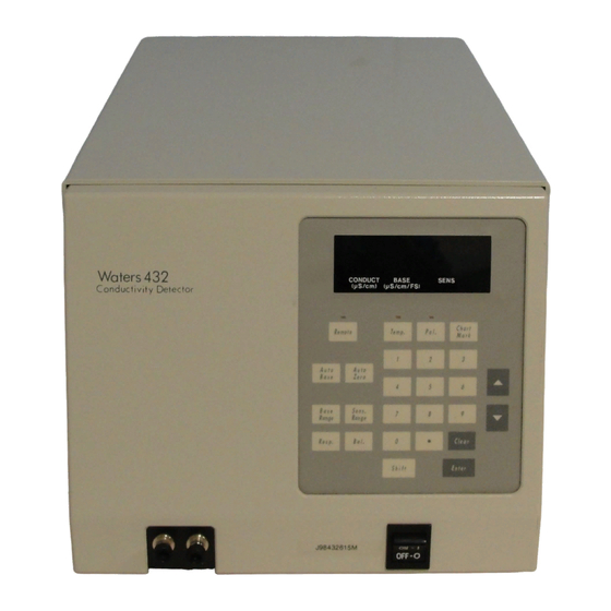
• Heat exchanger and a built-in automatic temperature control system for stable operation • Auto baseline/auto zero • External recorder/integrator and chart mark connections • Three time constant selections • “Leak-detected” alarm signal TP01268 Figure 1-1 Waters 432 Conductivity Detector... - Page 27 Appendix A, Specifications Measurement Technique The 432 Detector responds to all ions present in the flow cell, since all ions in solution conduct electricity. This allows the 432 Detector to detect a wide variety of sample ions. The 432 Detector eliminates the eluent’s contribution to conductivity with an electronic technique called baseline suppression.
-
Page 28: Flow Cell Schematic
1= Reference Electrodes 2= Detection Electrodes 3= Guard Electrode Flow Cell Block (heated) Fluid Outlet TP01271 Figure 1-2 Flow Cell Schematic Ion Detection Theory The conductance of a solution of known concentration can be calculated using the following equation: λC ---------- 3 –... -
Page 29: Limiting Equivalent Conductance Of Ions In Water At 25 °C
Table 1-1 Limiting Equivalent Conductance of Ions in Water at 25 °C λ Cations Anions — OH − 349.8 198.6 F − 38.6 55.4 Cl − 50.1 76.4 Br − 73.5 78.1 I − 77.8 76.8 − 61.9 71.5 − 73.3 64.6 −... -
Page 30: Installing The Detector
Chapter 2 Installing the Detector This chapter guides you through the following steps in preparing the 432 Detector for operation in a chromatographic system: • Selecting an installation site that satisfies the detector’s power and environmental requirements • Unpacking and inspecting the 432 Detector and accompanying items •... -
Page 31: Unpacking And Inspection
• Packing list • Declaration of conformity Note: If you purchased the 432 Detector as part of an ion/liquid chromatograph system, a Waters representative will perform the installation and startup. To unpack the 432 Detector: 1. Locate the packing list. -
Page 32: Ac Power Connection
2.3 AC Power Connection Caution: To avoid a potential fire hazard and damage to the 432 Detector, make sure that the voltage selector in the power connector is set correctly to match the available AC power source, and that the correct fuses are installed before you apply AC power. -
Page 33: Rear Panel
Neutral Green Green/Yellow Ground (Earth) The 432 Detector can be adapted to operate within two voltage ranges at 50 or 60 Hz. Table 2-2 describes these voltage ranges and the fuse value that is appropriate to each. Installing the Detector... -
Page 34: Changing The Voltage Setting
Table 2-2 Nominal Operating Voltage Nominal Voltage (VAC) Fuse 100/120 T 2A 220/240 T 1A Required Material You need a flat-blade screwdriver to perform this procedure. Procedure Caution: To avoid the possibility of electrical shock, turn off the front panel power switch and unplug the power cord. -
Page 35: I/O Signal Connections
2.4 I/O Signal Connections The 432 Detector is usually installed as an integral part of a data collection system. You can control the 432 Detector either locally from the keypad on the front panel or remotely from a PowerLine™ controller, such as the Waters 600S. -
Page 36: I/O Terminal Strip
– – – – Leak LEAK MARKER Marker In – – MARKER Marker Out Auto Zero AUTO ZERO – – Figure 2-3 I/O Terminal Strip Table 2-3 I/O Signal Descriptions Terminal Pairs Function Rec (+ and –) Recorder output – A 10-mV full-scale analog output signal appears on these terminals. -
Page 37: Powerline Controller Connections
3. Remove the DIP switch cover (Figure 2-1) using a 2.5-mm Allen wrench. 4. Refer to Table 2-4 to set the DIP switches on the rear panel of the 432 Detector (Figure 2-4) to a unique IEEE-488 address between 2 and 29. -
Page 38: Ieee-488 Address Switch
(Address 8 Shown) Figure 2-4 IEEE-488 Address Switch The IEEE-488 address DIP switch employs positive logic to determine the address of the 432 Detector from the switch settings. Table 2-4 shows the settings for valid addresses. Table 2-4 IEEE-488 DIP Switch Setting... -
Page 39: Empower And Millennium Connections
Address PowerLine Operation Under PowerLine control, the 432 Detector is recognized as a 431 Detector and it retains the functionality of the 431 Detector with the following differences: • The Balance field on the detector setup page of the PowerLine controller affects the Integrator Balance and the Integrator Output only. -
Page 40: Bus Sat/In Module (Front Panel)
LAC/E • Connect the 432 Detector to the Bus SAT/IN module (Channel 1 or 2). • Remove the IEEE-488 cable from the rear panel of the 432 Detector, if it is connected. The 432 Detector is in local mode when it is connected to an Empower and Millennium computer. - Page 41 Note: To prevent damage to the unit, always disconnect the power cord at either the wall outlet or the power supply before you attach or remove the power connection to the Bus SAT/IN module. The Bus SAT/IN module does not have a power switch. Connecting the Bus SAT/IN Module to the Bus LAC/E Card The Bus SAT/IN module connects to the Bus LAC/E through an I/O distribution box, as shown in...
-
Page 42: Bus Sat/In To Bus Lac/E Connections
I/O Distribution Por t (9-pin) of Bus LAC/E Card I/O Distribution Cable Modified Modular Jack Connections I/O Distribution Box Serial Cable SAT/IN Module Rear Panel Connect SAT/IN to Port 1 on the I/O Distribution Box DATA AC to DC Converter Figure 2-6 Bus SAT/IN to Bus LAC/E Connections I/O Signal Connections... -
Page 43: Bus Sat/In To 432 Detector Connections
To connect the 432 Detector to the Bus SAT/IN module: 1. Connect the white wire of the analog cable (included with the Bus SAT/IN module) to the Int + terminal on the rear panel of the 432 Detector. Connect the black wire to the Int – terminal. -
Page 44: Data Module Connections
Waters 717plus (or equivalent) Autosampler. 4. Remove the IEEE-488 cable from the rear panel of the 432 Detector, if it is connected. The connections from the 432 Detector to the Bus SAT/IN are summarized in Table 2-5. -
Page 45: Chart Recorder Connections
Use the signal to start a Waters 746 Data Module by connecting a signal cable to the module’s data cable (Table 2-7). Table 2-7 Data Module Chart Mark Cable Connections 432 Detector I/O Wire Connector Cable Terminal Either wire Marker Out... -
Page 46: Auto Zero Input Connections
The voltage at the Recorder and Integrator outputs is set to the user-selected balance offset level when a contact closure occurs between the Auto Zero terminals. This section describes how to connect the 432 Detector to the following devices (so that an auto zero occurs at the injection point): •... -
Page 47: Alliance Separations Module Connections To The 432 Detector Auto-Zero On Inject
Pin 2 Inject Start Auto-Zero (–) Before you can generate an Auto-Zero from an Alliance Separations Module, you must configure the Auto-Zero signal at the 432 Detector front panel. The default Auto-Zero signal is Low. Waters Alliance Waters 432 Detector... -
Page 48: Making Fluidic Connections
Figure 2-9 Alliance Separations Module Connections to the 432 Detector Chart Mark on Inject 2.5 Making Fluidic Connections Fluid lines to a column and waste container connect to the front of the 432 Detector, as shown in Figure 2-10. To make these connections: •... -
Page 49: Fluid Connections
Conductivity detection is sensitive to flow rate fluctuations. If you use a STOP non-Waters pump or a Waters pump without the SILK microflow compensation algorithm, you must install the pulse dampener kit supplied in the Startup Kit for optimum performance. Refer to the installation procedure in this section. -
Page 50: Cutting Polymeric Tubing
Cutting Polymeric Tubing Waters chromatography systems are supplied with a tubing cutter (similar to the one in Figure 2-11) to facilitate cutting polymeric tubing. This section presents the recommended procedure for using the tubing cutter. Note: To avoid bandspreading caused by angled cuts, always use a tubing cutter. Angled cuts leave unswept dead volumes at the connection junction due to the poor fit of the tubing against the connector or port. -
Page 51: Ferrule And Compression Screw Assembly
(detector inlet). 2. Push the free end of the tubing as far as it will go into the IN fitting on the 432 Detector. While you hold it there, use a 5/16-inch open-end wrench to tighten the compression screw 3/4-turn past finger-tight. - Page 52 Installing the Pulse Dampener To achieve the best performance from the 432 Detector in a chromatographic system with a non-Waters pump, Breeze™ software, or Waters HPLC 515 Pump, you must install the pulse dampener kit supplied in the Startup Kit. The pulse dampener is not required if you are using a Waters 2695 Separations Module.
-
Page 53: Passivating The System
Use this procedure for Waters hardware only. For other equipment, check with the manufacturer before you continue with this procedure. Attention: If you are installing the 432 Detector into an existing Waters system, replace STOP the pump seals before you passivate. Use the new pump seals supplied in the Startup Kit and refer to the replacement procedure in the pump manual. -
Page 54: Verifying The Detector
5 mL of water into the top hole in the baseplate of the pump heads. Place a tissue under the baseplates to absorb the water. 9. Set the pump flow rate to 0.0 mL/min. It is not necessary to turn off the 432 Detector unless it will be idle for an extended period (14 days). - Page 55 Waters suggests one of its Technical Service Representatives perform this procedure. 1. Turn on the 432 Detector and set the temperature control to 35 °C. Allow 2 to 3 hours for the temperature in the flow cell to equilibrate. 2. Set the base range to 200 µS.
-
Page 56: Operating The Detector
• A description of front panel controls and displays • Procedures for starting up, shutting down, and long-term storage • Recommended operating practices 3.1 Controls and Indicators Figure 3-1 illustrates the controls and indicators on the front panel of the 432 Detector. Waters 432 Conductivity Detector 0.0005 CONDUCT... - Page 57 The power switch (located in the lower-right corner of the front panel) controls power to the 432 Detector. Upon startup, an initialization routine verifies the data in ROM memory, tests RAM memory function, and checks for any internal leakage or an eluent conductivity over-range condition.
-
Page 58: Key Descriptions
When positive polarity is selected, the light Pol. above the key is illuminated. Base Range key: Sets the base sensitivity range of the 432 Detector to the appropriate value for the eluent being used. The base sensitivity is Base Range set to one of ten steps, from 10 µS (maximum gain) to 10,000 µS, using... - Page 59 Table 3-1 Key Descriptions (Continued) Function Response key: Sets the response time constant of the 432 Detector to optimize signal-to-noise ratio. Use the Up and Down keys or the numeric Resp. keypad to choose Setting 1 (Fast, 0.25 sec) for very narrow peaks, Setting 2 (Standard, 0.5 sec), or Setting 3 (Slow, 1.0 sec) to detect wider...
-
Page 60: Setting The Beep Function
Function Up key: Increments the current parameter setting. Down key: Decrements the current parameter setting. Beep Function You can set the 432 Detector to beep when a key is pressed and/or an error condition is detected. Use the Clear key to stop an error alarm. For a continuing error condition, the error message remains after the beep is cleared. -
Page 61: Startup And Shutdown
To eliminate the need to allow time for the flow cell temperature to equilibrate, leave the 432 Detector turned on at the end of the workday or workweek. Set the temperature control to the operating temperature and the pump flow rate to 0.01 to 0.1 mL/min (depending on the pump). -
Page 62: Operating Recommendations
Long-Term Storage If the 432 Detector is to be removed from a system for storage or if the system itself is to be stored for a long time, flush the detector/system with 100% water, then 100% HPLC-grade methanol. Leave the methanol in the system after shutdown. If you are removing the 432 Detector from the system, seal the inlet and outlet bulkheads with dead-end fittings or a loop of tubing. - Page 63 Polarity Signal polarity depends on eluent conductivity. If necessary, press the Polarity key to obtain peaks rather than dips. Eluent Handling Replace your eluent reservoir filter regularly. When you analyze cations, use an all-plastic eluent reservoir filter. Filter and degas eluents to prolong column life, reduce pressure fluctuations, and decrease baseline noise.
-
Page 64: Performing Ion Analysis
Performing Ion Analysis This chapter provides essential information about ion analysis techniques. Two representative columns serve as typical examples: the Waters IC-Pak A for anions and the IC Pak C M/D for cations. The following topics are discussed: • Fundamental considerations •... - Page 65 “Selection and Cleaning of Plastic Containers for Storage of Trace Element Samples,” JR Moody and RM Lindstrom, Analytical Chemistry, v. 49, Dec 1977, pp. 2264-67, or contact the Waters Technical Services Department. Cleaning Syringes To avoid contamination, always rinse a syringe two to three times with ASTM Type I reagent water before you draw standards or samples for injection.
- Page 66 ® carbonate absorption, connect a soda lime (Ascarite ) tube (Figure 4-1) to the eluent bottle as follows: 1. Insert a 3/4-inch (2-cm) piece of glass wool in one end of a polyethylene tube with end fittings. Attach the end fitting. Caution: To avoid chemical burns, wear gloves, lab coat, and eye glasses when you are handling soda lime.
-
Page 67: Soda Lime Tube
End Fittings Glass Wool Soda Lime Polypropylene Tube Pump Inlet Line Reagent Bottle Figure 4-1 Soda Lime Tube Sample Preparation Sample preparation is very important in ion analysis. Contact the Waters Technical Services Department, if you need assistance. Performing Ion Analysis... -
Page 68: Configuring The System
Pulse Dampener † Reservoir * Optional Required for non-Waters pumps or Waters pumps with Breeze software, such † Required for Waters pumps without SILK or non-W aters pumps TP01269 as the HPLC 515 Figure 4-2 System Configuration for Ion Analysis... -
Page 69: Eluents For Ion Analysis
Pulse Dampener If your system uses a non-Waters pump or a Waters pump with Breeze software, such as the HPLC 515, use a pulse dampener (supplied in the Startup Kit) to achieve the best performance from the 432 Detector. Install the pulse dampener between the pump and the injector, as described in “Installing... -
Page 70: Preparing Anion Eluent
Consult the manufacturer’s manual for your column (IC-Pak Column and Guard Column Care and Use Manual included with Waters columns) for additional instructions on the selection and preparation of eluents. A recommended source for more information about ion analysis in general is “Ion Chromatography: Principles and Applications,”... -
Page 71: Preparing Anion Standards
Storing Standards For accurate quantitative results, do not store standards beyond the approximate periods listed in Table 4-1. Be aware that shelf-life depends on many factors and may be significantly shorter than shown here. Table 4-1 Shelf-Life of Standards Standard Shelf-Life Carbonate, ppm 1 day... -
Page 72: Injecting Anion Standards
Table 4-2 Salts for Anion Standard Concentrates Salt (Anion) Weight (mg) – Sodium fluoride (F 221.0 – Sodium chloride (Cl 164.9 Sodium nitrite (NO – 150.0 – Potassium bromide (Br 148.9 – Sodium nitrate (NO 137.1 Potassium phosphate, 141.8 2– monobasic (HPO 2–... - Page 73 100-µL injection volume. When you use a fixed loop, overfill a minimum of three times. Injecting the Standard To inject the standard: 1. Set up the 432 Detector as follows: • Base Sensitivity = 500 µS • Integrator Sensitivity = 10 µS/V • Recorder Sensitivity = 0.01 (strip chart) •...
-
Page 74: Preparing Cation Standards
Figure 4-3 Chromatogram of a 7-Anion Standard 4.4.3 Preparing Cation Standards This section presents the procedure for preparing an 8-cation standard. If a simpler standard suffices, follow this procedure selecting only those salts that you want in the standard. For accurate quantitative results, use only properly prepared plasticware and do not store standards beyond the recommended shelf-lives listed in Table 4-1. -
Page 75: Salts For Cation Standard Concentrates
(Mol. Wt. Salt / Mol. Wt. Cation) = g Salt If you choose to use other salts, be sure to avoid any combinations that will form a precipitate. Table 4-4 Salts for Cation Standard Concentrates Salt (Cation) Weight (g) Lithium hydroxide monohydrate (Li + ) 6.0476 Sodium chloride (Na + ) 2.5421... -
Page 76: Injecting Cation Standards
Cations, Ammonium, and Amines, for the following procedure. Use this procedure to inject the standard. 1. Set up the 432 Detector as follows: • Base Sensitivity = 2000 µS • Integrator Sensitivity = 50 µS/V • Recorder Sensitivity = 0.01 (strip chart) •... -
Page 77: Chromatogram Of An 8-Cation Standard
Figure 4-4 Chromatogram of an 8-Cation Standard Performing Ion Analysis... -
Page 78: Chapter 5 Maintenance
To avoid the possibility of electric shock, power off the detector and disconnect the power cord before you service the instrument. 5.1 Routine Maintenance This section contains information designed to help you maintain the 432 Detector. Routine maintenance for the 432 Detector includes: • Replacing the fuse •... -
Page 79: Maintaining The Flow Cell
5.1.2 Maintaining the Flow Cell Maintenance for the 432 Detector consists of ensuring the flow cell is free of foreign material. Foreign material in the flow cell may cause baseline drift, cycling, or noise. Attention: To avoid damaging the column, remove it before you flush the system. - Page 80 To avoid electrical hazards, always unplug the power cord before you perform any of the following replacement procedures. 1. Unplug the 432 Detector from the power source, and completely disconnect all electrical cables and fluid connections. 2. Remove the 432 Detector cover (four Phillips-head screws, two on each side).
-
Page 81: Flow Cell Assembly
Cell block cover Pin holder Pin holder Insulation Upper plate screws Upper plate of cell block Cell mounting bracket screws Cell mounting bracket Connector Flow cell Cell block Figure 5-2 Flow Cell Assembly Maintenance... -
Page 82: Cleaning The Detector Exterior
5.2 Cleaning the Detector Exterior To clean the outside of the 432 Detector, use only a soft lint-free paper or cloth dampened with mild soap and water. 5.3 Troubleshooting This section contains troubleshooting charts to help you isolate and correct problems with the 432 Detector. - Page 83 • Power surges • Line spikes • Transient energy sources Be sure that the electrical supply used for the 432 Detector is properly grounded and free from any of these conditions. Error Messages The error messages displayed by the 432 Detector are listed below along with the recommended action for each: •...
- Page 84 4. Flush four times with 1-mL portions of HPLC-grade methanol. 5. Flush four times with 1-mL portions of ASTM Type I reagent water. 6. Reattach the tubing from the 432 Detector outlet to a waste receptacle (18-inch length of 0.009-inch ID stainless steel).
-
Page 85: Troubleshooting Guide
Excessive baseline Unstable temperature control Make sure the temperature drift control is turned on. Defective cell heater Call Waters service. Temperature changes in room Control ambient tempera- ture, locate drafts, and insulate tubing and column, if necessary. Cell temperature set lower than... - Page 86 Table 5-1 Troubleshooting Guide (Continued) Symptom Possible Cause Solution Bubbles in flow cell Remove bubbles and degas the solvent. Solvent changeover Wait until baseline stabilizes (purge autosampler a few times). Flow cell leak Check flow cell fittings and tighten. If leak continues, replace the flow cell.
-
Page 87: Appendix A Specifications
Appendix A Specifications This appendix includes information on: • Operational specifications • Mechanical specifications • Environmental specifications • Electrical specifications • Communications Table A-1 Operational Specifications Condition Specification Less than 0.05 µS/hr/°C (ambient) Drift 200 µS Base: Sensitivity: 0.005 Eluent: 1 mM KCI Less than 0.005 µS/cm Noise... -
Page 88: A-4 Electrical Specifications
Table A-2 Mechanical Specifications (Continued) Condition Specification Operating pressure 70 psi maximum Height 9.4 inches (23.8 cm) Length 21 inches (53.3 cm) Width 11.5 inches (29.2 cm) Weight 17.7 pounds (8 kg) Table A-3 Environmental Specifications Condition Specification Operating temperature range 4 to 35 °C (40 to 95 °F) Operating humidity... -
Page 89: A-5 Communications
– b. Over Voltage Category II Pertains to instruments that receive their electrical power from a local level such as an electrical wall outlet. – c. Pollution Degree 2 A measure of pollution on electrical circuits, which may produce a reduction of dielectric strength or surface resistivity. Degree 2 refers to normally only nonconductive pollution. -
Page 90: Appendix B Spare Parts
The flow cell (part number 043069) is considered a replacement part. Order the flow cell only when it is needed for replacement in the Waters 432 Detector. Fill in the information below for easy reference when you order parts or request service. -
Page 91: Ion Chromatography Methods
C.1 General-Purpose Anion Analysis Using Conductivity and UV Detection Table C-1 Required Instrumentation Instrument Part Number Alliance, 2695 Separations Module or Breeze (with column heater, seal wash, and degasser) 432 Conductivity Detector 043061 busSAT/IN Module 200415 Empower/Breeze data processing Contact Waters UV Detector (optional) -
Page 92: Common Anion Standards
Figure C-1 Common Anion Standards Table C-1 Analysis Conditions Condition Value Column IC-Pak A/HR (part number 026765) Eluent Borate/gluconate containing 12% AcCN 240 ±20 µS Back conductivity Degas Continuous Flow rate 1 mL/min. 1200 ±200 psi Backpressure Temperature 30 °C for column heater, 35 °C for detector 100 µL Injection Needle wash... -
Page 93: Preparing Eluent
C.1.1 Preparing Eluent 1. Add 20 mL of lithium borate/gluconate concentrate and 120 mL of HPLC-grade acetonitrile (AcCN) into a 1-liter volumetric flask (see Section C.1.13, Preparing Lithium Borate/Gluconate 50X Stock Concentrate, for concentrate preparation). 2. Dilute to volume with DI water. 3. -
Page 94: Empower Data Processing Method
C.1.4 Empower Data Processing Method Table C-2 IC Processing Method Using Peak Apex for Retention Time Process Values Integration Peak Width = 30.0 Minimum Area = 3000 Inhibit Intg. = 0 to 2 min. Threshold = 10 to 25 Minimum Height = 150 Calibration Averaging = None Update RT = Never... -
Page 95: Method Validation
C.1.5 Method Validation This validation design is abstracted from ASTM/EPA validation. It has been used to validate all anion analysis methods. Many of the methods using this validation design are linear above 50 ppm. Table C-3 Method Validation Individual Youden Pair Standard, in ppm 15.0 40.0 20.0... -
Page 96: Calibration Curves For Nitrite And Nitrate
= 0.9999 = 0.9992 Figure C-3 Calibration Curves for Nitrite and Nitrate = 0.9999 = 0.9992 Figure C-4 Calibration Curves for Sulfate and Phosphate Ion Chromatography Methods... -
Page 97: Quantitation Precision
C.1.7 Quantitation Precision Quantitation Precision is the percent RSD of analyte peak area at each concentration. Data is based on seven replicate injections of the validation standards. Table C-4 Quantitation Precision Analyte 0.95 1.11 3.44 5.17 0.32 12.98 7.62 0.67 1.64 0.78 1.73... -
Page 98: Quantitation Accuracy
Based on this representative chromatogram using a 100-µL injection, the estimated detection limits, as ppb, at three times signal to noise (S/N) are as follows: • Fluoride = 50 • Chloride = 25 • Nitrite = 50 • Bromide = 75 •... -
Page 99: Analyte Recovery
C.1.10 Analyte Recovery The Certified Performance Evaluation Standards were diluted 1:100 with typical drinking water. Amounts are based on a multi-point calibration. Table C-6 Analyte Recovery Analyte 25.82 0.23 8.30 Milford detected ±0.04 detected ±0.002 detected 0.02 Drinking Water n=3, as ppm 0.16 0.92 0.27... -
Page 100: Example Of Use
C.1.11 Example of Use Figure C-6 Typical Drinking Water, No Dilution Required C.1.12 Using Direct UV Detection Many anions are UV active in the range of 205 to 214 nm, such as NO , Br, and NO , and the use of direct UV detection provides a degree of detector selectivity. Figure C-7 shows the chromatogram of the anion standard that demonstrates this selectivity. -
Page 101: Direct Uv Detection
Direct UV detection is five times more responsive for nitrite and nitrate than is conductivity detection and therefore provides lower detection limits. The chromatogram in Figure C-8 of a 100-ppb anion standard demonstrates the improved sensitivity. Waters 996 Photodiode Array Detector Figure C-8 100-ppb Anion Standard Ion Chromatography Methods 101... -
Page 102: Preparing Lithium Borate/Gluconate 50X Stock Concentrate
The borate/gluconate eluent has some UV absorption. Use of eluents that are UV transparent, such as hydroxide and carbonate/bicarbonate, provide lower detection limits. C.1.13 Preparing Lithium Borate/Gluconate 50X Stock Concentrate 1. Using a 60-mL plastic syringe, add approximately 25 g of BioRad AG-50W-X12 strong cation exchange resin in the hydrogen form, or equivalent. -
Page 103: Alkali And Alkaline Earth Cations, Ammonium, And Amines
C.2 Alkali and Alkaline Earth Cations, Ammonium, and Amines Table C-1 Required Instrumentation Instrument Part Number Alliance, 2695 Separations Module or Breeze (with column heater, seal wash, and degasser) 432 Conductivity Detector 043061 busSAT/IN Module 200415 Empower/Breeze data processing Contact Waters Figure C-9 1-ppm Standard... -
Page 104: Preparing Eluent
Table C-2 Analysis Conditions Condition Value Column IC-Pak C/MD Eluent 3 mM HNO /0.1 mM EDTA 1250 ±50 µS Back conductivity Degas Continuous Flow rate 1 mL/min. Backpressure 2100 psi Temperature 30 °C for column heater, 35 °C for detector 100 µL Injection Needle wash... -
Page 105: Preparing A Sample
calibration curve is validated, a single-point calibration curve within the expected analyte concentration is appropriate for future calibrations. You can use this method for the analysis of Rb, Cs, Sr, and Ba. C.2.3 Preparing a Sample 1. Determine the expected range of analyte concentration and other anionic component in the sample matrix. -
Page 106: Method Detection Limits
Table C-3 IC Processing Method Using Peak Apex for Retention Time (Continued) Process Values Report Analyte Name Analyte Retention Time Peak Area Amounts C.2.5 Method Detection Limits Figure C-10 25-ppb Cation Standard Based on this representative chromatogram using a 100-µL injection in a 2695 Separations Module, the estimated detection limits, as ppb, at three times signal to noise (S/N) are as follows: •... -
Page 107: Examples Of Use
• Calcium = 15 You can achieve lower detection limits by using a 250-µL injection. C.2.6 Examples of Use Figure C-11 Typical Drinking Water, No Dilution Required Figure C-12 Typical Municipal Wastewater, Diluted 1:50, Overlay of Duplicate Injections Ion Chromatography Methods 107... -
Page 108: Preparing Stock Reagent
Note: Alkyl and alkanol amine analysis standards are between 1 and 5 ppm, 3 mM /0.1 mM EDTA/3% AcCN. C.2.7 Preparing Stock Reagent Because it is difficult to prepare a stock eluent for this column, it is recommended to prepare fresh working eluent. To prepare stock reagent: 1. -
Page 109: Appendix D Validation Support
Note: Designate a person to be responsible for maintaining federally required records. Waters Regulatory Compliance Support Waters provides a wide range of documentation and services to assist customers in complying with the following areas of Standard Operating Procedure regulatory requirements: •... - Page 110 • Calibration adjustment • Replacing the flow cell • Replacing fuses • Summary of 432 Detector error messages • Troubleshooting tables Additional Waters Support For more information about compliance support products and services, contact Waters Technical Service Department. Validation Support 110...
-
Page 111: Index
Index Auto Base Display Auto Zero Documentation conventions related Balance Balance key Base Range Eluent Base Range key anion, preparing Baseline cation, preparing drift general guidelines noise high-pH Beep-on-error nitric acid, preparing Beep-on-keystroke Eluent handling Bubbles, removing Error messages Bus LAC/E connections Bus SAT/IN connections Flow cell removing bubbles... - Page 112 – Key descriptions Recorder output sensitivity Related documentation Remote key LAC/E connections. See Bus LAC/E Response key connections Leak Alert output Sample preparation Sensitivity Range key Marker input Shift key Marker output Soda lime tube, using Millennium connections Spare parts Specifications Standards anion, injecting...
- Page 113 Unpacking the 432 Detector Validation support Voltage, operating ranges Water purity Index 113...
Need help?
Do you have a question about the 432 and is the answer not in the manual?
Questions and answers