
Related Manuals for Waters 2487 Dual A


Summary of Contents for Waters 2487 Dual A
- Page 1 Waters 2487 Dual λ Absorbance Detector Operator’s Guide 34 Maple Street Milford, MA 01757 WAT048740, Revision 2...
- Page 2 This guide is believed to be complete and accurate at the time of publication. In no event shall Waters Corporation be liable for incidental or consequential damages in connection with or arising from the use of this guide.
- Page 3 The Waters 2487 Dual λ Absorbance Detector can be used for in vitro Attention: STOP diagnostic applications. This is a highly sensitive instrument. Read the accompanying operator’s guide before using. When using the instrument, follow generally accepted procedures for quality control and methods development.
- Page 4 Symbols Used on Rear Panel of the 2487 Detector Direct current Alternating current Protective conductor terminal Frame or chassis terminal Caution, risk of electrical shock (high voltage) Caution or refer to guide Caution, hot surface or high temperature...
- Page 5 2487 Detector Information Intended Use You can use the Waters 2487 Dual λ Absorbance Detector for in-vitro diagnostic testing to analyze many compounds, including diagnostic indicators and therapeutically monitored compounds. When developing methods, follow the “Protocol for the Adoption of Analytical Methods in the Clinical Chemistry Laboratory,”...
-
Page 6: Table Of Contents
1.2 Principles of Operation............27 1.2.1 Waters 2487 Detector Optics........27 1.2.2 Wavelength Verification and Test....... 29 1.2.3 Waters TaperSlit Flow Cell......... 30 1.2.4 Waters 2487 Dual λ Absorbance Detector Electronics ..............33 1.3 Operational Modes..............34 1.3.1 Single Wavelength Mode ........... 34 1.3.2 Dual Wavelength Mode .......... - Page 7 2.7.2 Connecting the 2487 Detector to a 745/745B/746 Data Module............... 68 2.7.3 Connecting the 2487 Detector to a Chart Recorder .. 71 2.7.4 Connecting the 2487 Detector to the Waters 600 Series Pump ................. 74 2.7.5 Connecting the 2487 Detector to the Waters 717plus Autosampler ..............
- Page 8 Chapter 3 Using the 2487 Detector ..............83 3.1 Starting Up the 2487 Detector ..........83 3.1.1 Initializing the 2487 Detector ........83 3.1.2 Diagnostics Failure ............ 85 3.2 Using the Operator Interface..........85 3.2.1 Using the Display............85 3.2.2 Using the Keypad ............88 3.2.3 Navigating the User Interface ........
- Page 9 3.4.4 Reviewing a Stored Spectrum ......... 139 3.4.5 Subtracting a Spectrum ........... 139 3.4.6 Replaying a Spectrum ..........140 3.4.7 Scanning Using the Cuvette ........140 3.4.8 Scanning Using a Static Flow Cell......144 3.4.9 Conserving Lamp Life..........144 3.4.10 Shutting Down the 2487 Detector......146 Chapter 4 Maintenance Procedures ...............
- Page 10 5.2 User-Selected Diagnostics..........179 5.2.1 Overview..............179 5.2.2 Using the Diagnostics ..........181 5.2.3 Service Diagnostics ..........189 5.3 Troubleshooting ..............189 5.3.1 Introduction .............. 189 5.3.2 Hardware Troubleshooting ........190 Appendix A 2487 Detector Specifications............193 Appendix B Spare Parts..................197 Appendix C Warranty Information ..............
- Page 11 D.6.3 Solvent Degassing Considerations ......211 D.7 Wavelength Selection............212 Index ..................217 Table of Contents...
- Page 12 List of Figures Waters 2487 Dual λ Absorbance Detector ........25 Waters 2487 Dual λ Absorbance Detector Optics Assembly ..28 Comparison of Flow Cell Characteristics........31 Time Constant (Filter Setting) Comparison ........33 Major Steps in Installing the 2487 Detector ........39 2487 Detector Dimensions ............
- Page 13 2-19 Chart Recorder 10 mV Output Connections on 2487 Detector Channels A and B................74 2-20 Waters 600 Series Pump Lamp On/Off Connections ....75 2-21 Waters 600 Series Pump Auto Zero Connections ......76 2-22 Waters 600 Series Pump Chart Mark Connections ....... 77 2-23 Waters 600 Series Pump Inject Start Connections......
- Page 14 3-40 Replacing the Cuvette Holder............143 3-41 Lamp Control Screen..............145 3-42 Lamp Off/On Sequence ............... 145 View of the Waters 2487 Dual λ Absorbance Detector with the Left Front Panel Cover Removed .......... 150 Unscrewing the Flow Cell Assembly Captive Screws....153 Removing the Flow Cell Assembly ..........
- Page 15 2487 Detector Flow Cell Assembly with the Cuvette Subassembly Removed ..................155 Waters TaperSlit Flow Cell............156 Waters TaperSlit Flow Cell, Exploded View ......... 157 Deuterium Lamp Sample Beam Intensity Profile ......161 Lamp Assembly and Power Connector ........163 Loosening the Captive Screws at the Lamp Housing Base..
- Page 16 2487 Detector Connections to a Waters 745/745B/746 Data Module ..................68 2487 Detector Connections to a Chart Recorder ..... 71 2-10 Waters 600 Series Pump and 2487 Detector Lamp On/Off Connections ................74 2-11 Waters 600 Series Pump and 2487 Detector Auto Zero Connections ................
- Page 17 2487 Detector Diagnostics ............ 180 General System Troubleshooting .......... 190 Operational Specifications ............193 Optical Specifications ..............196 Optional Waters TaperSlit Flow Cell Specifications ....196 Spare Parts ................. 197 2487 Detector Warranty Periods ........... 202 Solvent Miscibility ............... 206 UV Cutoff Wavelengths for Common Chromatographic Solvents ................
-
Page 18: How To Use This Guide
This guide is for use by anyone who installs, maintains, operates, or troubleshoots the Waters 2487 Dual λ Absorbance Detector. All personnel who use this guide should be familiar with HPLC terms and practices, and be capable of basic HPLC system operations such as making fluidic connections. - Page 19 Appendix D, Solvent Provides information about the solvents used with Considerations Waters detectors. Related Documents The following table lists other documents related to the operation of the Waters 2487 Dual λ Absorbance Detector. Title Description Waters 2690 Separations Describes the procedures for unpacking, installing, Module Operator’s Guide...
- Page 20 Related Documentation Online Documentation The following table describes the online documentation that supports the Millennium software. Title Description Millennium Online Help Describes all Millennium windows, menus, menu selections, and dialog boxes for the base software and all the software options. Also includes reference information and procedures for performing all tasks required to use the Millennium software.
-
Page 21: Millennium 32 System
Printed Base Documentation The following table describes the printed documents that make up the Millennium software base documentation Title Description Millennium Read Me First Describes the Millennium software documentation, software license, hardware warranty, support, and training. Millennium Software Provides an introduction to the Millennium system. - Page 22 Processing Software with a Source for Automation Solid Guide Dosage Assay System. ® Integrity System Getting Describes the features of the Waters Integrity System Started Guide and provides step-by-step tutorials that guide a user through the use of the Millennium Mass Spectrometry (MS) software option.
- Page 23 Adobe Acrobat Reader lets you easily print pages, pages ranges, or the entire electronic document by selecting Print from the File menu. For optimum print quantity, Waters recommends that you specify a Postscript printer driver for your printer. Ideally, use a printer that supports 600 dpi print resolution.
- Page 24 Notes, Attentions, and Cautions • Notes call out information that is important to the operator. For example: Note: Record your results before you proceed to the next step. • Attentions provide information about preventing possible damage to the system or equipment.
-
Page 25: 2487 Detector Theory Of Operation
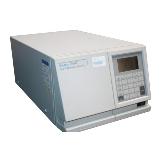
1.1 2487 Detector Description The Waters 2487 Dual λ Absorbance Detector (Figure 1-1) is a two-channel, tunable, ultraviolet/visible (UV/Vis) detector designed for high-performance liquid chromatography (HPLC) applications. Inlet TP01497 Figure 1-1 Waters 2487 Dual λ Absorbance Detector 2487 Detector Description... - Page 26 The Waters 2487 Dual λ Absorbance Detector can operate either as a stand-alone unit (with a chart recorder or integrator) or as an integral part of a Waters chromatography system. The Waters 2487 Dual λ Absorbance Detector can be configured with the following Waters systems: •...
-
Page 27: Principles Of Operation
• Wavelength verification and test • Flow cell • Electronics 1.2.1 Waters 2487 Detector Optics The Waters 2487 Dual λ Absorbance Detector optics are based on a Fastie Ebert tunable monochromator and include the following: • Deuterium (D ) lamp •... -
Page 28: Waters 2487 Dual Λ Absorbance Detector Optics Assembly
• Waters TaperSlit™ Flow Cell (its entrance is the exit slit of the monochromator) • Cuvette holder Figure 1-2 shows a diagram of the 2487 Detector optics assembly light path and components. Lamp Spherical Mirror Filter Window Wheel Slit Ellipsoidal... -
Page 29: Wavelength Verification And Test
2. The beamsplitter, located just ahead of the flow cell, diverts a portion of the light to a reference photodiode. 3. When you enter a new wavelength through the 2487 Detector’s front panel (or through the Millennium software or other system software control), the detector rotates the grating to the appropriate position. -
Page 30: Waters Taperslit Flow Cell
An additional feature of the Waters TaperSlit Flow Cell and the reason for its name is the shape of the flow cell entrance, which matches the shape of the entrance slit. -
Page 31: Comparison Of Flow Cell Characteristics
1-3, in a conventional cell, light bends and hits the wall of the flow cell. Four beams go in, only two come out. In the Waters TaperSlit Analytical Cell, the combination of the lens and TaperSlit bore geometry prevents light from hitting the cell walls. - Page 32 The behavior of the filter depends on the filter time constant that you select. The filter time constant adjusts the filter response time to achieve an optimal signal-to-noise ratio. Lower time constant settings: • Remove less baseline noise • Produce narrow peaks with minimal peak distortion and time delay •...
-
Page 33: Waters 2487 Dual Λ Absorbance Detector Electronics
• IEEE-488 interface – IEEE-488 communication allows the 2487 Detector to communicate with other Waters modules that have the IEEE-488 interface capability and the appropriate software. • Keypad – Allows you to access the control system, program methods, calibrate, and troubleshoot the 2487 Detector. -
Page 34: Operational Modes
• DC power supply – Provides voltage for the analog and digital circuitry. It is the dc power source for the detector. 1.3 Operational Modes The 2487 Detector operates in single or dual wavelength mode, allows spectrum scanning using a flow cell or a cuvette, and provides RatioPlot, difference plot, and MaxPlot functions. -
Page 35: Dual Wavelength Mode
– Reference energy: You can select reference energy for charting out the analog output. Scaling for reference energy is fixed at 150 nA/V. • Sensitivity in AUFS – This value specifies the scaling factor for the analog output channels and corresponds to the AU value where the analog outputs saturate at full scale values. - Page 36 Attention: In dual wavelength mode: STOP • If both selected wavelengths are greater than 370 nm, the detector applies the second order filter to block unwanted UV light. • If both selected wavelengths are less than or equal to 370 nm, the detector removes the second order filter.
-
Page 37: Spectrum Scanning
• Difference Plot (A-B or B-A) – This mode plots the arithmetic difference in absorbance for the two monitored wavelengths. 1.3.3 Spectrum Scanning Attention: When the 2487 Detector is operating under the control of the MIllennium³² STOP software, the scanning function is disabled. You can use the 2487 Detector as a spectrophotometer to acquire spectra from either the flow cell or the cuvette. -
Page 38: Ratioplot
2. A sample (absorbance) scan, which measures the absorbance of the analyte dissolved in mobile phase. The 2487 Detector subtracts the zero scan from the sample scan to create a sample spectrum. Since the cuvette scan is acquired by measuring the absorbance from a light path that includes both the flow cell and the cuvette, the solvent conditions in the flow cell should be identical for both scans. -
Page 39: Installing The 2487 Detector
® 2487 Dual λ Absorbance Detector requires connections to electrical power The Waters and to sample and waste lines to operate in any standard laboratory environment. This chapter describes how to install the 2487 Detector and connect it to the electrical supplies and to other equipment in an HPLC system. - Page 40 (if applicable) on file. Verification ensures proper operation of the detector optics and electronics. See Section 3.3.2, Verifying the Detector, for verification procedures. illustrates the size and the physical characteristics of the Waters 2487 Dual λ Figure 2-2 Absorbance Detector. 8.2 inches (20.8 cm) 19.8 inches (50.3 cm) 11.2 inches (28.4 cm)
-
Page 41: Site Selection And Power Requirements
2.2 Site Selection and Power Requirements 2.2.1 Site Selection Install the Waters 2487 Dual λ Absorbance Detector in an area that meets the requirements listed in Table 2-1. Table 2-1 Installation Site Requirements Parameter Requirement 4 to 40 °C (39 to 104 °F) Operating temperature range –40 to 70 °C (–104 to 158 °F) -
Page 42: Power Requirements
• Minimal power transients and fluctuations. • Line voltage of 100 to 240 Vac. Power consumption is 145 volt amps (VA). The Waters 2487 Detector operates in a nominal voltage range of 100 to 240 Vac, and requires a 3.15 A fuse. -
Page 43: Unpacking
If you see any damage or discrepancy when you inspect the contents of the carton, immediately contact the shipping agent and Waters Technical Service at 1-800-252-4752, U.S. and Canadian customers only. Other customers, call your local Waters subsidiary or your local Waters Technical Service Representative, or call Waters corporate headquarters for assistance at 1-508-478-2000 (U.S.). -
Page 44: Making Fluidic Connections
2.4 Making Fluidic Connections Before initial startup of the Waters 2487 Dual λ Absorbance Detector, you must complete: 1. The fluidic connections described in this section. 2. The electrical connections described in Section 2.5, Making Electrical Power Connections. Caution: Observe safe laboratory practices when handling solvents. Refer to the Material Safety Data Sheets for the solvents in use. - Page 45 Outlet Inlet TP01504 (labeled) Figure 2-3 2487 Detector Fluidic Connections Assembling the Fittings To assemble each fitting: 1. Slide the compression screw over the tubing end, followed by the ferrule (Figure 2-4). 2. Mount the ferrule with its taper end facing the end of the tubing (Figure 2-4).
-
Page 46: Ferrule And Compression Screw Assembly
Compression screw Ferrule Tubing End (straight and Tube smooth to achieve maximum column efficiency) Distance (determined by each application, such as union or column fitting) TP01139 Figure 2-4 Ferrule and Compression Screw Assembly Making Connections To make connections at the column outlet and detector inlet, and at the detector outlet: 1. -
Page 47: Making Electrical Power Connections
(Figure 2-5). 2. Plug the other end of the power cord into a properly grounded ac power source. 2487 Detector Rear Panel The 2487 Detector connects to other Waters components through rear panel electrical connections (see Figure 2-5). Inputs and... - Page 48 • IEEE-488 interface bus – The IEEE-488 bus connection, on the rear panel of the detector (see Figure 2-5), allows remote control and direct data acquisition from Waters Millennium® and MassLynx™ workstations, as well as remote control ® using the Waters Alliance and PowerLine™ compatible solvent delivery systems. Installing the 2487 Detector...
-
Page 49: Making Signal Connections
2.6 Making Signal Connections The rear panel of the 2487 Detector (see Figure 2-5) provides two analog connectors and an IEEE-488 communications port for operating the detector with external devices. The signal connections you need to make to your 2487 Detector depend on the: •... -
Page 50: Making I/O Signal Connections
Figure 2-6 shows an overview of the steps involved in making signal connections to the 2487 Detector. Start signal connection procedure Connect to IEEE-488 Install IEEE-488 cable bus? Connect to non-IEEE instru- Install event and I/O ment, such as integrator, chart cable(s) recorder, Bus SAT/IN, fraction collector, etc.? -
Page 51: I/O Signal Inputs And Outputs
B (Inputs and Outputs) A (Inputs) 1 ChA 2 V 1 Inject Start + 2 ChA 10 mV 2 Inject Start – 3 ChA Ground 3 Ground 4 Ground 4 Lamp On/Off + 5 ChB 2 V 5 Lamp On/Off – 6 ChB 10 mV 6 Ground 7 ChB Ground... -
Page 52: Connecting The 2487 Detector To A 2690 Separations Module In A Stand-Alone Configuration
2.6.2 Connecting the 2487 Detector to a 2690 Separations Module in a Stand-Alone Configuration You can connect the 2487 Detector to the Waters 2690 Separations Module, when it is not under the control of the Millennium³² software, to perform the following: •... - Page 53 To generate the auto zero function on the 2487 Detector at the start of an injection, make the connections summarized in Table 2-3 and illustrated in Figure 2-8. Table 2-3 2487 Detector Connections to a Waters 2690 Separation Module to Generate Auto Zero on Inject 2690 Separations Module 2487 Detector (B Inputs and Outputs) (A Inputs)
- Page 54 To generate the chart mark function on the 2487 Detector at the start of an injection, make the connections summarized in Table 2-4 and illustrated in Figure 2-9. Table 2-4 2487 Detector Connections to a Waters 2690 Separation Module to Generate Chart Mark on Inject 2690 Separations Module 2487 Detector (B Inputs and Outputs) (A Inputs)
-
Page 55: Starting A Method
Separations Module, make the connections summarized in Table 2-5 and illustrated in Figure 2-10. Table 2-5 2487 Detector Connections to a Waters 2690 Separation Module to Start a Method 2690 Separations Module 2487 Detector (B Inputs and Outputs) (A Inputs) - Page 56 Waters 2690 Waters 2487 B (Inputs and Outputs) A (Inputs) Inject Start Inject Start Inject Start Inject start Ground Ground Lamp On/Off Stop Flow + Lamp On/Off Ground Stop Flow – Chart Mark + Hold Inject 1 + Chart Mark –...
- Page 57 2690 Separations Module by making the connections in Table 2-6 and shown in Figure 2-11. Table 2-6 2487 Detector Connections to a Waters 2690 Separation Module to Turn the Detector Lamp On or Off 2690 Separations Module 2487 Detector (A Outputs)
-
Page 58: Making Ieee-488 Connections In Breeze And Millennium³²
When operating with these systems, the 2487 Detector emulates two separate 486 Detectors on the IEEE-488 communications bus, when the Detector is in dual wavelength mode. When connecting via the IEEE-488 to these Waters data systems, you should be aware that: •... - Page 59 4.0 AUFS. To connect IEEE-488 cables from the 2487 Detector to a Waters data system: 1. Connect the single receptacle end of the IEEE-488 cable (supplied with the Waters data system) to your data system: • Millennium or Millennium³² Chromatography Manager – Attach the cable to...
-
Page 60: Ieee-488 Connections To The 2487 Detector In A Waters
1500 Series Autosampler Detector Pumps Figure 2-12 IEEE-488 Connections to the 2487 Detector in a Waters Millennium System Note: When connecting the 2487 Detector to a data system, all detector parameters not configurable by the data system in use defer to local control. -
Page 61: Ieee-488 Connections To The 2487 Detector In An Alliance System
(the PowerLine controller manages the IEEE-488 interface functions). To set up the PowerLine controller, refer to the Waters 600E Multisolvent Delivery System User’s Guide, Section 4.1, Setting Up the 600 as a PowerLine Controller, or to the specific PowerLine component operator’s guide. -
Page 62: Powerline Controller Ieee-488 Connections
PowerLine Controller IEEE-488 Cable 717plus 2487 Autosampler Detector Figure 2-14 PowerLine Controller IEEE-488 Connections 4. Repeat steps 2 and 3 for each additional PowerLine component. Attention: The maximum total cable length between IEEE-488 devices is 65 feet STOP (20 meters). The maximum recommended cable length between two IEEE-488 devices is 13 feet (4 meters). - Page 63 When the 2487 Detector is operating in dual wavelength mode and connected to Millennium software versions lower than 3.0, PowerLine, or a Waters 2690 Alliance Separations Module version 1.15 or lower using the IEEE-488 communications bus, you must enable the Emulate dual 486 configuration option.
-
Page 64: Connecting To Other Devices
You can connect the 2487 Detector to a wide range of HPLC system devices. This section describes how to connect the 2487 Detector to the following devices: • Millennium using the bus SAT/IN™ Module • Waters 745/745B/746 Data Module • Chart recorder • Waters 600 Series Pump • Waters 717plus Autosampler •... -
Page 65: Connecting The 2487 Detector To The Millennium³² System Using The Bussat/In Module
To connect the 2487 Detector to the Millennium workstation: 1. Connect the busSAT/IN Module to the busLAC/E or LAC/E card in the Millennium computer, according to the instructions in the Waters Bus SAT/IN Module Installation Guide. Connecting to Other Devices... - Page 66 To ensure proper startup of the busSAT/IN Module, do not turn power on to STOP the module until you perform all procedures described in the Waters Bus SAT/IN Module Installation Guide. Improper startup can damage the unit and void the warranty.
-
Page 67: Bussat/In Module Channel 1 Connection To 2487 Detector Channel A
B (Inputs and Outputs) ChA 2V White ChA 10 mV ChA Gnd Ground ChB 2V Black ChB 10 mV Waters Bus SAT/IN Module ChB Gnd EVENTS CH 2 Switch 1 Switch 1 + – + – + – + –... -
Page 68: Connecting The 2487 Detector To A 745/745B/746 Data Module
Pin 7 ChB Ground (black) 2.7.2 Connecting the 2487 Detector to a 745/745B/746 Data Module You can connect the 2487 Detector to a Waters 745/745B/746 Data Module using the analog output connector on the rear panel of the detector. The analog connector provides both 2 V and 10 mV outputs which are scaled to the AUFS sensitivity setting and the voltage offset setting. - Page 69 Table 2-8 2487 Detector Connections to a Waters 745/745B/746 Data Module 2487 Detector 745/745B/746 (B Inputs and Outputs) Terminal Pin 1 ChA 2 V (red) Pin 3 ChA Ground (black) – Pin 5 ChB 2 V (red) Pin 7 ChB Ground (black) –...
-
Page 70: Waters 745/745B/746 Data Module Connections To 2487 Detector Channels A And B
ChB 2V – ChB 10 mV Waters 745/745B/746 ChB Gnd Terminals Switch 1 Switch 1 Ground Switch 2 Switch 2 TP01486 TP01486 Figure 2-17 Waters 745/745B/746 Data Module Connections to 2487 Detector Channels A and B Installing the 2487 Detector... -
Page 71: Connecting The 2487 Detector To A Chart Recorder
2.7.3 Connecting the 2487 Detector to a Chart Recorder Recorder Signal The A and B terminals on the rear panel of the 2487 Detector provide 2 V and 10 mV analog output signals that you can use to connect the 2487 Detector to a chart recorder. To send 2 V or 10 mV signals from the 2487 Detector to a chart recorder, use the cable provided in the 2487 Startup Kit to make the connections summarized Table 2-9... - Page 72 Waters 2487 A (Inputs and Outputs) ChA 2V ChA 10 mV Black ChA Gnd Ground ChB 2V – ChB 10 mV Chart Recorder ChB Gnd Switch 1 Switch 1 Ground Switch 2 Switch 2 TP01487 TP01487 Connecting to Channel A (2 V)
- Page 73 Connect the 2487 Detector to a chart recorder using the 10 mV analog connections as shown in Figure 2-19. Waters 2487 A (Inputs and Outputs) ChA 2V ChA 10 mV Black ChA Gnd Ground ChB 2V – ChB 10 mV...
-
Page 74: Connecting The 2487 Detector To The Waters 600 Series Pump
• You program a timed event to generate a chart mark. 2.7.4 Connecting the 2487 Detector to the Waters 600 Series Pump To connect the 2487 Detector to the Waters 600 Series Pump, locate the 2487 Detector in a position that satisfies the site requirements in Section 2.2, Site Selection and Power... -
Page 75: Waters 600 Series Pump And 2487 Detector Auto Zero Connections
2. Program the 600 Series Pump to provide a pulse output on the applicable switch (S1, S2, or S4) at the beginning of each run. Refer to the Waters 600E Multisolvent Delivery System User’s Guide, Section 5.1.2, for more details. -
Page 76: Waters 600 Series Pump And 2487 Detector Chart Mark Connections
2-21. 2. Program the 600 Series Pump to provide a pulse output on the selected switch at the beginning of each run. Refer to the Waters 600E Multisolvent Delivery System User’s Guide, Section 5.1.2, for more details. Table 2-12 Waters 600 Series Pump and 2487 Detector Chart Mark Connections... - Page 77 2487 Detector to initiate the start of data acquisition. To make inject start connections between the Waters 600 Series Pump and the 2487 Detector to start a method: 1. Using a signal cable, make the connections between the 2487 Detector and the...
-
Page 78: Waters 600 Series Pump And 2487 Detector Inject Start Connections
Table 2-13 Waters 600 Series Pump and 2487 Detector Inject Start Connections Waters 2487 Detector Waters 600 Series Pump A (Inputs) Terminal Pin 1 Inject Start + S1, S2, or S4 Pin 2 Inject Start – GND (one of four) -
Page 79: Connecting The 2487 Detector To The Waters 717Plus Autosampler
2.7.5 Connecting the 2487 Detector to the Waters 717plus Autosampler The Waters 717plus Autosampler signals the start of an injection through a contact closure signal on its Inject Start terminals. You can use this contact closure signal to command the 2487 Detector to perform an auto zero at the start of an injection. -
Page 80: Waters 717Plus Autosampler And 2487 Detector Inject Start Connections
To program an inject start, make the connections described in Table 2-15 and illustrated in Figure 2-25. Table 2-15 Waters 717plus Autosampler and 2487 Detector Inject Start Connections 2487 Detector 717plus Autosampler (A Inputs) Terminal Pin 1 Inject Start +... -
Page 81: Connecting The 2487 Detector To A Fraction Collector
Figure 2-25 illustrates the connections between the 2487 Detector and the Waters 717plus Autosampler. Use any available pair of Inject Start terminals on the 717plus Autosampler. Waters 2487 Waters 717plus A (Inputs) Inject Start Inject Start Ground Lamp On/Off Lamp On/Off... -
Page 82: Fraction Collector To 2487 Detector Connections
Pin 7 External Count In + B (Inputs and Outputs) Pin 8 B (Inputs and Outputs) Pin 10 Pin 8 External Count In – Ground Waters 2690 Separations Module/717plus Autoinjector Inject Start + External Start In + Inject Start – External Start In –... -
Page 83: Using The 2487 Detector
3.1 Starting Up the 2487 Detector 3.1.1 Initializing the 2487 Detector Before you power on the Waters 2487 Detector, be sure the connector from the 2487 Detector rear panel to the power source is properly installed. Starting Up the 2487 Detector... - Page 84 3-1). STARTUP DIAGNOSTICS GPIB QSPI Figure 3-1 Waters 2487 Detector Startup Diagnostics Display Following display of the Startup Diagnostics screen, the detector displays the following series of messages in sequence for about five minutes: • Initializing grating • Initializing system •...
-
Page 85: Diagnostics Failure
3.1.2 Diagnostics Failure If one or more of the internal startup diagnostics checks fails, the detector: • Beeps • Displays an error message • For serious errors, it displays the word “Error” in brackets (<Error>) in place of the run-time absorbance on the Absorbance screen. Section 5.1, Error Messages, for a list of startup diagnostics failures, error messages, and recommended recovery actions. -
Page 86: Absorbance And Message Screen Icons
Absorbance and Message Icons The Absorbance screens and message screens in the 2487 Detector program display the icons or fields shown in Figure 3-2 and described in Table 3-1. For a list of ranges and defaults for the function icons and fields described in Table 3-1, see Table... - Page 87 Table 3-1 Absorbance and Message Screen Icons (Continued) Icon or Field Icon / Field Name Function Shift On / Off Blank = Shift off s = Shift on λ = Detector operating in single wavelength Single / Dual Wavelength mode λλ...
-
Page 88: Using The Keypad
Table 3-1 Absorbance and Message Screen Icons (Continued) Icon or Field Icon / Field Name Function Next Indicates that pressing Next brings you to additional screens. Message screen icons (from left): Error, Question, Warning, Information, and Standby. 3.2.2 Using the Keypad The 2487 Detector keypad (Figure 3-3) consists of 24 keys providing:... - Page 89 λ/λλ Reset SCAN HOME Chart Mark Auto Zero Run/Stop METHOD Lamp Lock Calibrate System Info Previous CONFIGURE Contrast DIAG Next Scale TRACE Enter +/− Clear Field Cancel Shift Figure 3-3 2487 Detector Keypad Primary function keys take effect immediately, with no further entry required. Secondary function keys require you to enter information into parameter fields and to press Enter the functions to take effect.
- Page 90 Table 3-2 2487 Detector Keypad Description Description Unshifted Shifted HOME – Displays the Absorbance ? – Displays context-sensitive screen containing the icons, and help when available. HOME the Wavelength and AUFS fields. Chart Mark – Causes a SCAN – Displays the list of SCAN momentary pulse to the analog options for generating and...
- Page 91 Table 3-2 2487 Detector Keypad Description (Continued) Description Unshifted Shifted Next – Displays a screen with Previous – When the Next key is Previous additional options related to the available, Previous navigates Next current screen. Repeated through the screens in the reverse pressing of this key always brings order.
- Page 92 Table 3-2 2487 Detector Keypad Description (Continued) Description Unshifted Shifted 1 – See 0–9 above. Lamp – Displays the lamp use Lamp statistics for the currently installed lamp, and provides the ability to turn the lamp on or off. The current state of the lamp is indicated by an icon on the Absorbance screen.
-
Page 93: Navigating The User Interface
Table 3-2 2487 Detector Keypad Description (Continued) Description Unshifted Shifted +/– – Some edit fields accept • – Enters a decimal point. Also +/– positions the cursor at the last negative number entry. Use this • entry in a list. function to invert the sign of the number in the active field. - Page 94 Note: If you know the number corresponding to the desired choice, you can press that number without pressing Enter first. Note: The s and t keys do not increment or decrement numerical field entries. Use the numerical keypad. Navigating to and from the Absorbance Screen Pressing HOME brings you to the Absorbance screen from most screens.
-
Page 95: Primary And Secondary Functions
Setting Up a Run Once you press HOME to return to the Absorbance screen and select a wavelength mode (λ or λλ), you are ready to set the detector up for a run. In addition to wavelength mode, you must program the following parameters before beginning a run: •... - Page 96 • Log absorbance – Charts small and large peaks on a single chromatographic output. In this mode, voltage offset is used but absorbance offset is ignored. For the 2 V output: Volts out = (Log [Absorbance + 1] * 2 V) + voltage offset •...
- Page 97 Analog out (dual λ) – In addition to the selections for single λ above, you can chart the same parameters on the other channel at a different wavelength, and you can chart the following parameters: • MaxPlot – Charts the absorbance of multiple compounds with different absorbances at two different wavelength on a single data channel.
- Page 98 See the discussion “Filtering Noise” Section 1.2.3, Waters TaperSlit Flow Cell, for more information. Absorbance offset – Provides an offset in absorbance for adjusting the analog output. The default setting of 0.0 for absorbance offset charts 0.0 AU at 0.0 V. An absorbance offset of 1.0000 offsets the charted absorbance by 1.0000 AU.
- Page 99 Enable keypad & event-in chart mark – Selected by default, this parameter results in a chart mark each time one is requested via contact closure or through the front panel. You can disable this parameter by pressing any numerical key to deselect this box for either or both channels.
- Page 100 Table 3-3 Primary and Secondary Function (Method) Parameters Function Screen Type Units Range Default λ numeric integer 190 nm to 254 nm (wavelength (Absorbanc 700 nm e screen) AUFS numeric AUFS 0.0001 to 4.0000 2.0000 filter type 2 (of 4 or 5) choice none Hamming...
- Page 101 Table 3-3 Primary and Secondary Function (Method) Parameters (Continued) Function Screen Type Units Range Default voltage 3 (of 4 or 5) numeric integer –2000 to offset 2000 chart 3 (of 4 or 5) choice none polarity – Auto zero 4 (of 4 or 5) check none Checked/not...
-
Page 102: Operating The Trace And Scale Functions
3.2.5 Operating the Trace and Scale Functions The Trace function allows you to display an absorbance trace for the last n minutes (up to 60) of detector operation. • When you press the TRACE key, the 2487 Detector displays the absorbance acquired over the last 30 minutes by default. - Page 103 Figure 3-6 shows a 5-minute scaled trace (or zoom) of the 60 minutes of continuous injections shown in Figure 3-5. T1 is changed to –5. T2 is changed to 0. AU1 and AU2 remain as “auto.” Figure 3-6 Scaled Trace for 5 Minutes of Continuous Injections with T1 Changed to –5 Figure 3-7 shows a 60-minute scaled trace similar to that shown in Figure 3-5...
-
Page 104: Operating Other Detector Functions
3.2.6 Operating Other Detector Functions Configuring the 2487 Detector The 2487 Detector is configured at IEEE-488 remote address 4 by default. To change the default, you need to access the Configuration screens. Press the CONFIGURE (Shift DIAG). The first of three Configuration screens appears (Figure 3-9). - Page 105 • Emulate dual 486 – This option allows the 2487 Detector to appear on your external controller as two Waters 486 Detectors. This option provides for control and data acquisition of the 2487 Detector’s dual wavelength capabilities on older Waters...
- Page 106 • Chart mark – You can specify the Chart mark input to create a chart mark on Channel A and/or Channel B. You determine the response of the channel using the enable chart mark function explained in Table 3-3 and shown in Figure 3-4.
- Page 107 • Rectangular wave (in seconds) – If SW1 or SW2 is programmed to initiate a rectangular wave as a timed or threshold event, then the period of the signal (the width of one pulse period in a rectangular wave or pulse train) is as specified in this field (range is 0.2 to 60 seconds).
- Page 108 Displaying System Info System Info (Shift 4) displays information about the 2487 Detector, including the serial number, the software version number, and the IEEE address, if applicable (Figure 3-12). Single Wavelength Mode Dual Wavelength Mode Figure 3-12 System Info Screen Examples Using Help The 2487 Detector has limited context-sensitive help.
-
Page 109: Operating The 2487 Detector
• Set a different time constant Table 3-3 for more information on operating parameters in either single or dual wavelength mode. When the 2487 Detector is under the control of older Waters data systems, it functions as a Waters 486 Detector (see the discussion “Remote Control”). -
Page 110: Verifying The Detector
Remote Control To operate as part of a Waters Alliance system or under Millennium³² control, the 2487 Detector uses the IEEE-488 bus connector (see Section 2.6.3, Making IEEE-488 Connections in Breeze and Millennium³²). Under the control of the Millennium Chromatography Manager version 2.15 or lower, a 2690 Alliance Separations Module version 1.15, or a PowerLine controller, the 2487... - Page 111 Installing the 2487 Detector, for complete information on connecting the 2487 Detector to external devices. 2. Turn on the Waters 2487 Detector. The front panel displays a series of initialization messages for about five minutes. Refer to Section 3.1, Starting Up the 2487 Detector.
- Page 112 2. Press DIAG 2, Sample & ref energy, and record the sample and reference energies for 230 nm for later comparison. The Sample and Reference Energy Diagnostic display appears (Figure 3-14). Figure 3-14 Sample and Reference Energy Diagnostic Display 3. Record the numbers for later comparison. Note: Always run this procedure each time you change the 2487 Detector lamp.
-
Page 113: Wavelength Calibration
3.3.3 Wavelength Calibration The 2487 Detector offers you the option of calibrating the detector manually from the keypad. You can use the manual calibration key to recalibrate the detector at any time during operation, or if there are any calibration errors during startup. You do not have to reboot the detector after a successful wavelength calibration. -
Page 114: Operating The Detector In Single Wavelength Mode
A “Calibration complete” message is displayed momentarily. Other messages such as “Optimizing system performance” and “Restoring last setup” may appear before the display returns to the Absorbance screen. Note: If calibration is successful, the error message (<Error>) that was displayed on the Absorbance screen before you recalibrated the detector disappears. -
Page 115: Operating The Detector In Dual Wavelength Mode
When the 2487 Detector is operating in dual wavelength mode and connected to a PowerLine controller, the Millennium Chromatography Manager version 2.15 or lower or the Waters Alliance 2690 Separations Module version 1.15 or lower using the IEEE-488 communications bus, you must enable the... - Page 116 Changing from Single to Dual Wavelength Mode To change from single to dual wavelength mode: 1. From the Absorbance (or HOME) screen when in single wavelength mode (the wavelength icon shows λ), press the λ/λλ key (Shift Auto Zero). This key toggles between single and dual wavelength modes.
- Page 117 We recommend that, when in dual wavelength mode, you select a wavelength pair either below or above 370 nm. If one or both of the selected wavelengths spans the 370 nm threshold, the 2487 Detector beeps three times and issues the warning message shown in Figure 3-19.
-
Page 118: Programming Timed Events, Threshold Events, And Methods
9. Enter the maximum ratio for the RatioPlot, then press Enter. 10. Return to the Absorbance screen by pressing the HOME key. Obtaining a MaxPlot The 2487 Detector allows you to obtain a MaxPlot by monitoring absorbance at two selected wavelengths, while plotting the maximum absorbance for each sample component. - Page 119 When the 2487 Detector is operating under remote control, that is, control by the Millennium³² software, the PowerLine controller, or an Alliance Separations Module, the remote icon (Table 3-1) containing an IEEE-488 address is displayed. Timed Events You can program up to 16 timed events to the nearest 0.01 minute. As you enter timed events, each new event is appended to the end of the timed event list.
- Page 120 Table 3-4 Timed Event Parameters (Continued) Specify Number Event Units Range or Default Channel switch 1 1. high high 2. low 3. pulse 4. rect wave switch 2 1. high high 2. low 3. pulse 4. rect wave threshold –4.0000 to 4.0000 or variable, depending on output selection To program a new timed event:...
- Page 121 10. Press Reset to reset the run clock to 0. If the 2487 Detector is under the control of the Waters 717plus Autosampler or another external device, the inject start programmed from that device runs the method. Note:...
- Page 122 Threshold Events You can program threshold events on both Channel A and Channel B to control the switch contact closure outputs, for example, when using a fraction collector. You can program the switch to change when the programmed output (absorbance, ratio, energy, etc.) on the 2487 Detector Channel A or B is above a specified threshold.
- Page 123 To program a threshold event: 1. Press the METHOD (Shift A/B) key on the 2487 Detector keypad. The Method choice list is displayed (Figure 3-20). 2. Press 2, Threshold events. An active field (AU) for entering the threshold is displayed. When you begin to enter a number in the AU field, additional fields are displayed (Figure 3-22).
- Page 124 Figure 3-23 Storing a Method, Method Number Field Attention: There is no warning message if the method number you select is already STOP being used by a previously stored method. When you enter a number and press Enter, the current method conditions are stored, overwriting any previous method stored in the same slot.
- Page 125 If you make a change to a timed or threshold event within a method, the asterisk is displayed (Method *) indicating that the method (*) is no longer the same as the stored method you retrieved in step 1. You can then store the method containing the altered event(s) in the same storage slot.
-
Page 126: Scanning Spectra
Clearing Events You may want to clear only timed or threshold events without resetting any other operating parameters. To clear all active timed or threshold events: 1. Return to the Method choice list by pressing METHOD (Shift A/B). 2. Press 6, Clear events. - Page 127 Note: When using the cuvette, if the contents of the flow cell change, you must rerun the zero scan. Before You Begin Before you run a spectrum scan, you need to specify the following parameters: • λ1 – Starting wavelength. Scanning begins at this wavelength. •...
- Page 128 Figure 3-26 shows two scans of anthracene overlaid. At a pace of 1000 nm/min, the overlaid scan (with open circles) shows a reduced number of points scanned, lowering the resolution in comparison with the original scan done at a pace of 100 nm/min. Anthracene scan at 100 nm/min and 1000 nm/min Wavelength Figure 3-26 Scan of Anthracene at 100 nm/min and 1000 nm/min...
- Page 129 Wavelength (in nm) Figure 3-27 Scan of Erbium Standard in a Cuvette from 190 nm to 600 nm at a Pace of 200 nm/min with Tickmarks Every 20 nm Wavelength (in nm) Figure 3-28 Scan of Erbium Standard in a Cuvette from 190 nm to 600 nm at a Pace of 200 nm/min Without Tickmarks You enter these parameters when you select the type of scan, either zero or sample.
-
Page 130: Scanning New Spectra
• You cannot change the starting and ending wavelength parameters or the pace parameter. When you run the zero scan, you set up the starting and ending wavelengths, pace, tickmarks, and sensitivity for both the zero scan and subsequent sample scans. You should try to run sample scans within 15 minutes of the baseline zero scan. - Page 131 • Press for sample scan, or press Enter to display the choice list. The detector displays two additional screens. • Press for zero scan, or press Enter to display the choice list. The detector displays three additional screens. All parameters are displayed on the first New scan screen for both a zero and a sample scan.
- Page 132 Zero Scan To program a zero scan: 1. Press SCAN, then 1, New scan, and press 2, Zero scan. 2. Press Next to advance to the second Zero Scan parameter screen. 3. Enter the starting wavelength for the zero scan, then press Enter. 4.
- Page 133 Zero Scan (Screen 1 of 4) Sample Scan (Screen 1 of 3) Zero Scan (Screen 2 of 4) Sample Scan (Screen 2 of 3) Sample Scan (Screen 3 of 3) Zero Scan (Screen 3 of 4) Zero Scan (Screen 4 of 4) Figure 3-30 Zero and Sample Scan Screens Scanning Spectra...
- Page 134 Sample Scan Note: Run the zero scan before running the sample scan. To ensure identical flow cell and solvent conditions, you should run the sample scan for the corresponding zero scan within 15 minutes of running the zero scan. To run a sample scan: 1.
- Page 135 After a brief pause, the detector displays a sample scan graphically (Figure 3-32). Figure 3-32 Sample Erbium Scan Graphical Display 5. Press Next to display up to four highest peaks scanned (if four are found) within the specified range. Figure 3-33 shows the display of the four highest peaks for the sample erbium scan shown in Figure...
- Page 136 Figure 3-34 Sample Erbium Scan with λ1 Changed to 225 nm and λ2 Changed to 600 nm 9. Once you have changed one or more scaling parameters, press Enter reformat the graphical display. 10. Once the scan is redisplayed, press Next to display the four highest peaks of the scaled scan...
- Page 137 Sample scan 200 nm to 400 nm –0.001 AU to 0.5 AU Anthracene Zoom of sample scan 200 nm to 300 nm –0.001 AU to 0.5 AU Anthracene, 230 to 270 nm λ2 changed to 300 nm Zoom of sample scan 230 nm to 270 nm –0.001 AU to 0.5 AU Anthracene, 250 nm...
-
Page 138: Storing A Spectrum
3.4.2 Storing a Spectrum Once you have run a spectrum, you can store it for later review, subtraction, or playback. You may store up to five spectra. To store a spectrum: 1. From the graphic display of a sample scan, return to the first Scan screen by pressing SCAN (Shift Chart Mark). -
Page 139: Reviewing A Stored Spectrum
3.4.4 Reviewing a Stored Spectrum Once you have stored a spectrum, you can retrieve it for review from one of the five available storage slots by selecting the Review option from the Scan choice list. To review a spectrum: 1. Press SCAN (Shift Chart Mark) to view the Scan choice list. -
Page 140: Replaying A Spectrum
3.4.6 Replaying a Spectrum You can play back the current spectrum or a stored spectrum in real time using the Real-time replay function on the Scan choice list. The 2487 Detector plays back the selected spectrum in real time both on the detector display and out the analog connector to the chart or A/D device in a data collection system. - Page 141 Aperture Frosted Sides of Cuvette Facing Up and Down TP01502 Figure 3-38 2487 Detector Cuvette Holder with the Cuvette Inserted Note: Because the scan is actually a composite of both the contents of the cuvette and the flow cell, you need to perform cuvette scans under identical flow cell conditions. If you store spectra and acquire new spectra for subtraction, you need to be aware of differences, if any, in flow cell conditions.
- Page 142 Cuvette Scanning Procedure To begin a cuvette scan: 1. Remove the 2487 Detector left front panel cover. 2. To remove the cuvette holder, slide it toward you (Figure 3-39). TP01500 Figure 3-39 Removing the Cuvette Holder 3. With the spring guide facing you, gently insert the cuvette (containing eluent) up under the guide, with the cap facing upward (into the holder) and the frosted sides of the cuvette facing up and down.
- Page 143 4. Gently guide the cuvette holder back into the flow cell assembly until it sits in position securely (Figure 3-40). TP01501 Figure 3-40 Replacing the Cuvette Holder 5. Reinstall the detector left front panel cover. Attention: To prevent invalid subsequent chromatographic results, be sure to STOP remove the cuvette from the 2487 Detector and replace the empty holder after running your cuvette scans.
-
Page 144: Scanning Using A Static Flow Cell
8. Use the storage, review, subtract and review, and replay functions to analyze the data obtained. 3.4.8 Scanning Using a Static Flow Cell Note: Before you scan using a static flow cell, be sure to remove the cuvette and replace the empty cuvette holder. - Page 145 • Display the hours and minutes the lamp has been turned on: – During the current run – Since installation To turn off the lamp manually from the detector front panel: 1. Press Lamp (Shift 1) from the keypad. The lamp control screen is displayed (Figure 3-41).
-
Page 146: Shutting Down The 2487 Detector
To turn on the lamp manually: 1. When there is an X through the lamp icon on the Absorbance screen, press Lamp (Shift 1). The lamp control screen is displayed again with 0 hours and 00 minutes in the “Lamp has been on” field. 2. - Page 147 Shutting Down the 2487 Detector To shut down the detector, press the On/Off switch located on the front lower-right corner of the unit. Scanning Spectra...
-
Page 148: Maintenance Procedures
Waters Technical Service For problems with HPLC equipment, computer software or hardware other than for the Waters 2487 Dual λ Absorbance Detector, consult the documentation for the applicable instrument or program. If you encounter a problem with the 2487 Detector that you cannot troubleshoot, contact Waters Technical Service at 1-800-252-4752, U.S. - Page 149 Since there are no user-serviceable parts inside the 2487 Detector, the top STOP cover should not be removed. However, some procedures require that you remove the left front panel cover which contains the Waters 2487 Dual λ Absorbance Detector nameplate. Note: You can use the left front panel cover to hold small parts when removing and replacing the 2487 Detector flow cell.
-
Page 150: Routine Maintenance
TP01498 Figure 4-1 View of the Waters 2487 Dual λ Absorbance Detector with the Left Front Panel Cover Removed 4.2 Routine Maintenance The Waters 2487 Dual λ Absorbance Detector requires minimal routine maintenance. To achieve optimal performance: 1. Replace solvent reservoir filters in your HPLC system regularly. -
Page 151: Inspecting, Cleaning, And Replacing Parts Of The Flow Cell
4.3 Inspecting, Cleaning, and Replacing Parts of the Flow Cell A dirty flow cell can cause baseline noise, decreased sample energy levels, calibration failure, and other problems with operation of the 2487 Detector. There are two phases in cleaning the flow cell: •... -
Page 152: Removing And Cleaning The Flow Cell
4.3.2 Removing and Cleaning the Flow Cell If flushing the flow cell is not effective, follow the procedures to remove the flow cell and inspect for dirty or broken windows or dirty gaskets. Clean and replace parts if necessary. Before removing the flow cell assembly, purge the flow cell with nitrogen and allow to dry as follows: 1. - Page 153 Save all parts after removal unless otherwise indicated. Most of the removed parts are needed when you reinstall a flow cell. Removing the Flow Cell Assembly To remove the flow cell assembly: 1. Power down the 2487 Detector. 2. After flushing and drying the flow cell (see Section 4.3.1, Flushing the Flow Cell), disconnect and cap the inlet and outlet LC tubing to the detector.
- Page 154 TP01507 Figure 4-3 Removing the Flow Cell Assembly Inspecting, Cleaning, and Replacing Parts of the Flow Cell...
- Page 155 To prevent contamination, use powder-free finger cots or gloves when STOP disassembling, inspecting, cleaning, or replacing parts within the Waters TaperSlit™ Flow Cell or when removing or replacing the flow cell within its assembly. The Waters patented TaperSlit Flow Cell consists of: •...
- Page 156 Cell Entrance TP01495 Figure 4-5 Waters TaperSlit Flow Cell For replacement parts for the Waters TaperSlit Flow Cell, use the Flow Cell Rebuild Kit (P/N WAS081346). Note: Use nitrogen to clean the flow cell. Use ethanol or methanol to clean the lenses and window.
- Page 157 Split Ring Cuvette Lens Cuvette Lens Screw Exit Window Screw Exit Window Holder Exit Window (flat) Cell Body Gasket Gasket Entrance Lens (curved) Entrance Lens Holder Entrance Lens Screw TP01520 Figure 4-6 Waters TaperSlit Flow Cell, Exploded View Maintenance Procedures...
- Page 158 Section 4.3.3.3, Rebuilding the Flow Cell. Note: Waters recommends that you replace the clear plastic gaskets each time you inspect and clean the flow cell. 1. Inspect each part of the flow cell removed in the procedure in Section 4.3.3.1, Disassembling the Flow Cell, for dirt.
- Page 159 To prevent contamination, use powder-free finger cots or gloves when STOP disassembling, inspecting, cleaning, or replacing parts within the Waters TaperSlit Flow Cell or when removing or replacing the flow cell within its assembly. The 2487 Detector is shipped with a standard analytical flow cell installed. Replace the flow cell when: •...
-
Page 160: Replacing The Lamp
5. Reconnect the inlet/outlet tubing to your LC system. 6. Power up the detector. 4.4 Replacing the Lamp Attention: Waters recommends that you change the 2487 Detector lamp when it STOP repeatedly fails to ignite, or when the detector fails to calibrate. See Table... - Page 161 Determining the longevity of “useful” lamp life can be difficult due to varying user requirements and individual lamp behavior. The Waters 2487 Detector uses a combination of front-end electronics and lamp optimization software that make the best use of the energy present to optimize instrument performance.
- Page 162 Ultimately, the detector’s performance is a function of the user’s unique application. Noise and drift measurements are appropriate for evaluating performance and setting the boundaries for acceptable sensitivity limits. Waters guarantees 2000 hours of lamp life or one year of operation, which ever comes first. The detector’s on-board diagnostics allow lamp usage to be recorded and the lamp serial number to be reported.
-
Page 163: Removing The Lamp
4.4.1 Removing the Lamp Caution: To avoid eye damage from ultraviolet radiation exposure, turn off the unit and strictly adhere to the following procedures while changing the lamp. Caution: Lamp housing becomes extremely hot during operation. To prevent burns to the skin, allow the lamp to cool for at least 30 to 60 minutes before removing. - Page 164 5. Loosen the two captive screws in the lamp base (Figure 4-9). 6. Pull the lamp assembly out of the lamp housing. 7. Gently pull the lamp out (Figure 4-10). Caution: Lamp gas is under slight negative pressure. To prevent shattering the glass, use care when disposing of the lamp.
-
Page 165: Installing The New Lamp
TP01510 Figure 4-10 Removing the Lamp 4.4.2 Installing the New Lamp Caution: To avoid the possibility of exposing your eyes to ultraviolet radiation, wear eye protection that filters ultraviolet light and keep the lamp in the housing during operation. Attention: Do not touch the glass bulb on the new lamp. - Page 166 3. Record the serial number located on a label attached to the lamp connector wire using the procedure in Section 4.4.3, Recording the New Lamp Serial Number. Attention: Make sure power to the 2487 Detector is off. STOP To install the new lamp: 1.
-
Page 167: Recording The New Lamp Serial Number
TP01511 Figure 4-11 Aligning the Lamp 4.4.3 Recording the New Lamp Serial Number Attention: Always run the Change Lamp diagnostic (see Section 5.2.2, Using the STOP Diagnostics, the “Using the Lamp, Display, and Keypad Diagnostics” discussion) after you install a new lamp. Attention: If you do not record the new lamp serial number following the procedure in STOP... - Page 168 2. Press 4, Lamp, display & keypad. 3. Press 1, Change lamp. Note: Be sure to enter the 9-digit lamp serial number and not the lamp part number when performing this procedure. 4. Enter the 9-digit serial number of the new lamp in the active field (Figure 4-12).
-
Page 169: Replacing Fuses
Figure 4-14 Lamp Serial Number Confirmation Message Attention: To run the verification procedures with the new lamp installed, recalibrate the STOP detector or recycle power to the 2487 Detector after replacing the lamp. 4.5 Replacing Fuses The fuse holder is located on the rear panel of the detector (Figure 4-15). - Page 170 Caution: To avoid the possibility of electrical shock, power down and unplug the instrument before checking the fuses. For continued protection against fire hazard, replace fuses only with those of the same type and rating. Identifying Faulty Fuses Suspect a faulty fuse if: •...
- Page 171 Figure 4-16 Removing and Replacing the Rear Panel Fuses and Fuse Holder Maintenance Procedures...
-
Page 172: Error Messages, Diagnostics, And Troubleshooting
• Messages requiring you to perform corrective action. These include messages encountered at startup, and during calibration or operation. • Messages requiring you to recycle power, then contact Waters Technical Service personnel if the error persists (see “Waters Technical Service”... - Page 173 Table 5-1 provides startup, calibration, and operating error messages, descriptions, and recommended actions you can take to correct the problem. Refer to Section 1.2.2, Wavelength Verification and Test, Section 3.3.2, Verifying the Detector, and Section 3.3.3, Wavelength Calibration, for verification and calibration information and procedures.
- Page 174 Table 5-1 Startup, Calibration, and Operating Error Messages (Continued) Error Message Description Corrective Action Lamp lighting failure The lamp failed to ignite. Recycle power to the 2487 Detector. Check lamp power connection. Replace lamp. Lamp external input A timed event or action Check contact closure status.
-
Page 175: Error Messages Preventing Operation
• There is no cuvette in the cuvette holder, and the empty cuvette holder is securely in place. • The flow cell is clean. • The left front panel door is shut securely. Recycle power to the 2487 Detector. If the fatal error persists, contact Waters Technical Service. Error Messages, Diagnostics, and Troubleshooting... - Page 176 Table 5-2 lists the error messages that require you to contact Waters Technical Service if recycling power does not correct the error. Table 5-2 Possibly Fatal Error Messages Error Message Description Corrective Action Electronic A/D failure Lamp optimization is Recycle power.
- Page 177 Corrective Action Electronic A/D failure Data acquisition via A/D Recycle power to the 2487 converters is Detector. interrupt-driven. If interrupt Contact Waters Technical is too long, problem with Service. data acquisition is indicated. System cannot respond Error occurs while unit is...
- Page 178 Corrective Action Filter initialization failure: Unit sensors cannot find Recycle power to the 2487 Erbium position erbium filter position. Detector. Contact Waters Technical Service. Grating initialization failure: Search for the home sensor Recycle power to the 2487 No home sensor failed.
-
Page 179: User-Selected Diagnostics
5.2 User-Selected Diagnostics 5.2.1 Overview You may operate several diagnostics for use in: • Troubleshooting the detector • Verifying the detector electronics and optics To perform user-selectable diagnostics: 1. Press the DIAG key from the 2487 Detector front panel. The detector displays the Diagnostics choice list (Figure 5-2). - Page 180 Wrench Icon Figure 5-3 Absorbance Screen with Sticky Diagnostic Active The user-selectable sticky diagnostics are: • Fix (Set) Voltage Output • Fix (Set) Absorbance Input • Generate Test Peaks • Optical Filter Override Note: Application of sticky diagnostics affects results. To clear changes to the voltage output or absorbance input, or to make a manual optical filter change, select 1 Reset diagnostics...
-
Page 181: Using The Diagnostics
3. Previous choices << 5.2.2 Using the Diagnostics The 2487 Detector employs both user-selectable and service diagnostics. You access user diagnostics by pressing the DIAG key. Only qualified Waters service personnel can access service diagnostics. Error Messages, Diagnostics, and Troubleshooting... - Page 182 Troubleshooting), you are unable to correct an error condition, please contact Waters Technical Service at 1-800-252-4752, U.S. and Canadian customers only. Other customers, call your local Waters subsidiary or your local Waters Technical Service Representative, or call Waters corporate headquarters for assistance at 1-508-478-2000 (U.S.).
- Page 183 • Generate test peaks. • Override the optical filter. To perform any of the Input & Output diagnostics, press DIAG Input & output. A choice list appears (Figure 5-5). Auto zero offsets Figure 5-5 Input and Output Diagnostic Choice List Displaying Auto Zero Offsets From the Input &...
- Page 184 Figure 5-7 Fix Absorbance Diagnostic This diagnostic sets the voltages on the analog output channels based on the current AUFS setting. This is a sticky diagnostic. Setting Fixed Voltage Output From the Input & Output choice list, press 3, Fix voltage, to select a voltage for the analog output.
- Page 185 Figure 5-9 Contact Closures & Events Diagnostic The Input & Output diagnostic allows real-time monitoring of the state of the contact closure inputs. A solid (filled in) circle indicates the contact closure is closed (ON = High). An open (empty) circle indicates the contact closure is open (OFF = Low).
- Page 186 When you press 3, the display fills from top to bottom and from right to left, then returns to the Lamp, display & keypad choice list. If the display does not completely fill either horizontally or vertically, contact your Waters service representative.
- Page 187 Using the Other 2487 Detector Diagnostics The user diagnostic screen provides two additional features. You can: • Generate test peaks – Use this diagnostic to specify the generation of test peaks to calibrate your chart recorder or data system. • Manually override the optical filter – Use this diagnostic to make a filter selection different from the detector’s normal operating mode.
- Page 188 This is a sticky diagnostic. When this diagnostic is enabled, the choice list changes to read “Disable test peaks.” 2. Press 1, Disable test peaks, from the Other diagnostics choice list, to turn this diagnostic off. Overriding the Optical Filter 1.
-
Page 189: Service Diagnostics
Most detector problems are relatively easy to correct. If you are unable to correct a problem or a failed condition, contact Waters Technical Service at 1-800-252-4752, U.S. and Canadian customers only. Other customers, call your local Waters subsidiary or your local Waters Technical Service Representative, or call Waters corporate headquarters for assistance at 1-508-478-2000 (U.S.). -
Page 190: Hardware Troubleshooting
Broken electrical Check electrical connections. fails to illuminate connection Fuse blown Check and, if necessary, replace fuse(s). Bad LCD or control Contact Waters Technical Service. board Front panel displays Faulty EPROMs Contact Waters Technical Service. odd characters Bad LCD control board... - Page 191 (external) Keypad not Keypad defective Recycle power to the 2487 Detector functioning and run the keypad diagnostic. Contact Waters Technical Service. Lamp life not Revision 1.0 firmware Upgrade to Revision 1.01 firmware. calculated properly in place. Contact Waters Technical Service.
- Page 192 250 nm. air bubbles Ensure there are no air bubbles in the flow cell. Recalibrate the 2487 Detector. If problems persist, contact Waters Technical Service. Analog output AUFS setting Reset the AUFS setting. incorrect...
-
Page 193: 2487 Detector Specifications
Appendix A 2487 Detector Specifications 2487 Dual λ ® This appendix lists individual operating specifications for the Waters Absorbance Detector, as shipped: • Table A-1 lists operational specifications. • Table A-2 lists optical specifications. • Table A-3 lists specifications for the optional flow cells. - Page 194 Table A-1 Operational Specifications (Continued) Condition Specification Filter setting range Single wavelength: 0.1 to 5.0 seconds, Hamming (default) 1 to 99 seconds, RC Dual wavelength: 1 to 50 seconds, Hamming (default) 1 to 99 seconds, RC Optical Component Specifications Lamp source Deuterium arc lamp Flow cell TaperSlit™...
- Page 195 Table A-1 Operational Specifications (Continued) Condition Specification Fuse ratings Two fuses: 100 to 240 Vac, 50 to 60 Hz F 3.15 A 250 V FAST BLO, 5 x 20 mm (IEC) Power consumption 145 VA (nominal) Two attenuated analog Attenuation range: 0.0001 to 4.000 AU 2 V output range: –0.1 to +2.1 V output channels: 10 mV output range: –0.5 to +10.5 mV...
- Page 196 Table A-2 Optical Specifications Fastie Ebert Monochromator Configuration Grating Plane holographic 1800 grooves/mm Optical bandwidth 5 nm Lamp power 30 W Table A-3 Optional Waters TaperSlit Flow Cell Specifications Sample Tube Path Volume Internal Pressure Length (µl) Diameter Rating (mm)
-
Page 197: Appendix B Spare Parts
Appendix B Spare Parts 2487 Dual λ Absorbance Detector. These ® Table B-1 lists the spare parts for the Waters spare parts are user-replaceable. Table B-1 Spare Parts Item Part Number Fuses Fuse, 3.15 A, 5 x 20 mm WAS163-16... - Page 198 Table B-1 Spare Parts (Continued) Item Part Number Two Cuvette Set (empty) WAT047689 Flow Cell Rebuild Kit, 10 mm WAS081346 Flow Cell Rebuild Kit, 3 mm WAS081347 MS Flow Cell Rebuild Kit 700000168 MS Flow Cell Gasket Kit 700000169 Gasket Kit, set of 10 WAS081348 2487 Qualification Workbooks WAT520-01...
-
Page 199: Appendix C Warranty Information
The Warranty covers all new products manufactured by Waters. Waters warrants that all products that it sells are of good quality and workmanship. The products are fit for their intended purpose(s) when used strictly in accordance with Waters’... - Page 200 Exclusive Remedy In the event of any failure of the Waters 2487 Dual λ Absorbance Detector to perform, in any material respect, in accordance with the warranty set forth herein, the only liability of Waters Corporation to Customer, and Customer’s sole and exclusive remedy, shall be the use, by Waters Corporation, of commercially reasonable efforts to correct for such deviations, in Waters Corporation’s sole discretion, replacement of the purchased Waters...
- Page 201 Warranty Service Warranty service is performed at no charge and at Waters’ option in one of three ways: • A service representative is dispatched to the customer facility. • The product is repaired at a Waters repair facility. • Replacement parts with appropriate installation instructions are sent to the customer.
- Page 202 Table C-1 summarizes the warranty periods for applicable components. Table C-1 2487 Detector Warranty Periods Item Warranty Waters 2487 Dual λ Absorbance Detector, 1 year excluding the components listed below Normal Wear and Maintenance Parts (in 2000 hours Performance Maintenance Kit...
-
Page 203: Shipments, Damages, Claims, And Returns
This request must be made within 15 days of receipt. Otherwise, the claim will not be honored by the carrier. Do not return damaged goods to the factory without first securing an inspection report and contacting Waters for a return merchandise authorization number (RMA). -
Page 204: Solvent Considerations
Appendix D Solvent Considerations Caution: To avoid chemical hazards, always observe safe laboratory practices when operating your system. D.1 Introduction Clean Solvents Clean solvents provide: • Reproducible results • Operation with minimal instrument maintenance A dirty solvent can cause: • Baseline noise and drift •... -
Page 205: Solvent Miscibility
Water Use water only from a high-quality water purification system. If the water system does not provide filtered water, filter it through a 0.45-µm membrane filter before use. Buffers When you use buffers, dissolve salts first, adjust the pH, then filter to remove insoluble material. - Page 206 Table D-1 Solvent Miscibility Boiling λ Cutoff Polarity Viscosity Miscibility Solvent Point °C Index CP, 20 °C Number (M) (nm) (1 atm) –0.3 N-decane 0.92 174.1 –– –0.4 Iso-octane 0.50 99.2 N-hexane 0.313 68.7 –– Cyclohexane 0.98 80.7 Butyl ether 0.70 142.2 ––...
- Page 207 Table D-1 Solvent Miscibility (Continued) Boiling λ Cutoff Polarity Viscosity Miscibility Solvent Point °C Index CP, 20 °C Number (M) (nm) (1 atm) Methyl ethyl ketone 0.43 80.0 Cyclohexanone 2.24 155.7 Nitrobenzene 2.03 210.8 14, 20 –– Benzonitrile 1.22 191.1 15, 19 ––...
-
Page 208: Buffered Solvents
How to Use Miscibility Numbers Use Miscibility numbers (M-numbers) to predict the miscibility of a liquid with a standard solvent (Table D-1). To predict the miscibility of two liquids, subtract the smaller M-number value from the larger M-number value. • If the difference between the two M-numbers is 15 or less, the two liquids are miscible in all proportions at 15 °C. -
Page 209: Head Height
D.4 Head Height Position the solvent reservoirs at a level above the HPLC equipment or on top of the pump or detector (with adequate spill protection). D.5 Solvent Viscosity Generally, viscosity is not important when you are operating with a single solvent or under low pressure. -
Page 210: Solvent Degassing Methods
Changes in the composition, temperature, or pressure of the mobile phase can all lead to outgassing. Effects of Intermolecular Forces Nonpolar gases (N , CO , He) are more soluble in nonpolar solvents than in polar solvents. Generally, a gas is most soluble in a solvent with intermolecular attractive forces similar to those in the gas (like dissolves like). - Page 211 To increase the length of membrane, you can connect two or more vacuum chambers in series. The in-line degasser is available as an option or factory-installed in the Waters 2690 Separations Module, XE model.
- Page 212 D.7 Wavelength Selection This section includes UV cutoff ranges for: • Common solvents • Common mixed mobile phases • Chromophores UV Cutoffs for Common Solvents Table D-2 shows the UV cutoff (the wavelength at which the absorbance of the solvent is equal to 1 AU) for some common chromatographic solvents.
- Page 213 Table D-2 UV Cutoff Wavelengths for Common Chromatographic Solvents (Continued) Solvent UV Cutoff (nm) Solvent UV Cutoff (nm) Dioxane Nitromethane Ethanol Petroleum ether Ethyl acetate Pyridine Ethyl ether Tetrahydrofuran Ethyl sulfide Toluene Ethylene dichloride Xylene Mixed Mobile Phases Table D-3 contains approximate wavelength cutoffs for some other solvents, buffers, detergents, and mobile phases.
- Page 214 Triton-X™ 100, 0.1% ® Hydrochloric acid, 0.1% Waters PIC Reagent A, 1 vial/liter MES, 10 mM, pH 6.0 Waters PIC Reagent B-6, 1 vial/liter Potassium phosphate, Waters PIC Reagent B-6, monobasic, 10 mM low UV, 1 vial/liter dibasic, 10 mM...
- Page 215 Table D-4 Electronic Absorption Bands of Representative Chromophores ∈ max λ max ∈ max Chemical λ max (nm) Chromophore Configuration (L/m/cm) (nm) (L/m/cm) Ether —O— 1000 Thioether —S— 4600 1600 Amine —NH 2 2800 Thiol —SH 1400 Disulfide —S—S— 5500 Bromide —Br Iodide...
- Page 216 Table D-4 Electronic Absorption Bands of Representative Chromophores (Continued) ∈ max λ max ∈ max Chemical λ max (nm) Chromophore Configuration (L/m/cm) (nm) (L/m/cm) —N=N— 285-400 3-25 Nitroso —N=O Nitrate —ONO 2 (shoulder Allene —(C=C) 2 — 210-230 21,000 (acyclic) Allene —(C=C) 3 —...
- Page 217 Index +/- key Alliance system connecting to ? key controlling from • • • • key IEEE-488 connections Analog outputs channel outputs connections A/B key dual wavelength Absorbance dual wavelength signal difference plot signal adjusting function single wavelength halted by fatal error single wavelength signal icon specifications...
- Page 218 Beamsplitter enabling Benefits of degassing generating Buffered mobile phase generating from the 2690 flushing timed event parameter removing Waters 600 Series Pump Buffered solvents connections busSAT/IN module, connecting to – Chart Mark key Chart polarity function parameter Chart recorder connections –...
- Page 219 Controlling Connecting to from data systems 2690 Separations Module – from Waters data systems Alliance system – the 2487 from older Waters data busSAT/IN module – systems chart recorder – Cooling off the lamp column Cover, removing electrical power –...
- Page 220 Degassing verification failure benefits Difference plot considerations – Diffraction grating solvents Dimensions Deleting a timed event Direct data acquisition Design Dirty flow cell electronic Disabling features external events optical inputs Deuterium lamp Disassembling the flow cell – installing Display optics absorbance replacement absorbance trace...
- Page 221 Enabling Exploded view of Waters TaperSlit Flow auto zero Cell auto zero parameter External events chart mark disabling chart mark event inputs enabling chart mark parameter Emulate dual 486 option external events Failure of startup diagnostics tests inputs Faulty fuses...
- Page 222 damaged analog outputs, dual wavelength description analog outputs, single wavelength – dirty auto zero disassembling auto zero on wavelength changes – exploded view dual wavelength mode flushing log absorbance frontal view MaxPlot gasket primary head-on view RatioPlot inspecting Scale – –...
- Page 223 HOME screen. See Absorbance screen Waters 600 Series Pump connections Waters 717plus Autosampler connections Input and output diagnostics I/O signals Inputs Icons disabling absorbance enabling channel selector signals keypad lock Inspecting lamp 2487 Detector local/remote control flow cells method number...
- Page 224 Enter key cooling time functions energy and performance Help key icon HOME key installing – illustration lamp, display and keypad λ λ λ λ /λλ λλ λλ key λλ diagnostics Lamp key monitoring aging Lamp, display and keypad – diagnostics removing –...
- Page 225 Miscibility of solvents – Mobile phase flushing Maintenance routine removing safety and handling Modes, changing safety precautions Monitoring Manual calibration – contact closures lamp aging Manual lamp procedures Mounting the detector Maximum ratio field Moving to the last entry in a list function parameter MaxPlot function...
- Page 226 auto zero offset diagnostic Parameters voltage absorbance offset absorbance threshold timed Operating event as a stand-alone instrument analog out (dual wavelength) detector – analog out (single wavelength) in dual wavelength mode – AUFS in single wavelength mode – auto zero on inject –...
- Page 227 Performing verification RC filter procedures – Rear panel Photodiodes fuses illustration Plus/minus key signal connections Polarity timed event parameter Reassembling the flow cell – Polarity, chart Rebuild kit, flow cell Power Rebuilding the flow cell – requirements surges Recalling the Absorbance screen using the HOME key Powering off Recording...
- Page 228 Reservoirs, positioning screens when to run Reset diagnostics Scale Reset key function – Resetting zooming run clock Scale key stored method Scaling factor Resolution, reduction in SCAN key Retrieving a method Scanning Returning to initial conditions anthracene Returns, warranty AUFS Reviewing a scan cuvette –...
- Page 229 Site requirements timed event parameter Size and physical characteristics Serial number Slit, entrance instrument Solvent lamp – buffered solvents Service contamination contacting Waters degasser diagnostics degassing exceptions to warranty filter warranty general considerations – Set absorbance diagnostic guidelines miscibility –...
- Page 230 wavelength accuracy Switch 2 timed event parameter wavelength range Switched outputs Spectra Switches comparing using the cuvette programming generating setting – System obtaining information about displaying information replaying flushing reviewing information scanning – specifications – scanning using a static flow cell System Info key storing subtracting...
- Page 231 Waters 600 Series Pump Scale function to zoom auto zero connections static flow cell for scanning chart mark connections the 2487 as a spectrophotometer configuring the detector lamp the 2487 with older Waters data signal systems connecting to –...
- Page 232 – starting a method from single/dual icon turning the 2487 lamp on or off starting from timed event parameter 600 Series Pump. See Waters 600 Series Wrench icon Pump Zero scan definition parameters running Index...
Need help?
Do you have a question about the 2487 Dual A and is the answer not in the manual?
Questions and answers