Table of Contents
Advertisement
Operation Manual
5.0
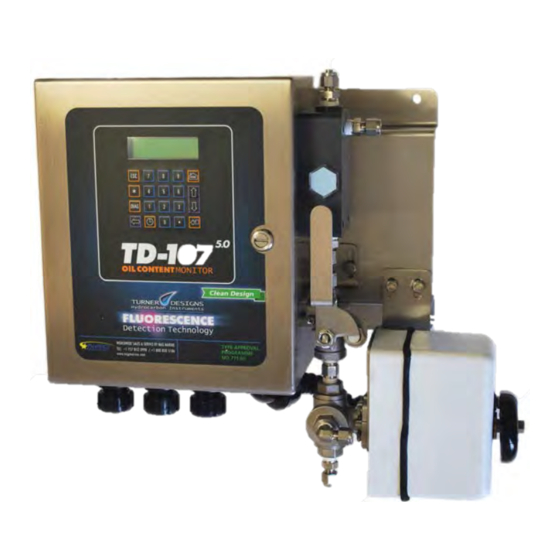
TD-107
Oil Content Monitor
DNV Type Approval Programme No. 771.61 Certified
January 28, 2015
P/N NAG2544 Rev. C
Applicable to TD-107 Serial Numbers 2000001F and greater.
Global Sales & Service Support:
NAG Marine
2511 Walmer Avenue
Norfolk, VA 23513
+1 800 830 5186
www.nagmarine.com
TD107Service@nagmarine.com
Approved Clean Bilge
Advertisement
Table of Contents
Troubleshooting

Related Manuals for Turner Designs TD-107 5.0


Summary of Contents for Turner Designs TD-107 5.0
- Page 1 Operation Manual TD-107 Oil Content Monitor DNV Type Approval Programme No. 771.61 Certified January 28, 2015 P/N NAG2544 Rev. C Applicable to TD-107 Serial Numbers 2000001F and greater. Global Sales & Service Support: NAG Marine 2511 Walmer Avenue Norfolk, VA 23513 +1 800 830 5186 www.nagmarine.com TD107Service@nagmarine.com...
- Page 2 TD-107 Oil Content Monitor Operation Manual THIS PAGE INTENTIONALLY LEFT BLANK...
- Page 3 TD-107 Oil Content Monitor Operation Manual To ensure proper system operation, NAG Marine strongly recommends reading this manual in full. After reading the entire manual, please review the following: Prior to installation, completely review the Pre-installation/ INSTALLATION Installation Checklist, Appendix A, page 31. Prior to start-up, completely review the Start-Up Section, START-UP page 10.
-
Page 4: Table Of Contents
TD-107 Oil Content Monitor Operation Manual 9.0. TD-107 OCM MAINTENANCE ..19 Table of Contents Battery Back-Up ......19 Preventative Maintenance ..19 INTRODUCTION ......5 Replacement Parts .....20 General ........5 10.0 ALARMS and ADVISORIES ..21 Symbols ........5 10.1 Alarm Delay .......21 THEORY OF OPERATION ..... -
Page 5: Introduction
TD-107 Oil Content Monitor Operation Manual to divert bilge water discharge in the event oil content exceeds 5 ppm. The TD-107 1.0 INTRODUCTION OCM also permits process monitoring through system-function relays, oil content This operations manual is relays, and analog sample concentration applicable to instruments with outputs. -
Page 6: Light Source
TD-107 Oil Content Monitor Operation Manual translated to a voltage response which oil while meeting DNV TAP NO. 771.61 corresponds to the concentration of performance criteria. fluorescent hydrocarbons in the sample. 2.5 Light Detector The TD-107 OCM contains five important components that it uses to make the The light detector produces a pulse of fluorescence measurement:... -
Page 7: Specifications
TD-107 Oil Content Monitor Operation Manual 3.0 SPECIFICATIONS Oil Types As per DNV TAP No. Measured: 771.61 requirements. NAG Marine Part Number: NAG2541 Scaled 0–30 ppm, as per Physical Specifications Measurement DNV TAP No. 771.61 17.375 in. W x 7.1875 in. D Range: requirements. -
Page 8: Mechanical Connections
TD-107 Oil Content Monitor Operation Manual The unit should not be installed: The outlet plumbing connections MUST NOT place stress on the 0.25 in. [6.35 mm] tube drain • Adjacent to known heat sources or in connection point. Damage to the direct sunlight;... -
Page 9: Power And Input/Output Signal Requirements
TD-107 Oil Content Monitor Operation Manual 4.5 Power and Input/Output Signal still indicate an alarm condition but Requirements overboard discharge will not cease. 4.5.4 Signal Output 4.5.1 Power One internally-powered 4–20 mA signal Required Power: 20-240 VAC, 50/60 Hz, (isolated) providing a 0.0–30.0 ppm 15 W or 20-240 VDC. -
Page 10: Start-Up / Shut-Down
TD-107 Oil Content Monitor Operation Manual 4.6.2 Disconnecting Wiring Connections 2. Apply power. When power is first turned on, an identification screen To disconnect a wire from the pre-wired will appear for a few seconds, cabling: showing the software version and 1. -
Page 11: Start-Up Sample Cell Maintenance And Cleaning
TD-107 Oil Content Monitor Operation Manual 5.3 Start-Up Sample Cell 5.3.2.1 Sample Cell Cleaning with Maintenance and Cleaning Detergent Proper maintenance and cleaning of the 1. Close the TD-107 inlet valve handle. TD-107 sample cell is a key component of MAINT MODE will be displayed on the consistent oil content monitoring. -
Page 12: Shut-Down Sample Cell Maintenance And Cleaning
TD-107 Oil Content Monitor Operation Manual 10. Open the TD-107 inlet valve. Ensure 8. If the ppm value has stabilized between MAINT MODE is no longer displayed 0–5 ppm AND the Cell Condition percentage has stabilized between 70– on the LCD. The instrument is now 100 %, the instrument is ready for ready to begin OWS operations. -
Page 13: Ocm Software
TD-107 Oil Content Monitor Operation Manual 7.0 TD-107 OCM SOFTWARE discharge/outlet piping is not pressurized. FUNCTIONS 2. Clean the unit by injecting 60 mL of cleaning solution into the sample cell The TD-107 OCM has menu driven with one of the provided 60 mL syringes. software that simplifies the user interface. -
Page 14: Keypad Functions
TD-107 Oil Content Monitor Operation Manual different measurements taken by the OCM 7.2.4 Escape Key <ESC> sensors. The <ESC> key is used from the HOME 7.1.6 Cell Condition and Zero Drift screen to view the current alarms. <ESC> is Correction also used to return to a previous screen or to exit a parameter change screen after the The cell condition and zero drift correction is... -
Page 15: Standby Mode
TD-107 Oil Content Monitor Operation Manual alarm. If after the alarm is triggered 10 7.2.7 <> Key minutes elapse with no record of a key pressed, the detection system will turn off This key initiates the Zero Adjust function of and the LCD will display a STANDBY the TD-107 OCM. -
Page 16: Data Retrieval
TD-107 Oil Content Monitor Operation Manual 8.2 Data Retrieval are set to Greenwich Mean Time (GMT) and cannot be changed. Perform the following steps to retrieve data The following alarms and indications are from the Datalogger: possible logged events within the 1. - Page 17 TD-107 Oil Content Monitor Operation Manual The “EVENTS.txt” data file is written first, followed by the “ALLDATA.txt” data file. A 512 MB minimum size data key for file retrieval is recommended. Any existing Datalogger (EVENTS.txt or ALLDATA.txt) files on the USB data key will be overwritten during the data retrieval process.
-
Page 18: Example
HiSTD_REF:0.000V, HiSTD_FL:0.000V, LoSTD_REF:0.000V, LoSTD_FL:0.000V LoSTD_REF:0.000V, LoSTD_FL:0.000V CalTemp:24.0C, CellCalTempco:0.643%/C CalTemp:24.0C, CellCalTempco:0.643%/C TD-107 5.0 OnTime:00000 Hrs, LED TD-107 5.0 OnTime:00000 Hrs, LED OnTime:00000 Hrs, H20TempMAX:0.1C OnTime:00000 Hrs, H20TempMAX:0.1C Hi Set: 5.0ppm, Early Set: 3.0ppm, Zero Hi Set: 5.0ppm, Early Set: 3.0ppm, Zero Set: 0.0ppm... -
Page 19: Td-107
TD-107 Oil Content Monitor Operation Manual 9.2 Preventative Maintenance 9.0. TD-107 MAINTENANCE Preventative maintenance should be performed to ensure optimum monitor Do not break the provided tamper operation and maximum life. The two evident DNV certification seals for maintenance actions that the user can any reason. -
Page 20: Replacement Parts
TD-107 Oil Content Monitor Operation Manual Be sure to move the inlet valve to the flow position after completing the cleaning. 9.2.3 Calibration Check The calibration should be checked using the provided Check Solution. If the Check Solution does not read within the allowed tolerance, clean the sample cell. -
Page 21: Alarms And Advisories
TD-107 Oil Content Monitor Operation Manual causes what appears to be a failure in 10.0 ALARMS and ADVISORIES another part of the unit. For example, putting the TD-107 OCM in Maintenance The primary purpose of the TD-107 Mode will trigger a Maintenance Mode is to act as an alarm to oil content greater Advisory and a Flow Alarm since the inlet than 5 ppm. -
Page 22: Alarm / Advisory Definitions
TD-107 Oil Content Monitor Operation Manual Table 3. Alarm Display / Delay Time Delay Alarm/Advisory As Displayed on LCD Condition time High (5 ppm) Signal HIGH OIL READING Oil Content > 5 ppm 0 sec Zero Signal ZERO OIL READING Oil Content = 0 ppm 0 sec LED Failure... -
Page 23: Troubleshooting
TD-107 Oil Content Monitor Operation Manual 10.5.8 Early Warning The troubleshooting procedure works best in this sequence: If the measured oil in water concentration 1. Handle any alarms first (see 10.0. exceeds the Early Warning set point Alarms and Advisories). (default is 3.0 ppm), EARLY WARNING will 2. -
Page 24: Display Screens
TD-107 Oil Content Monitor Operation Manual 11.2 Display Screens 11.2.3 SCREEN 3 (LED) 11.2.1 SCREEN 1 (Software Version) LED: ON 00231 Hours TD-107 SW: 104754 Diagnostics SCREEN 3 is a display of the LED status. • LED: ON indicates normal operating. Diagnostics SCREEN 1 is a display of the OFF indicates that the LED has failed or current software version. -
Page 25: Datalogger Failure
TD-107 Oil Content Monitor Operation Manual 11.2.6 SCREEN 6 • Low Std.: The fluorescence value for (PPM and Cell Condition) the low calibration standard stored from the last instrument calibration. For the ranges, and default values of these 10.0 PPM items, see Appendix E: Calibration Data Screen. -
Page 26: Troubleshooting Guide
TD-107 Oil Content Monitor Operation Manual 11.6 Troubleshooting Guide [HANDLE ANY ALARMS FIRST] SYMPTOM POSSIBLE CAUSE SOLUTION HOME screen displays 1. System Values are Check the Configuration Record over/OVER (blinking from over incorrect (i.e .Fluor Temp for the site. Access the System to OVER). - Page 27 TD-107 Oil Content Monitor Operation Manual Troubleshooting Guide (Continued) SYMPTOM POSSIBLE CAUSE SOLUTION HOME screen reads zero. System Values incorrectly Make sure valid System Values set, no water or clean water were entered (see Appendix F). running through the monitor. Screen blank or black.
-
Page 28: Responsibility For Safe Delivery
TD-107 Oil Content Monitor Operation Manual 12.0 RESPONSIBILITY FOR SAFE DELIVERY NAG Marine has done everything possible to protect this equipment from damage due to normal transportation hazards. After the product leaves the manufacturing site, responsibility for its safe handling and delivery is assumed by the transportation company handling the equipment. -
Page 29: Legal & Warranty
Turner Designs Hydrocarbon Instruments, Inc. and/or NAG Marine. 13.2 Trademarks TD-107 Oil Content Monitor (Bilge Alarm) is a trademark of Turner Designs Hydrocarbon Instruments, Inc. Other brand and product names are trademarks and/or registered trademarks of their respective holders. 13.3 Right of Change Information in this document is subject to change without notice and does not represent a commitment on the part of Turner Designs Hydrocarbon Instruments, Inc. - Page 30 You must obtain a RMA number prior to shipping the monitor. The monitor will be repaired and returned free of charge if the damage is covered by the warranty. This warranty service is provided to NAG Marine and Turner Designs Hydrocarbon Instruments’ users in the contiguous continental United States.
-
Page 31: Installation Checklist
TD-107 Oil Content Monitor Operation Manual APPENDIX A INSTALLATION CHECKLIST CUSTOMER INFORMATION: To be completed by Service Technician Customer:____________________________________ Date: ____________________ Location:_______________________________________________________________ System Name: __________________________________________________________ Estimated Start-up Date: __________________________________________________ Service Technician Name: _________________________________________________ Service Technician Telephone Number: ______________________________________ Type of oil being detected: _________________________________________________ CHECKLIST The following checklist is provided so the appropriate preparations may be made prior to equipment start-up. - Page 32 TD-107 Oil Content Monitor Operation Manual INSTALLATION CHECKLIST To Do Complete Requirements INITIAL REQUIREMENTS -- WATER ENGINEER Ensure turbidity is less than 50 NTU. (NOTE: Install appropriate filter/strainer on inlet if required). ° ° Assure bilge water temperatures of 32–140 F [0–60 INSTALLATION REQUIREMENTS -- WATER ENGINEER Locate unit within 25 ft [7.62 m] from sample point.
-
Page 33: Appendix Bconfiguration Record
TD-107 Oil Content Monitor Operation Manual APPENDIX B CONFIGURATION RECORD Date Configured: ___________________________________________________________ Factory Authorized Company: _________________________________________________ Service Engineer Name: _____________________________________________________ System Name: _____________________________________________________________ TD-107 OCM serial number: ____________________ System Parameter Value High Standard Concentration Low Standard Concentration High (5 ppm) Signal Alarm Early Warning Set Point (as defined by user) Zero Signal Alarm 4 mA Output... -
Page 34: Appendix Ctd-107
TD-107 Oil Content Monitor Operation Manual APPENDIX C TD-107 OCM CONTROL FUNCTIONS See the General Arrangement Drawings for the location of the following controls on the unit: Digital LCD Continuously displays HOME screen when values are not being entered or viewed. -
Page 35: Appendix D: Td-107 5.0 Ocm Software Functions
TD-107 Oil Content Monitor Operation Manual APPENDIX D D.2. Keypad Functions TD-107 OCM SOFTWARE D.2.1. Left Arrow: The left arrow can be FUNCTIONS used to correct typing errors when data is being entered or changed. It acts as a backspace or delete key. It is also used The unit has a software interface that from the HOME screen to view the alarm simplifies evaluation (see Screens Flow... -
Page 36: Screen Flow Charts
TD-107 Oil Content Monitor Operation Manual APPENDIX E TD-107 OCM SCREEN FLOW CHARTS Viewing High and Low Standard Concentration Values 3.5 PPM TD-107 Hi Std Conc: 10.8 PPM From the HOME screen press <0>. The STD CONC menu should now be displayed. Press <1> to view the High Standard Concentration value or <2>... - Page 37 TD-107 Oil Content Monitor Operation Manual Viewing High Signal Alarm Value 3.5 PPM TD-107 HIGH SIG ALARM 5.0 PPM From the HOME screen press <1>. The HIGH SIGNAL ALARM value will be displayed. Press <ESC> to return to the HOME screen. The user is unable to change this value. Viewing Early Warning Setting 3.5 PPM TD-107...
- Page 38 TD-107 Oil Content Monitor Operation Manual Changing Early Warning Setting 3.5 PPM TD-107 EARLY WARNING: 3.000 PPM 3.000 NEW: 2.000 NEW: EARLY WARNING: 2.000 PPM From the HOME screen press <2>. The current Early Warning Alarm Value will be displayed. Press <ENT> to access the PARAMETER CHANGE screen.
- Page 39 TD-107 Oil Content Monitor Operation Manual Viewing Zero Signal Alarm Value 3.5 PPM TD-107 From the HOME screen press <3>. The ZERO SIGNAL ALARM value will be displayed. Press <ESC> to return to the HOME screen. The user is unable to change this value. Viewing 4 mA Output Value 3.5 PPM TD-107...
- Page 40 TD-107 Oil Content Monitor Operation Manual Changing the User ID from the Default Value 3.5 PPM TD-107 From the HOME screen press <5>. The ID entry screen will appear and will require the Master ID. Press <ENT> once the User ID screen is displayed to access the PARAMETER CHANGE screen. Enter the desired User ID and press <ENT>...
- Page 41 TD-107 Oil Content Monitor Operation Manual Viewing 20 mA Output Value 3.5 PPM TD-107 From the HOME screen press <6>. The 20 mA Output Value of 30 ppm will be displayed. Press <ESC> to return to the HOME screen. The user is unable to change this value. Viewing Cell Condition 3.5 PPM TD-107...
- Page 42 TD-107 Oil Content Monitor Operation Manual Viewing Current Alarms *Current alarms will only be present to view if ALM is flashing in the upper left corner of the LCD.* From the HOME screen press <ESC>. All alarms that are currently affecting the instrument will flash in sequence at a rate of one per second.
- Page 43 TD-107 Oil Content Monitor Operation Manual Diagnostic Screens TD-107 104754 Rev A LED: ON 00231 Hours 0.076V GAIN: 10.0 PPM CELL: 100% ...
- Page 44 TD-107 Oil Content Monitor Operation Manual From the HOME screen, press <DIAG> to access the DIAGNOSTICS screens. Either <ENT> or <> may be pressed to scroll through the diagnostic screens. <ENT> takes you forward and <> takes you backward. These are view-only screens. Viewing Calibration Data 3.5 PPM TD-107...
- Page 45 TD-107 Oil Content Monitor Operation Manual Keystroke Error Correction 3.5 PPM TD-107 From the HOME screen press <>. The current date and UTC time (24-hour clock format) will be displayed. Press <ESC> to return to the HOME screen. The user is unable to change the time or date setting. Invalid ID Entry If upon ID entry the INVALID ID screen appears, press <ESC>...
- Page 46 TD-107 Oil Content Monitor Operation Manual Correcting Parameter Entries If a numerical value is entered in error, simply press the <> key to delete the value just entered. In this example if 10 is the desired value and 13 is entered accidentally, simply press <> once to delete the 3 and enter 0 instead.
- Page 47 TD-107 Oil Content Monitor Operation Manual APPENDIX F SYSTEM VALUES • System Values are accessed from the These values can only be changed by HOME screen (see Appendix E). Default a factory-authorized service engineer values and value ranges are listed in and are not user-changeable.
- Page 48 TD-107 Oil Content Monitor Operation Manual To Change: Press the keys in this order: Early Warning Enter desired value Alarm Value (1.0–4.9) Enter Master User ID desired value. F.1. System Value Definitions F.1.6. 4 mA Output Value The lower limit of the analog output sent to the Datalogger, which is 0 ppm.
-
Page 49: Ocm Troubleshooting Worksheet
TD-107 Oil Content Monitor Operation Manual APPENDIX G TD-107 OCM TROUBLESHOOTING WORKSHEET The Troubleshooting Worksheet is designed to facilitate diagnostic data collection. After collecting all data on the worksheet, most problems can be solved over the telephone. Refer to the Service Assistance Section for the appropriate numbers. - Page 50 TD-107 Oil Content Monitor Operation Manual RECORD TD-107 OCM SYSTEM VALUES Access Keys System Value Value High Standard Conc. <HOME> <0><1> Low Standard Conc. <HOME> <0><2> High Signal Alarm <HOME> <1> Early Warning Signal Alarm <HOME> <2> Zero Signal Alarm <HOME>...
-
Page 51: Fuse Spares And Replacement
TD-107 Oil Content Monitor Operation Manual APPENDIX H FUSE SPARES AND REPLACEMENT... -
Page 52: Appendix Iconnections For Flush Valve Actuator
TD-107 Oil Content Monitor Operation Manual APPENDIX I CONNECTIONS FOR FLUSH VALVE ACTUATOR If your monitor is equipped with an optional Flush Valve Actuator, make the following connections. See also, Appendix K: General Arrangement Drawings. The actuator is manipulated by instrumentation and control logic supplied by the customer. Three wires are used to control the position of the actuator. - Page 53 TD-107 Oil Content Monitor Operation Manual • The black wire (CW travel) should be tied to the normally closed side of a double throw switch. When this leg of the actuator is powered by 230VAC, the valve will move to the “sample” position. •...
-
Page 54: Sample Cell Maintenance
TD-107 Oil Content Monitor Operation Manual APPENDIX J SAMPLE CELL— MAINTENANCE AND CLEANING INSTRUCTIONS Please Note: Proper maintenance and cleaning of the TD‐107 sample cell is a key component of consistent oil content detection. Significant build‐up of residue, iron oxide, or other foreign material on the inner glass tube can materially affect the detection of the fluorescent properties of the oil. - Page 55 TD-107 Oil Content Monitor Operation Manual Detergent Sample Cell Cleaning Instructions (if Sample Cell Is Dirty) 1. If the ‘PPM value’ OR the ‘Sample Cell Condition Percentage’ is out of starting parameters, the sample cell requires chemical and mechanical cleaning prior to operation.
- Page 56 TD-107 Oil Content Monitor Operation Manual 7. Inject another 50ml of clean fresh water into the sample cell and observe the display screen. 8. On the display screen, you will see (a) Alarm, (b) PPM value, (c) Cell Temperature, (d) Cell Condition Percentage (between 0% ‐...
-
Page 57: Appendix Kgeneral Arrangement Drawings
TD-107 Oil Content Monitor Operation Manual APPENDIX K GENERAL ARRANGEMENT DRAWINGS... - Page 58 TD-107 Oil Content Monitor Operation Manual...
- Page 59 TD-107 Oil Content Monitor Operation Manual...
- Page 60 TD-107 Oil Content Monitor Operation Manual...
- Page 61 TD-107 Oil Content Monitor Operation Manual...
- Page 62 TD-107 Oil Content Monitor Operation Manual...
- Page 63 TD-107 Oil Content Monitor Operation Manual...
- Page 64 TD-107 Oil Content Monitor Operation Manual...
-
Page 65: Calibration Certification
TD-107 Oil Content Monitor Operation Manual APPENDIX L CALIBRATION CERTIFICATION... - Page 66 TD-107 Oil Content Monitor Operation Manual...
- Page 67 TD-107 Oil Content Monitor Operation Manual...
Need help?
Do you have a question about the TD-107 5.0 and is the answer not in the manual?
Questions and answers