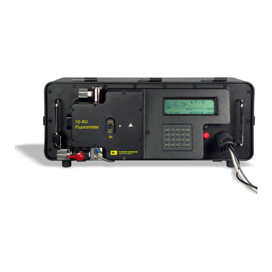
Turner Designs 10-AU Replacement Instructions
Nvram replacement of field fluorometer
Hide thumbs
Also See for 10-AU:
- Quick start operating instructions (13 pages) ,
- Calibration manual (15 pages)
Advertisement
Background
Each fluorometer contains one or two memory chips with embedded batteries. One chip, the NVRAM (non-volatile
data), stores various instrument parameters such as calibration values. The chip's battery will deplete after several
years and need to be replaced.
Battery Failure Notification
If the NVRAM internal battery is low, a warning screen will automatically be displayed when the instrument is turned
on. The screen displays: "WARNING! NEW NVRAM, select <1> to set default." The instrument will still operate, but
once this message appears, every time the fluorometer is turned off it will lose instrument settings and previous
calibration settings.
Temporary Solution
The problem can be mitigated simply by leaving the instrument ON at all times until the NVRAM module can be
changed. If it is turned off, instrument settings will have to be reset and the instrument recalibrated. If this failure
message appears, it is recommended that you write down your parameter settings immediately, in case the
fluorometer is inadvertently turned off.
Note: When the NVRAM fails, data stored in the internal data logger will be saved, as it is not dependent on
the NVRAM.
Note: On rare occasions, you may see "Some NVRAM DATA are corrupted, select <1> to restore default,
select <0> to continue." This may indicate that there is a problem with the NVRAM for storage of instrument
settings. Select <1> and this may temporarily allow you to obtain readings. If readings or software
performance is not normal, contact the manufacturer and we may be able to temporarily mitigate the
problem. If this screen appears, however, you should replace the NVRAM. If it appears again after a new
NVRAM is installed, contact the manufacturer.
IMPORTANT PRECAUTIONS
WARNING!! High voltage up to 1000 volts may be present inside the instrument. Use caution and avoid the
area around the large orange capacitors and lamp transformer (300 V) on the Power PCB (PCB at front of the
instrument, right hand side as you face the front of the unit). Stored voltage will dissipate after a few
minutes.
Note: It is important to follow disassembly and reassembly instructions carefully to avoid damage to internal
components and impairment of instrument function.
Notes on chip handling:
•
Do not touch the metal pins on the chip without discharging static electricity from your hands. To
discharge, touch the metal instrument chassis or handle BEFORE touching the chip.
•
Chip should be stored in a clean, dry place, free of electromagnetic sources.
•
Installation in the wrong orientation will damage the chip and cause a malfunction.
•
Bent or improperly seated pins will cause a malfunction.
NVRAM Installation
1.
UNPLUG THE INSTRUMENT!!!
2.
If the NVRAM has not failed yet and the parameters are still set, go through each screen and write down the
parameters that are currently set (so resetting parameters after installation will be easier).
3.
Remove the fluorometer from the case.
a.
Set the instrument on a clean, dry bench or table, front panel up (facing the ceiling).
b.
Remove the hex-head screws on the perimeter of the front panel.
c.
Grasp the handles on the front panel of the instrument and lift it straight up. It is helpful if someone holds
the case while another person lifts the unit out. Note: Make sure no wiring is caught before final
removal from the case. Be careful not to damage the rubber gasket on the inside perimeter of the
case.
998-0750
Product Instructions:
NVRAM Replacement Instructions
www.turnerdesigns.com
Revision. C
Page 1 of 3
Advertisement
Table of Contents

Related Manuals for Turner Designs 10-AU


Summary of Contents for Turner Designs 10-AU
- Page 1 Product Instructions: NVRAM Replacement Instructions Background Each fluorometer contains one or two memory chips with embedded batteries. One chip, the NVRAM (non-volatile data), stores various instrument parameters such as calibration values. The chip’s battery will deplete after several years and need to be replaced. Battery Failure Notification If the NVRAM internal battery is low, a warning screen will automatically be displayed when the instrument is turned on.
- Page 2 Product Instructions: NVRAM Replacement Instructions Set the instrument carefully on the bench, top side up, with the front of the unit facing toward you. Face the front of the instrument. At your right, toward the back of the instrument is a corner bracket. Locate the rear-most printed circuit board (PCB).
- Page 3 13 in/lbs torque. Plastic faceplate tightening pattern: Reset instrument parameters and calibrate. Turner Designs recommends that the date of installation is documented and affixed to the instrument for future reference. www.turnerdesigns.com 998-0750 Revision.
Need help?
Do you have a question about the 10-AU and is the answer not in the manual?
Questions and answers