
Related Manuals for Turner Designs C3


Summary of Contents for Turner Designs C3
- Page 1 User’s Manual December 5, 2018 P/N: 998-2300 Revision S TURNER DESIGNS 1995 N. 1 Street San Jose, CA 95112 Phone: (408) 749-0994 FAX: (408) 749-0998...
-
Page 2: Table Of Contents
C3 and C6P Submersible Fluorometer Table of Contents Introduction Introduction Important Note Regarding the Use of Fluorescein Optics Inspection and Setup Instrument Checklist Optional Accessories Identification C-Soft Windows™ User Interface Software Installation and PC Requirements 3.1.1 Minimum PC Requirements 3.1.2 Software Installation 3.1.3... - Page 3 C3 and C6P Submersible Fluorometer WASTE ELECTRICAL AND ELECTRONIC EQUIPMENT (WEEE) DIRECTIVE Turner Designs is in the business of designing and selling products that benefit the well-being of our environment. Accordingly, we are concerned with preserving the surroundings wherever our instruments are used and happy to work with customers by complying with the WEEE Directive to reduce the environmental impact resulting from the use of our products.
-
Page 4: Introduction
Chlorophyll and/or Rhodamine sensors or it will produce unreliable results. For C3’s manufactured after 2/15/2011 this interference issue was corrected. If you would like to send your C3 back to Turner Designs to resolve this interference issue, please contact sales@turnerdesigns.com This does not apply to the C6P Submersible Fluorometer. -
Page 5: Inspection And Setup
C3 and C6P Submersible Fluorometer 2. Inspection and Setup 2.1 Instrument Checklist The C3 P/N: 2300-000 and C6P P/N: 2360-000 Submersible Fluorometer package includes: C3 or C6P Submersible Fluorometers Factory-installed temperature sensor Antifouling Copper Tape - C3 only P/N 2300-506. -
Page 6: Optional Accessories
Shade Cap Weight P/N 2300/2360-510 C-ray Towed Deployment Body P/N 2300-750 – available only for the C3. Extender Cables: 10 meters P/N 105-2595 25 meters P/N 105-2596 ... - Page 7 Instructions on the USB Flash Drive for more information. Note: Solid Secondary Standard not available for turbidity. Analog Output Adapter P/N 2300-480 - available only for the C3. See Accessory Instructions on the USB Flash Drive for more information.
-
Page 8: Identification
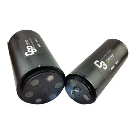
Sensors are marked with numbers located adjacent to the optics on the face of the C3 and C6P Submersible Fluorometers. These numbers correspond to channels 1 through 6 in C-Soft (C3 and C6P software). Note: Channel names can be modified using C-Soft. -
Page 9: C-Soft Windows™ User Interface
3.1.2 Software Installation 1. Exit all Windows programs 2. Insert the USB Flash Drive (also located on the Turner Designs Software / Firmware webpage under Customer Care). 3. Open the C-Soft software folder and double click on the setup icon. -
Page 10: Integration / Interface Adapter Cable Installation
C3 and C6P Submersible Fluorometer 3.1.3 Integration / Interface Adapter Cable Installation 1. Insert the USB Flash Drive and install the Adapter Cable driver (Integration-Interface_Adapter_Drivers.exe) onto your PC. 2. Make sure nothing is plugged into the Adapter Cable’s connectors. 3. Plug the USB connector into a USB port on your computer and wait for hardware to automatically install. -
Page 11: Software Operation
C3 and C6P Submersible Fluorometers to the PC date and time. Each channel (1-6) in the Settings Screen has a location associated with it on the C3 and C6P Submersible Fluorometers that is numerically labeled (1-6), respectively. Channels 4-6 are disabled for the C3. -
Page 12: Current Data And Calibration Screen
C3 and C6P Submersible Fluorometer Settings will automatically be saved after exiting the Settings screen. 3.2.2 Current Data and Calibration Screen The Current Data Screen allows users to view real-time data acquisition, in both tabular and waveform formats as well as conduct calibrations for each channel, and view calibration information. - Page 13 C3 and C6P Submersible Fluorometer Waveform Screen Users can graphically view real-time data for each sensor by clicking the “Display Waveform” box. Channel names and units will be displayed on the Y-axis. Time and date will be displayed on the X-axis.
- Page 14 C3 and C6P Submersible Fluorometer Calibration Screen Users can calibrate sensors in either the direct concentration mode, raw fluorescence mode, or blank subtracted raw fluorescence mode. Direct Concentration Mode Values reported in the Direct Concentration Mode are scaled to a predetermined standard value and blank subtracted.
-
Page 15: Direct Concentration Calibration
C3 and C6P Submersible Fluorometer 3.3 Calibration Procedure 3.3.1 Direct Concentration Calibration Following steps 1-5 below will ensure values are reported as blank subtracted Concentrations in units of choice. See Appendix B for recommended practices. Step 1: Blanking Place the Submersible Fluorometer in a blank solution. -
Page 16: Raw Fluorescence Calibration - Blank Subtracted
C3 and C6P Submersible Fluorometer Data will now be corrected for temperature fluctuations. The temperature compensation coefficients for each fluorophore are listed in the table below. Fluorophore Coefficient Rhodamine 0.026 / °C Exponential in vivo Chlorophyll 0.014 / °C Linear Step 5: Save Calibration ... -
Page 17: Raw Fluorescence Calibration
C3 and C6P Submersible Fluorometer 3.3.3 Raw Fluorescence Calibration In the Current Data screen select the “calibrate” button next to a specific channel. At the bottom of the Calibration Screen select, “Click to use uncalibrated Raw Fluorescence Mode”. Data for that channel will be uncalibrated and reported as “Relative Fluorescence Units”... -
Page 18: Log Setup Screen
3.4 Log Setup Screen The Log Setup screen allows the user to configure a logging session, set the mechanical wiper to its home position, and enable logging. The C3 and C6P Submersible Fluorometer can log over 60,000 lines of data. -
Page 19: Enabling Data Output Ready State
WARNING! As soon as data logging is enabled users will be unable to access C- Soft settings. This should be the last step before the C3 and C6P Submersible Fluorometer is deployed. 3.5 Enabling Data Output Ready State... -
Page 20: Downloading And File Management
Battery Life Calculator available on the Turner Designs website C3 and C6P product pages to calculate a conservative estimation of how many days you can expect to log data. Factors such as battery charge and water temperature will affect logging days. Low battery can result in intermittent logging. - Page 21 C3 and C6P Submersible Fluorometer Note: If you have problems downloading data in C-Soft, you may have limited space in the cache memory on your computer. If you have not done a Disk Cleanup for awhile you may want to try and see if that clears up the problem and allows you to download files.
-
Page 22: Maintenance And Warranty
Do NOT use WD-40, it will destroy the connectors. 4.2 Warranty Terms Turner Designs warrants the C3 and C6P and accessories to be free from defects in materials and workmanship under normal use and service for a period of 12... -
Page 23: Warranty Service
Turner Designs. If the failure is covered under the warranty terms, the instrument will be repaired and returned free of charge, for all customers in the contiguous continental United States. - Page 24 C3 and C6P Submersible Fluorometer 998-2300 Rev. S Page 24...
-
Page 25: A Specifications
C3 and C6P Submersible Fluorometer Appendix A: Specifications Weight in Air 1.64 kg (3.6 lbs) 2.54 kg (5.60 lbs) Length 23 cm (9.1 in.) 27.43 cm (10.80 in.) Diameter 10 cm (3.9 in.) 13.84 cm (5.25 in.) Material Delrin Temperature -2 to 50 °C... -
Page 26: B Recommended Practices
C3 and C6P Submersible Fluorometer Appendix B: Recommended Practices Identification Sensors are labeled adjacent to the optics on the face of the instrument. Each channel is factory set in the C-Soft Windows Software. Note: The channel labels can be modified in the C-Soft software. -
Page 27: C Wiring Guide
C3 and C6P Submersible Fluorometer Appendix C: Wiring Guide The C3 and C6P Submersible Fluorometer outputs digital data in three formats: 1) Digital data that can only be read by the Submersible Fluorometer’s software, 2) Digital data in ASCII format that can be read by larger multi parameter systems such as CTD’s, and 3) Digital data that can be read and converted to analog data by the C-... -
Page 28: D Linear Range, Quenching And Temperature Considerations
C3 and C6P Submersible Fluorometer Appendix D: Linear Range, Quenching and Temperature Considerations The linear range is the concentration range in which the C3 and C6P sensor output is directly proportional to the concentration of the signal. The linear range begins with the smallest detectable concentration and spans to an upper limit (concentration) that is dependent upon the properties of the material, filters used, and path length. -
Page 29: E How To Set Up Hyperterminal For Digital (Ascii) Data Capture
C3 and C6P Submersible Fluorometer Appendix E: How to set up HyperTerminal for Digital (ASCII) Data Capture 1. Ensure C-Soft program is not running in the background. On an MS Windows computer, open the HyperTerminal program StartAll ProgramsAccessoriesCommunications HyperTerminal 2. The Connection Description screen will appear. Name the connection description. - Page 30 C3 and C6P Submersible Fluorometer Most applications will integrate streaming data. Below are instructions on how to save streaming data on a PC. To save data: 1. On the HyperTerminal window toolbar, choose Transfer and then Capture Text. 2. When you click on Capture Text, a window will appear asking you to name and save the .txt file to the location of interest.
-
Page 31: F Integrator Firmware
Appendix F: Integrator Firmware Turner Designs offers Integrator Firmware. This firmware is designed for use by customers that are integrating their C3 and C6P with an external datalogger, CTD or similar system. The Integrator Firmware is different from the standard C3 firmware and has some features that users need to consider before installing: 1. -
Page 32: G Campbell Scientific Cr1000 Datalogger Integration
C3 and C6P Submersible Fluorometer Appendix G: Campbell Scientific CR1000 Datalogger Integration This document assumes you have experience connecting to your CR1000. The procedure of interfacing the C3 and C6P Submersible Fluorometer is described in four sections. Wiring the CR1000 to a PC ... - Page 33 C3 and C6P Submersible Fluorometer Configuring the RS-232 port on the CR1000. 2.1 After the CR1000 is powered and wired to your PC as described in section 1, connect to the CR1000 by clicking on "Connect" in the upper left corner of the PC200W Datalogger Support Software.
- Page 34 C3 and C6P Submersible Fluorometer 2.3 A new window will open titled “Device Configuration Utility 2.06”. Under “Device Type” in the left panel, highlight the CR1000. Select the correct com port, then click “Connect”. 2.4 A warning message will come up asking you to bypass checking for com port conflicts with the local server, click “Bypass”.
- Page 35 3.1 The C3 and C6P uses RS-232 logic levels, therefore, communication between the CR1000 and the C3 and C6P must be on the RS-232 port of the CR1000. The configuration of this port is described in section 2. Connect the 8 pin female underwater connector end of P/N 2200-150 to the C3 and C6P.
- Page 36 C3 and C6P Submersible Fluorometer 4. Loading the CRBasic program onto the CR1000 using PC200W software 4.1 After the CR1000 is powered and wired to your PC as described in section 1, connect to the CR1000 by clicking on "Connect" in the upper left corner of the PC200W Datalogger Support Software.
- Page 37 This timestamp is independent of the timestamp delivered by the C3 and C6P, which is contained in the “RawString” field. The “RawString” field contains the serial string as delivered by the C3 and C6P. “SplitData” fields are the parsed records from the C3 and C6P serial data string.
- Page 38 “SplitData (6)”, “SplitData (7)”, and “SplitData (8)” are fields that would be occupied if the CR1000 were interfaced to a C6P and Turner Designs C6 Multi-Sensor Platform. 4.6 For reference, the serial data string coming from a C3 and C6P into a terminal program is displayed below. 998-2300 Rev.
Need help?
Do you have a question about the C3 and is the answer not in the manual?
Questions and answers