
Related Manuals for Turner Designs Little Dipper 2


Summary of Contents for Turner Designs Little Dipper 2
- Page 1 Little Dipper 2 In-Line Fluorometer December 7, 2018 P/N 998-2821 Version D TURNER DESIGNS 1995 N. 1 Street San Jose, CA 95112 Phone: (408) 749-0994 FAX: (408) 749-0998...
-
Page 2: Table Of Contents
Introduction Inspection and Setup Installation and Operation Installation Tee Installation Operation Little Dipper 2 Calibration Software and Calculations Software Requirements and PC Installation 3.1.1 Minimum PC Requirements 3.1.2 Software and Calibration Cable Installation 3.1.3 PC Software Interface Calibration Calculating Concentration Coefficients... - Page 3 WASTE ELECTRICAL AND ELECTRONIC EQUIPMENT (WEEE) DIRECTIVE Turner Designs is in the business of designing and selling products that benefit the well- being of our environment. Accordingly, we are concerned with preserving the surroundings wherever our instruments are used and happy to work with customers by complying with the WEEE Directive to reduce the environmental impact resulting from the use of our products.
-
Page 4: Introduction
The intensity of the emitted light is proportional to the concentration of the fluorophore in the sample or source water. Turner Designs’ Little Dipper 2 has a low maintenance design that will provide trouble-free performance. -
Page 5: Installation And Operation
2. Installation and Operation 2.1 Installation Turner Designs’ Little Dipper 2 is rated for light industrial environments. Do not install the Little Dipper 2: In direct sunlight or near heat sources - operating temperature 0-50 °C. On vibrating walls or surfaces that affect the flow. -
Page 6: Operation
2.3 Operation Turner Designs’ Little Dipper 2 uses a Light Emitting Diode (LED) at a specific wavelength to excite the fluorophore of interest in samples or source water. Upon excitation, the fluorophore emits a different wavelength of light (fluorescence) that will be detected by the fluorometer’s photodiode. -
Page 7: Software Requirements And Pc Installation
1. Exit all Windows programs 2. Plug the USB connector of Calibration Cable into your computer. 3. Insert the USB Flash Drive (also located on the Turner Designs Customer Care Software / Firmware webpage under Little Dipper 2). 4. If you’re running 64-bit Windows OS, double-click the CP210xVCPInstaller_x64.exe icon to install the correct driver for your operating... - Page 8 Note: If you are not sure which OS your computer is running, please follow the instructions in Appendix C. 5. A screen will appear prompting you to begin the installation process. Click “Next.” 6. Follow the screen prompts to install the driver software. The software will be automatically installed on your computer’s C drive.
-
Page 9: Calibration
3. Begin LD2 software by double-clicking on the LD2 icon. 4. Plug the 12V power supply into a power source and supply power to the calibration cable. Wait for initialization process to complete. 6. Select the Connect to Device button. The Device Connection Status will turn green when connection is established and “Device is now connected”... - Page 10 6) In the same beaker which contains a known volume of your source water, make a solution using your fluorophore of interest that represents a concentration you intend to measure or use Turner Designs prepared calibration standards. Contact Accessory Sales to purchase.
- Page 11 8) Once bubbles have been removed, enter the value for mA at which your calibration solution should be set. Select the Solution Calibration button from the LD2 software screen. The dialog box will then state “Solution Calibration…Please wait”. 9) Once the solution calibration is complete the following screen will appear: 10) You can now install the Little Dipper...
-
Page 12: Calculating Concentration Coefficients
3.3 Calculating Concentration Coefficients You can find the coefficients required for calculating concentrations using the equation: Equation 1: y = mx + c Where: y = the sample concentration, m = the slope of your equation, x = the sensor output in mA, c = the x intercept (offset) when y = 0. -
Page 13: Recommended Measurement Practices
4. Recommended Measurement Practices 4.1 Minimizing Variations in Signal Turner Designs’ Little Dipper 2 has a flat surfaced optical window that might trap air bubbles when positioned vertically. For this reason we recommend: 1) Installing Little Dipper 2 horizontally so that the mounting tee is in a vertical position. - Page 14 Additional information on how to apply these corrections is included in the Turner Designs Application Note: A Practical Guide to Flow Measurements. Table 2: Temperature Coefficients for specific dyes. Changes in the dye concentration are exponential as opposed to linear.
-
Page 15: Maintenance And Warranty
5. Maintenance and Warranty The Little Dipper 2 Fluorometer is designed for light industrial monitoring applications that require continuous measurements. It provides maximum performance and solid state reliability with minimal maintenance. A maintenance check should be made once per month to ensure the optical window is free from any chemical or biological fouling. -
Page 16: Warranty Terms
Plumbing Plug P/N 2820-520 5.3 Warranty Terms Turner Designs warrants the Little Dipper 2 and accessories to be free from defects in materials and workmanship under normal use and service for a period of 12 months from the date of shipment from Turner Designs with the following restrictions: ... -
Page 17: Out Of Warranty Service
Shipment to Turner Designs should be prepaid. Your bill will include return shipment freight charges. Address for Shipment: Turner Designs, Inc. 1995 N. 1 Street San Jose, CA 95112 998-2821 Rev. - Page 18 Equipment Specified as Electrical and Electronic Waste 998-2821 Rev. D Page 18...
-
Page 19: A Fluorometer And Mounting Tee Specifications
Appendix A: Fluorometer and Mounting Tee Specifications Parameter Specification Linearity (over dynamic range) 0.99 r Power Draw 0.88 W @ 12 VDC (1.0 W max.) 8 – 30 VDC Input Voltage 4 – 20 mA Signal Output Light Source Light Emitting Diode Detector Photodiode Warm up time... -
Page 20: B Wiring Guide
Appendix B: Wiring Guide Wire Color Function Connection Supply Voltage PSU – Positive Connection 8 – 30 VDC Supply Ground PSU – Ground Connection Black 0 VDC Signal out to data logger, Multimeter “A” Connection “A”, 4 – 20 mA DC Orange Multimeter “Common”... -
Page 21: C How To Determine Your Version Of Window Os
Appendix C: How to Determine Your Version of Windows OS Is my PC running the 32-bit or 64-bit version of Windows? The terms 32-bit and 64-bit refer to the way a computer's processor (also called a CPU), handles information. The 64-bit version of Windows handles large amounts of random access memory (RAM) more effectively than the 32-bit version. - Page 22 4. With the System applet now open, titled View basic information about your computer, find the System area, located under the large Windows 8 logo. The System type will say either 64-bit Operating System or 32-bit Operating System. Citation: “Is my PC running the 32-bit or 64-bit version of Windows?.” Microsoft Corporation. Viewed online on February 9, 2014 at http://windows.microsoft.com/en-us/windows7/find-out-32-or-64- bit.
-
Page 23: D Tee Modification
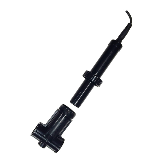
Appendix D: Tee Modification It is possible to modify the tee to add a clean-out plug or other item directly opposite the LD2. This can be done by drilling and tapping the small boss shown in the picture to a 1/2" NPT thread. -
Page 24: E General Information For Calibrating With Ld2 Control Box
Appendix E: General Information for Calibrating with LD2 Control Box The Little Dipper™ 2 may be purchased as a sensor integrated with control boxes from third party vendors, in which case the calibration instructions in section 3.2 cannot be used to calibrate or set a new range for control box wired sensors.
Need help?
Do you have a question about the Little Dipper 2 and is the answer not in the manual?
Questions and answers