Advertisement
ADDENDUM: CLEAN-IN-PLACE SYSTEM
This addendum provides the appropriate general arrangement drawings, installation specifics, and
operating instructions for an E09 TD-4100XD monitor equipped with an integrated clean-in-place (CIP)
system. The functionality and general operational instructions for your monitor remain as described in
the manual, with the exceptions described in this addendum.
In some cases the arrangement and appearance of your CIP-equipped monitor do not match the
graphic images shown in the manual. If you have questions regarding installation, connections, settings,
procedures, or the general appearance of your monitor, contact a service representative at Turner
Designs Hydrocarbon Instruments:
Tel: + 1 559 253 1414, Fax: + 1 559 253 1090, or
Email:
A.1 INSTALLING THE CLEAN-IN-PLACE SYSTEM
The following installation steps include references to Figure A.1.1.
PN 106169
Rev B
service@oilinwatermonitors.com
E09 TD-4100XD Oil In Water Monitor
Clean-In-Place Addendum
1.
Install the valve and pipe combo (1) into
the sample pump discharge port as shown.
Remove the flexible hose if required.
2.
Install the CIP return port (2) as shown.
Make sure that the union half axis is parallel
to the sample pump discharge port axis.
3.
If not yet installed, install the CIP return
port (3) into the 3/4" FNPT tank fitting. This
section shall be vertical to the ground. For
best results, install prior to the CIP main
body.
A-1
Advertisement
Table of Contents

Related Manuals for Turner Designs TD-4100XD E09


Summary of Contents for Turner Designs TD-4100XD E09
- Page 1 ADDENDUM: CLEAN-IN-PLACE SYSTEM This addendum provides the appropriate general arrangement drawings, installation specifics, and operating instructions for an E09 TD-4100XD monitor equipped with an integrated clean-in-place (CIP) system. The functionality and general operational instructions for your monitor remain as described in the manual, with the exceptions described in this addendum.
- Page 2 Addendum: Clean-In-Place System E09 TD-4100XD Install the CIP return port (4) by joining the upper and lower union joints together. Make sure the joints are properly tightened. Install the #10-32 fasteners, attaching the ball valve to the electric actuator. Install the 3/4” NPT CPVC ball valve actuator (6) to the CIP frame as shown.
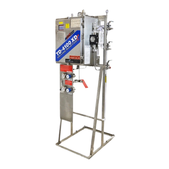
- Page 3 E09 TD-4100XD Addendum: Clean-In-Place System Figure A.1.1 Monitor showing CIP installation points PN 106169 E09 TD-4100XD Oil In Water Monitor Rev B Clean-In-Place Addendum...
-
Page 4: Design Information
Addendum: Clean-In-Place System E09 TD-4100XD The finished CIP system showing the parts requiring assembly. Piece 3 Piece 4 Piece 5 Piece 2 Piece 1 Piece 6 A.1.1 DESIGN INFORMATION • Power to the pump and valve actuators is supplied by the input mains at 115 VAC. •... -
Page 5: Making Piping Connections
E09 TD-4100XD Addendum: Clean-In-Place System A.1.2 MAKING PIPING CONNECTIONS The cleaning solution pump and system is partially plumbed at the factory. Some assembly is required, as detailed in Section A.1 Installing the Clean-In-Place System. To periodically drain the tank, Turner Designs Hydrocarbon Instruments recommends installing a T-valve with hose bib at the CIP outlet shown below and on page 1 of Section A.5 Clean-In-Place General Arrangement... -
Page 6: Making Electrical Connections
The CIP inlet valve actuator shown in a remote installation. The 1/2 in. CPVC ball valve switches inlet from sample stream to CIP system tank. Turner Designs Hydrocarbon instruments strongly recommends installing a vacuum breaker, such as the Plast-O-Matic VBM050V-CP, near the valve outlet. - Page 7 E09 TD-4100XD Addendum: Clean-In-Place System Make connections at terminal blocks as shown. See the key on page 7 of Section A.6 E09 TD-4100XD General Arrangement Drawings for relay assignments and letter and number designations. The fuses immediately above the terminal blocks are 6.3 A fast acting, with the exception of the power (PWR) and CIP pump (I), which use 5 A slow blow fuses.
- Page 8 Addendum: Clean-In-Place System E09 TD-4100XD Bubble trap valve actuator shown with the cover removed. The bubble trap valve and outlet valve must be wired as shown here. Connect to the monitor, using glands and cabling appropriate for your hazardous area requirements.
-
Page 9: Section 9.6.1.1 Online
E09 TD-4100XD Addendum: Clean-In-Place System A.2 OPERATING THE CLEAN-IN-PLACE SYSTEM Prior to operating the clean-in-place system: Remove the cleaning solution tank cover. Fill the tank with cleaning solution to a minimum of 5 U.S. gal [19 L]. The volume of the tank is 10 U.S. - Page 10 Addendum: Clean-In-Place System E09 TD-4100XD Select “1” to set the starting date (must be a current or future date). Select “2” to set the starting time (must be a future time). You must also set the cleaning frequency. Return to the Cell Cleaning screen, and press “4.”...
- Page 11 E09 TD-4100XD Addendum: Clean-In-Place System This image shows the recommended duration settings for steps 1–5 of the cleaning cycle (based on installation specifics stated above). See the next image for “6” More Options. This screen (More Options) shows the remainder of the cleaning cycle steps and their recommended settings.
- Page 12 Addendum: Clean-In-Place System E09 TD-4100XD When the inlet valve has closed, the inlet tubing drains for a recommended duration of 60 seconds. Next the bubble trap valve closes. The recommended duration for this setting is 20 seconds. When all fluid has drained from the sample system, the outlet valve closes.
- Page 13 E09 TD-4100XD Addendum: Clean-In-Place System The bubble trap valve opens and the bubble trap drains back to the tank. The recommended duration for this setting is 45 seconds. Next the bubble trap valve closes. The recommended duration for this step is 20 seconds. The outlet valve returns to process.
-
Page 14: Maintenance
Flush if necessary. Turn off power and uncouple power line to pump. Remove pump from the mounting. Carry out all repair work with extreme cleanliness. Turner Designs Hydrocarbon Instruments recommends you establish a preventive maintenance schedule based on the pump’s service history. This is especially important for prevention of spills or leakage due to pump head failure. - Page 15 Make sure that all suction flows. connections are tight. Pump rattles or excessively Various issues. Contact Turner Designs vibrates. Hydrocarbon Instruments. NOTE: Check all possible problems and causes before disassembling the pump. PN 106169 E09 TD-4100XD Oil In Water Monitor...
- Page 16 E09 TD-4100XD Addendum: Clean-In-Place System A.5 CLEAN-IN-PLACE GENERAL ARRANGEMENT DRAWINGS The CIP general arrangement drawings include multiple system views, monitor installation specifics, and a process and instrumentation diagram. A-16 E09 TD-4100XD Oil In Water Monitor PN 106169 Clean-In-Place Addendum Rev B...
- Page 17 E09 TD-4100XD Addendum: Clean-In-Place System PN 106169 E09 TD-4100XD Oil In Water Monitor A-17 Rev B Clean-In-Place Addendum...
- Page 18 E09 TD-4100XD Addendum: Clean-In-Place System A-18 E09 TD-4100XD Oil In Water Monitor PN 106169 Clean-In-Place Addendum Rev B...
- Page 19 E09 TD-4100XD Addendum: Clean-In-Place System PN 106169 E09 TD-4100XD Oil In Water Monitor A-19 Rev B Clean-In-Place Addendum...
- Page 20 E09 TD-4100XD Addendum: Clean-In-Place System A-20 E09 TD-4100XD Oil In Water Monitor PN 106169 Clean-In-Place Addendum Rev B...
-
Page 21: Chapter 11 General Arrangement
E09 TD-4100XD Addendum: Clean-In-Place System A.6 E09 TD-4100XD GENERAL ARRANGEMENT DRAWINGS This drawing set replaces those shown in Chapter 11 General Arrangement Drawings. PN 106169 E09 TD-4100XD Oil In Water Monitor A-21 Rev B Clean-In-Place Addendum... - Page 22 Addendum: Clean-In-Place System E09 TD-4100XD A-22 E09 TD-4100XD Oil In Water Monitor PN 106169 Clean-In-Place Addendum Rev B...
- Page 23 E09 TD-4100XD Addendum: Clean-In-Place System PN 106169 E09 TD-4100XD Oil In Water Monitor A-23 Rev B Clean-In-Place Addendum...
- Page 24 Addendum: Clean-In-Place System E09 TD-4100XD A-24 E09 TD-4100XD Oil In Water Monitor PN 106169 Clean-In-Place Addendum Rev B...
- Page 25 E09 TD-4100XD Addendum: Clean-In-Place System PN 106169 E09 TD-4100XD Oil In Water Monitor A-25 Rev B Clean-In-Place Addendum...
- Page 26 E09 TD-4100XD Addendum: Clean-In-Place System A-26 E09 TD-4100XD Oil In Water Monitor PN 106169 Clean-In-Place Addendum Rev B...
- Page 27 E09 TD-4100XD Addendum: Clean-In-Place System PN 106169 E09 TD-4100XD Oil In Water Monitor A-27 Rev B Clean-In-Place Addendum...
Need help?
Do you have a question about the TD-4100XD E09 and is the answer not in the manual?
Questions and answers