Table of Contents
Advertisement
Quick Links
ECAT-201x EtherCAT Slave
Modules User Manual
English Ver. 1.2,Dec. 2019
WARRANTY
All products manufactured by ICP DAS are warranted against
defective materials for a period of one year from the date of
delivery to the original purchaser.
WARNING
ICP DAS assumes no liability for damages consequent to the
use of this product. ICP DAS reserves the right to change this
manual at any time without notice. The information furnished
by ICP DAS is believed to be accurate and reliable. However, no
responsibility is assumed by ICP DAS for its use, nor for any
infringements of patents or other rights of third parties
resulting from its use.
COPYRIGHT
Copyright © 2019 by ICP DAS. All rights are reserved.
TRADEMARK
Names are used for identification only and may be registered
trademarks of their respective companies.
CONTACT US
If you have any questions, please feel free to contact us via
email at:
service@icpdas.com, service.icpdas@gmail.com
I/O
S
UPPORT
ECAT-2011H
ECAT-2012H
ECAT-2016N
Advertisement
Table of Contents

Related Manuals for ICP DAS USA ECAT-201x EtherCAT Slave I/O


Summary of Contents for ICP DAS USA ECAT-201x EtherCAT Slave I/O
- Page 1 ECAT-201x EtherCAT Slave Modules User Manual English Ver. 1.2,Dec. 2019 WARRANTY All products manufactured by ICP DAS are warranted against defective materials for a period of one year from the date of delivery to the original purchaser. WARNING ICP DAS assumes no liability for damages consequent to the use of this product.
-
Page 2: Table Of Contents
ECAT-2011H EtherCAT Slave I/O module TABLE OF CONTENTS INTRODUCTION ..............................4 ................................. 5 ACKAGE HARDWARE INFORMATION ..........................6 ................................. 6 PPEARANCE ............................... 8 PECIFICATION 2.2.1 System Specification ............................8 2.2.2 I/O Specification ............................9 ..............................10 SSIGNMENTS EtherCAT Interface ..............................10 Differentail Input(ECAT-2011H/ECAT-2012H) ...................... - Page 3 ECAT-2011H EtherCAT Slave I/O module Index 1C00 Sync Manager Type ..........................31 Index 1C12 RxPDO Assignment ..........................31 Index 1C13 TxPDO Assignment(For ECAT-2011H/2012H) ..................31 Index 1C13 TxPDO Assignment(For ECAT-2016N) ...................... 31 Index 1C32 TxPDO Assignment ..........................32 Index 1C33 SM Input Parameter ..........................33 6000-0 FFFF) ......................
-
Page 4: Introduction
ECAT-2011H EtherCAT Slave I/O module Introduction The ECAT-2000 is equipped with the EtherCAT protocol and installed by daisy chain connection which permits the flexibility in devices installation and reduces infrastructure and operation costs. All the modules can be deployed in the network topologies such as star, line or ring. The ECAT-2011H/2012H is built in 8-ch differential inputs or 16-ch single-ended analog inputs by software selectable,ECAT-2016N is built in 1-ch strain gauge. -
Page 5: Package List
ECAT-2011H EtherCAT Slave I/O module 1.1 Package List The shipping package includes the following items: ECAT-2011H/ Quick Start ECAT-2012H/ ECAT-2016N If any of these items is missing or damaged, please contact your local distributor for more information. Keep the shipping materials and overall package in case you want to NOTE ship the module back in the future. -
Page 6: Hardware Information
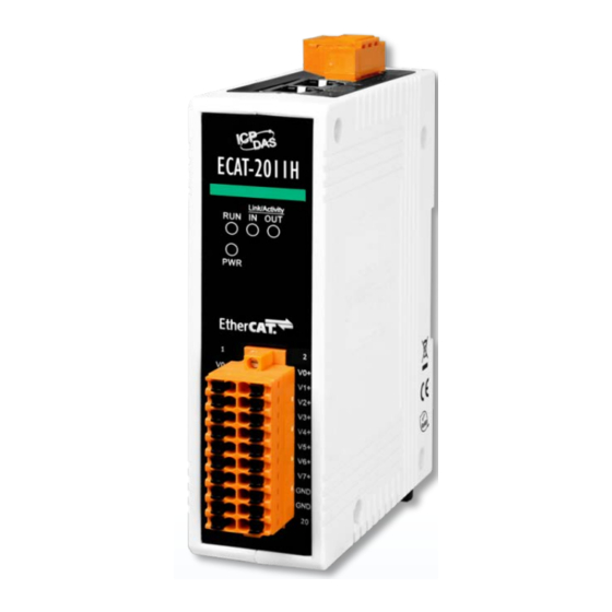
ECAT-2011H EtherCAT Slave I/O module 2. Hardware Information 2.1 Appearance The front panel and top panel of the ECAT module contain the I/O connector, LEDs, Ethernet Port and power connector. Top Panel 1. DC Power Input Connector 2. EtherCAT Interface DC Power Input Connector The “+Vs”... - Page 7 ECAT-2011H EtherCAT Slave I/O module Front Panel 3. Status Indicator 4. PWR LED Indicator 5. I/O Connector Status Indicator Notation Color States Description The device is in state INIT Blinking The device is in state PRE-OPERARIONAL Green Single Flash The device is in state SAFE-OPERARIONAL The device is in state OPERARIONAL No link Link Activity...
-
Page 8: Specification
ECAT-2011H EtherCAT Slave I/O module 2.2 Specification 2.2.1 System Specification Item Specification Communication Ethernet Port 2 x RJ-45, 100 BASE-TX Protocol EtherCAT Distance between Station Max. 100 m (100 BASE-TX) Data Transfer Medium Ethernet/EtherCAT Cable (Min. CAT 5), Shielded LED Indicators L/A IN (Link/Activity IN) L/A OUT (Link/Activity OUT) EMS Protection... -
Page 9: I/O Specification
ECAT-2011H EtherCAT Slave I/O module 2.2.2 I/O Specification Model ECT-2011H ECAT-2012H Analog Input 8/16 Channels 8 Differential or 16 Single-ended (Software Selectable) Wire Connection Voltage, Current Type 0~10 V, ±10 V, ±5 V, ±2.5 V, 0~ 20 mA, ±20 mA, 4~20mA, ±4~20mA Range (Software selectable) 12-bit... -
Page 10: Pin Assignments
ECAT-2011H EtherCAT Slave I/O module 2.3 Pin Assignments EtherCAT Interface Terminal No. Pin Assignment F.G. + Vs Copyright © 2019 ICP DAS CO., Ltd. All Rights Reserved. - 10 -... -
Page 11: Differentail Input(Ecat-2011H/Ecat-2012H)
ECAT-2011H EtherCAT Slave I/O module Differentail Input(ECAT-2011H/ECAT-2012H) Terminal No. Pin Assignment Pin Assignment Terminal No. AGND AGND AGND AGND Single-ended Input(ECAT-2011H/ECAT-2012H) Terminal No. Pin Assignment Pin Assignment Terminal No. AGND AGND AGND AGND Strain Gauge Input (ECAT-2016N) Terminal No. Pin Assignment Pin Assignment Terminal No. -
Page 12: Wiring Connections
ECAT-2011H EtherCAT Slave I/O module 2.4 Wiring Connections The factory default settings of ECAT-2011H/2012H is differentail input. You can refer to Section “AD Input Type Selection” to change the input type. For more details regarding the voltage and current wirings, refer to the table below. NOTE: x = channel unmber Voltage Input (Differential) (Default Settings) -
Page 13: Wiring To The Connector
ECAT-2011H EtherCAT Slave I/O module 2.5 Wiring to the Connector A tip for connection the wire to the connector Use the blade of a flat-head screwdriver to push the wire clamp, then hold until step 2 complete. Insulated Terminals Dimensions ... -
Page 14: Dimensions
ECAT-2011H EtherCAT Slave I/O module 2.6 Dimensions The following diagrams provide the dimensions of the ECAT module and can be used as a reference when defining the specifications for any custom enclosures. All dimensions are in millimeters. Left Side Front Bottom Rear Right Side... -
Page 15: Getting Started
ECAT-2011H EtherCAT Slave I/O module 3. Getting Started This chapter provides a basic overview of how to configure and operate your ECAT-2011H module. 3.1 Connecting the Power and the Host PC Step 1 Connect the IN port on the ECAT-2011H module to the RJ-45 Ethernet port on the Host PC. - Page 16 ECAT-2011H EtherCAT Slave I/O module Step 2 Verify that the LEDs indicators on the ECAT module are illuminated as illustrated below: Once the power is connected, the “PWR” LED should be illuminated in red. Once the Ethernet link is detected, the “IN” LED should be flash in green. ...
-
Page 17: Configuration And Operation
ECAT-2011H EtherCAT Slave I/O module 3.2 Configuration and Operation Before following the steps below, you must first install the EtherCAT Master software (e.g., Beckhoff TwinCAT, refer to http://infosys.beckhoff.com). In this example, we will use Beckhoff TwinCAT 2.x to configuring and operating the ECAT module, and Beckhoff TwinCAT 2.X is the most commonly used EtherCAT Master Software. - Page 18 ECAT-2011H EtherCAT Slave I/O module Step 2 Automatic Scanning The EtherCAT system must be in a safe, de-energized state before the EtherCAT slave I/O module is connected to the EtherCAT network! Switch on the operating power supply, launch the TwinCAT System Manager (Config mode), and scan in the devices, as illustrated in the Figure 3-2.1 below.
- Page 19 ECAT-2011H EtherCAT Slave I/O module Choose the correct network device which is connected to module and click “OK” button Figure 3-2.3 Click “OK” to start scanning Figure 3-2.4 Click “OK” to activate the free run mode Figure 3-2.5 In the left-hand window, ECAT module is now shown in the TwinCAT System Manager. In the right-hand window, the ECAT module is parameterized via “Process Data”...
- Page 20 ECAT-2011H EtherCAT Slave I/O module Figure 3-2.6 Copyright © 2019 ICP DAS CO., Ltd. All Rights Reserved. - 20 -...
- Page 21 ECAT-2011H EtherCAT Slave I/O module The moduel offer two different process data per analog channel for transmission: the analog value Value (16-bit) and status information Status (16-bit) Figure 3-2.7 In the left-hand window, clicking on the “Status” variable in the configuration tree (A), the structure can be opened for linking (B).
- Page 22 ECAT-2011H EtherCAT Slave I/O module Table 3-2-1: Status Word (SW) are defined as: Name Description SW.15 TxPDO Toggle Toggles with each new analog process value, refer Index 0x60n0:10 for details. SW.14 TxPDO State TRUE in the case of an internal error, refer Index 0x60n0:0F for details.
-
Page 23: Self-Test
ECAT-2011H EtherCAT Slave I/O module 3.3 Self-Test This chapter can give you the detail steps about self-test. In this way, user can confirm that ECAT-2011H/2012H well or not. Before the self-test, you must prepare a stable signal source (e.g., dry battery) is available, and than follow the steps described below: ... - Page 24 ECAT-2011H EtherCAT Slave I/O module In the left-hand window, click “AI0” to get and configure state. In the right-hand window, check the voltage vaule in the “Value” item. Figure 3-3.2 Copyright © 2019 ICP DAS CO., Ltd. All Rights Reserved. - 24 -...
-
Page 25: Ad Input Type Selection(Ecat-2011H/2012H)
ECAT-2011H EtherCAT Slave I/O module AD Input Type Selection(ECAT-2011H/2012H) The ECAT-2011H/2012H provides 8-channel of differential inputs or 16-channel single-ended inputs. The factory default settings is differentail input. Refer to the following instructions for details of how to change the Analog Input type. ... - Page 26 ECAT-2011H EtherCAT Slave I/O module Select the “Single-ended” option from the “Enum” drop down options and then click the “OK” Note that all AI channels will be changed to single-ended input. button. Figure 3-3.6 Double-click the “Index 80n0:05 (n = 8 to F, Enable Channel)” to enable AI channel. Here, the AI8 (Index 8080:05) is used as an example.
-
Page 27: Ad Range Selection
ECAT-2011H EtherCAT Slave I/O module AD Range Selection The ECAT-2011H provides Analog Input voltage range of ±10 V, ±5 V, ±2.5 V, 0 ~ +10 V and Analog Input currnet range of ±20 mA, 0 ~ +20 mA, +4 ~ +20 mA. The factory default a setting is ±... -
Page 28: Object Description And Parameterization
ECAT-2011H EtherCAT Slave I/O module 4. Object Description and Parameterization The CoE interface is used for parameter management of EtherCAT devices. The display matches that of the CoE objects from the XML device description (ESI file). Once the ECAT connected to EtherCAT Master, you can configure the parameters via “CoE –... -
Page 29: Standard Object
ECAT-2011H EtherCAT Slave I/O module The following section first describes the standard objects required, followed by a complete overview of profile specific objects. 4.1 Standard Object(0x1000-0x1FFF) Index 1000 Device Type Index Name Meaning Data type Flags Default 1000:00 Device type Device type of the EtherCAT slave: the UINT32 0x00000192 (402dec) -
Page 30: Index 1018 Identity
ECAT-2011H EtherCAT Slave I/O module Index 1018 Identity Index Name Meaning Data type Flags Default 1018:00 Identity Information for identifying the slave INT8 0x04(4dec) 0x00494350 1018:01 Vendor ID Vendor ID of the EtherCAT slave UINT32 (4801360dec) 1018:02 Product code Product code of the EtherCAT slave UINT32 Depend on device 1018:03... -
Page 31: Index 1C00 Sync Manager Type
ECAT-2011H EtherCAT Slave I/O module Index 1C00 Sync Manager Type Index Name Meaning Data type Flags Default 1C00:00 Sync manager type Using the sync managers UINT8 0x04(4dec) 1C00:01 SubIndex 001 Sync-Manager Channel 1:Mailbox write UINT8 0x01(1dec) 1C00:02 SubIndex 002 Sync-Manager Channel 2:Mailbox read UINT8 0x02(2dec) 1C00:03... -
Page 32: Index 1C32 Txpdo Assignment
ECAT-2011H EtherCAT Slave I/O module Index 1C32 TxPDO Assignment Index Name Meaning Data type Flags Default SM output UINT8 0x20(32dec) 1C32:00 Synchronization parameters for the outputs parameter Current synchronization type: Bit0 = 0: Free Run Synchronization 0x0000(0dec) Bit1 = 1:Synchron with SM 2 Event UINT16 1C32:01 type... -
Page 33: Index 1C33 Sm Input Parameter
ECAT-2011H EtherCAT Slave I/O module Index 1C33 SM Input Parameter Index Name Meaning Data type Flags Default 1C33:00 SM input parameter Synchronization parameters for the inputs UINT8 0x20(32dec) Current synchronization type: 0x0000(0dec) Bit0 = 0: Free Run Synchronization (Only support 1C33:01 Bit1 = 1:Synchron with SM 2 Event UINT16... -
Page 34: Index 60N0 Ai Inputs (For 0 ≤ N ≤ F)
ECAT-2011H EtherCAT Slave I/O module Index 60n0 AI Inputs (for 0 ≤ n ≤ F) Index Name Meaning Data type Flags Default 60n0:00 AI Inputs Maximum subindex UINT16 RO P 0x11(17dec) 60n0:01 Underrange Value below measuring range BOOLEAN RO P FALSE(0dec) 60n0:02 Overrange... -
Page 35: Index 80N0 Ai Settings (For 0 ≤ N ≤ F ,For Ecat-2011H/2012H)
ECAT-2011H EtherCAT Slave I/O module Index 80n0 AI Settings (for 0 ≤ n ≤ F ,for ECAT-2011H/2012H) Index Name Meaning Data type Flags Default 80n0:00 AI Settings Maximum subindex UINT8 0x1A(26dec) 80n0:01 Enalbe user scale User scale is active BOOLEAN FALSE(0dec) Change the method of representation of the measured value. - Page 36 ECAT-2011H EtherCAT Slave I/O module Index Name Meaning Data type Flags Default 80n0:11 User scale offset User scaling offset INT16 0x00(0dec) 80n0:12 User scale gain User scaling gain. INT32 0x0x0001000 The value 1 corresponds to 65535 dec (65535dec) (0x00010000) and is limited to ±0x7FFFF.
-
Page 37: Index 80N0 Ai Settings (For 0 ≤ N ≤ F ,For Ecat-2016N)
ECAT-2011H EtherCAT Slave I/O module Index 80n0 AI Settings (for 0 ≤ n ≤ F ,for ECAT-2016N) Index Name Meaning Data type Flags Default 80n0:00 AI Settings Maximum subindex UINT8 0x1A(26dec) 80n0:01 Enalbe user scale User scale is active BOOLEAN FALSE(0dec) Change the method of representation of the measured value. - Page 38 ECAT-2011H EtherCAT Slave I/O module Index Name Meaning Data type Flags Default 80n0:11 User scale offset User scaling offset INT16 0x00(0dec) 80n0:12 User scale gain User scaling gain. INT32 0x0x0001000 The value 1 corresponds to 65535 dec (65535dec) (0x00010000) and is limited to ±0x7FFFF.
- Page 39 ECAT-2011H EtherCAT Slave I/O module Table 4-2-1: Signed Integer representation as follows: The negative output value is represented in two’s complement (negated + 1). Maximum representation range for 16 bits = -32768 to +32767dec Input signal Value 4-20 Decimal Hexadecimal ±10 ±5...
- Page 40 ECAT-2011H EtherCAT Slave I/O module Table 4-2-2: Unsigned Integer representation as follows: The output value is represented with 15-bit resolution without sign, therefore polarity detection is no longer possible. Maximum representation range for 16 bits = 0 to +32767dec Input signal Value 4-20...
- Page 41 ECAT-2011H EtherCAT Slave I/O module Table 4-2-3: Absolute value with MSB as sign - representation as follows: The output value is displayed in magnitude-sign format: MSB=1 (highest bit) in the case of negative values. Maximum representation range for 16 bits = -32767 to +32767dec Input signal Value 4-20...
-
Page 42: Index 80Ne Ai Internal Data (For 0<=N<=F)
ECAT-2011H EtherCAT Slave I/O module Index 80nE AI Internal Data (for 0<=n<=F) Index Name Meaning Data type Flags Default 80nE:00 AI Internal data Maximum subindex UINT8 0x1(1dec) 80nE:01 ADC raw value ADC raw value UINT16 0x0008(8dec) Index 80nF AI Vendor Data (for 0<=n<=F) Index Name Meaning... -
Page 43: Appendix: Revision History
ECAT-2011H EtherCAT Slave I/O module Appendix: Revision History This chapter provides revision history information to this document. The table below shows the revision history. Revision Date Description Oct. 08 2018 Initial issue Dec. 2018 Add the unit conversion table about Signed Integer, Unsigned Integer and Most Significant Bit (MSB).
Need help?
Do you have a question about the ECAT-201x EtherCAT Slave I/O and is the answer not in the manual?
Questions and answers