Table of Contents
Advertisement
Quick Links
Advertisement
Table of Contents

Related Manuals for ICP DAS USA ET-87P2


Summary of Contents for ICP DAS USA ET-87P2
- Page 1 ET-87P2/4/8 User Manual Version 1.0.1, November 2011 ET-87P2 ET-87P4 ET-87P8 Written by Hans Chen Edited by Anna Huang ET-87P2/4/8 Series User Manual, version 1.0.1 Page: 1 Copyright © 2011 ICP DAS Co., Ltd. All Rights Reserved. E-mail: service@icpdas.com...
- Page 2 If you have any problem, please feel free to contact us. You can count on us for quick response. Email: service@icpdas.com ET-87P2/4/8 Series User Manual, version 1.0.1 Page: 2 Copyright © 2011 ICP DAS Co., Ltd. All Rights Reserved. E-mail: service@icpdas.com...
-
Page 3: Table Of Contents
2.5.2. Using Man-Machine Interface to Assign an IP Address ......40 2.6. Creating Virtual COM Ports Using VxComm Utility ....... 44 2.7. Establishing PC to ET-87P2/4/8 Communications ........ 49 3. I/O Configuration ............... 52 3.1. Creating the I/O Configuration .............. 53 3.2. - Page 4 3.3.2. Restoring/Importing the I/O Configuration ..........60 3.3.3. Restoring/Importing the I/O Configuration and Writing to 87P4/8 .... 63 3.4. Saving the I/O Configuration File without ET-87P2/4/8 Online ..... 65 4. Tools and SDKs ..............68 4.1. Tools ...................... 69 4.1.1. DCON Utility .................... 70 4.1.2.
-
Page 5: Introduction
Users can easily simplify the cabling and save installation space with the feature. ET-87P2/4/8 is designed to be used in harsh and noisy environment, so the hardware is manufactured with wide power input range (10~30 V ), isolated power input and can operate under wide temperature (-25 °C ~ +75 °C). -
Page 6: Features
ET-87Pn. When the ET-87Pn is power on or plugged in, the ET-87Pn will automatically checks and restores these configurations to each I-87K I/O modules on it. ET-87P2/4/8 Series User Manual, version 1.0.1 Page: 6 Copyright © 2011 ICP DAS Co., Ltd. All Rights Reserved. E-mail: service@icpdas.com... - Page 7 The push buttons and LED display design makes it easy for maintenance. There is no PC and Notebook needed. ET-87P2/4/8 Series User Manual, version 1.0.1 Page: 7 Copyright © 2011 ICP DAS Co., Ltd. All Rights Reserved. E-mail: service@icpdas.com...
- Page 8 I/O system. With its user-friendly interface, users can quickly and easily build the data logger software without any programming skill. ET-87P2/4/8 Series User Manual, version 1.0.1 Page: 8 Copyright © 2011 ICP DAS Co., Ltd. All Rights Reserved. E-mail: service@icpdas.com...
- Page 9 ET-87Pn slaves simultaneously. If the number of ET-87Pn salve is more than 10, it is recommended to increase a switch. ET-87P2/4/8 Series User Manual, version 1.0.1 Page: 9 Copyright © 2011 ICP DAS Co., Ltd. All Rights Reserved. E-mail: service@icpdas.com...
- Page 10 Safe Vale. ● Wide Range Power Input (10 ~ 30 V ● Wide Range Operating Temperature (-25 ~ +75 °C) ET-87P2/4/8 Series User Manual, version 1.0.1 Page: 10 Copyright © 2011 ICP DAS Co., Ltd. All Rights Reserved. E-mail: service@icpdas.com...
- Page 11 Auto- Communication parameter Setup Auto-Configuration High Profile Low Profile 81.08 66.7 102.14 87.46 Please refer to web page : http://www.icpdas.com/products/PAC/i-8000/8000_IO_modules.htm ET-87P2/4/8 Series User Manual, version 1.0.1 Page: 11 Copyright © 2011 ICP DAS Co., Ltd. All Rights Reserved. E-mail: service@icpdas.com...
-
Page 12: Specification
-10 ˚C ~ +75 ˚C Operating Temperature -30 ˚C ~ +75 ˚C Storage Temperature Humidity 5 ~ 95 %, non- condensing ET-87P2/4/8 Series User Manual, version 1.0.1 Page: 12 Copyright © 2011 ICP DAS Co., Ltd. All Rights Reserved. E-mail: service@icpdas.com... - Page 13 Redundant Input Reverse polarity protection Isolation 3000 V Frame Ground Consumption 2.4 W Power Board Driving 10 ~ 30 V (non-regulated) ET-87P2/4/8 Series User Manual, version 1.0.1 Page: 13 Copyright © 2011 ICP DAS Co., Ltd. All Rights Reserved. E-mail: service@icpdas.com...
-
Page 14: Overview
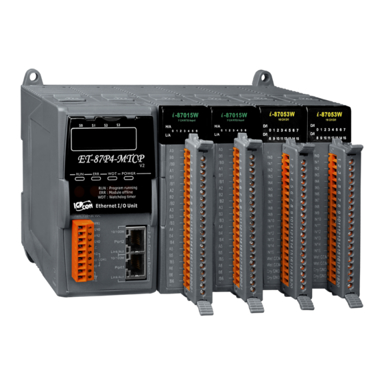
1.3. Overview Here is a brief description of the components. ET-87P2 ET-87P4 ET-87P2/4/8 Series User Manual, version 1.0.1 Page: 14 Copyright © 2011 ICP DAS Co., Ltd. All Rights Reserved. E-mail: service@icpdas.com... - Page 15 ET-87P2/4/8. For more information about the operating mode, please refer to “2.3. Configuring the Boot Mode” ● Man-Machine Interface The ET-87P2/4/8 Man-Machine interface includes LED displays, status indicators and function buttons. ET-87P2/4/8 Series User Manual, version 1.0.1 Page: 15...
- Page 16 The SET button shows the parameter values in the LED display. If in configuration mode, the SET button will move the set-point. ET-87P2/4/8 Series User Manual, version 1.0.1 Page: 16 Copyright © 2011 ICP DAS Co., Ltd. All Rights Reserved. E-mail: service@icpdas.com...
- Page 17 Frame Ground ● 2 LAN Ports The ET-87P2/4/8 has two Ethernet ports. One port is used to interface with a network, and other is used as a router to set up a daisy chain topology. ET-87P2/4/8 Series User Manual, version 1.0.1 Page: 17 Copyright ©...
- Page 18 ● 2/4/8 I/O Expansion Slots The ET-87P2/4/8 has 4/8 I/O expansion slots to expand the functions of the ET-87P2/4/8, each I/O expansion slots has different numbers for use with the I/O modules. The ET-87P2/4/8 has 2/4/8 I/O expansion slots that are numbered 0-1/0-3/0-7.
-
Page 19: Dimension
Remember to leave room for potential expansion if you are using other components in your system. The height dimension is the same for all ET-87P2/4/8. The width depending on your choose of I/O expansion slots. All dimensions are in millimeters. - Page 20 ET-87P4 ET-87P2/4/8 Series User Manual, version 1.0.1 Page: 20 Copyright © 2011 ICP DAS Co., Ltd. All Rights Reserved. E-mail: service@icpdas.com...
- Page 21 ET-87P8 ET-87P2/4/8 Series User Manual, version 1.0.1 Page: 21 Copyright © 2011 ICP DAS Co., Ltd. All Rights Reserved. E-mail: service@icpdas.com...
-
Page 22: Companion Cd
This package comes with a CD that provides drivers, software utility, all of the required documentations…, etc. All of them are listed below. CD:\NAPDOS 87pn_io_unit ET-87Pn Document Firmware OS_Image PC_Tool DCON_Utility MiniOS7_Utility VxComm_Utiltiy ET-87P2/4/8 Series User Manual, version 1.0.1 Page: 22 Copyright © 2011 ICP DAS Co., Ltd. All Rights Reserved. E-mail: service@icpdas.com... -
Page 23: Getting Started
2. Getting Started If you are a new user, begin with this chapter, it includes a guided tour that provides a basic overview of installing, configuring and using the ET-87P2/4/8. Before beginning any installation, please check the package contents. If any items are damaged or missing, please contact us. -
Page 24: Mounting The Hardware
For more information about the hardware dimensions, please refer to “1.3. Dimension” Step 1: Mounting the ET-87P2/4/8 The ET-87P2/4/8 can be mounted with the bottom of the chassis on the standard 35 mm DIN rail, or it can be surface mounted. Make sure the following installation requirements are met. - Page 25 Step 2: Connecting to power supply The ET-87P2/4/8 has redundant power, you can be powered by +10 ~ +30 VDC via one of power supplies. The following diagram shows the terminal connections located on the power supply of the ET-87P2/4/8.
- Page 26 Step 3: Connecting to network and PC The ET-87P2/4/8 is equipped with RJ-45 Ethernet ports for connection to network and Tips & Warnings In a daisy chain connection, each master can connect up to 10 ET-87Pn slaves simultaneously. If the number of ET-87Pn salve is more than 10, it is recommended to increase a switch.
-
Page 27: Inserting The I/O Modules
2.2. Inserting the I/O Modules The ET-87P2/4/8 has 4/8 I/O expansion slots to expand the functions of the ET-87P2/4/8, allowing it to communicate with external I/O modules, and before choosing the right I/O modules, you first need to know the I/O expansion capacities in order to choose the best expansion module for achieving maximal efficiency. - Page 28 Step 1: Align circuit card with slot and press firmly to seat module into connector Step 2: Pull top and bottom locking tabs toward module face. Click indicates lock is engaged. ET-87P2/4/8 Series User Manual, version 1.0.1 Page: 28 Copyright © 2011 ICP DAS Co., Ltd. All Rights Reserved. E-mail: service@icpdas.com...
- Page 29 Step 3: Wiring the I/O modules to the monitored Inputs and Voltages ET-87P2/4/8 Series User Manual, version 1.0.1 Page: 29 Copyright © 2011 ICP DAS Co., Ltd. All Rights Reserved. E-mail: service@icpdas.com...
-
Page 30: Configuring The Boot Mode
2.3. Configuring the Boot Mode The ET-87P2/4/8 can be configured in three modes of operation to provide has three operating modes that can be determined through a DIP switch. Switch Position Mode of Operation Description Init Init Mode OS cannot execute autoexec.bat... -
Page 31: Init Mode
Init mode is used to update the OS image and upgrade the firmware. If dip switch is set as Init mode and reset the power, the ET-87P2/4/8 cannot boot up with autoexec.bat and will enter OS operation mode, in this case there is no program... -
Page 32: Running Mode
5-digits 7-SEG LEDs will show the message according to the running program, but if during this time there is another program running on ET-87P2/4/8, the 5-digits 7-SEG LEDs isn’t managed with this program, it will stop motion at the present state. -
Page 33: Installing Tools And Utilities
RS-232 ports can now communicate over Ethernet or Internet TCP/IP ports The VxComm Utility can be obtained from companion CD or our FTP site: CD:\Napdos\driver\vxcomm_driver\ ftp://ftp.icpdas.com/pub/cd/8000cd/napdos/driver/vxcomm_driver/ ET-87P2/4/8 Series User Manual, version 1.0.1 Page: 33 Copyright © 2011 ICP DAS Co., Ltd. All Rights Reserved. E-mail: service@icpdas.com... - Page 34 I/O expansion modules. The DCON Utility can be obtained from companion CD or our FTP site: CD:\Napdos\driver\dcon_utility\ ftp://ftp.icpdas.com/pub/cd/8000cd/napdos/driver/dcon_utility/ ET-87P2/4/8 Series User Manual, version 1.0.1 Page: 34 Copyright © 2011 ICP DAS Co., Ltd. All Rights Reserved. E-mail: service@icpdas.com...
-
Page 35: Assigning A New Ip Address
192.168.255.1 Subnet Mask 255.255.0.0 Gateway 192.168.0.1 The IP settings of the ET-87P2/4/8 can be set in one of three ways. Using MiniOS7 Utility Use ET-87P2/4/8 Web Site Use Man-Machine Interface ET-87P2/4/8 Series User Manual, version 1.0.1 Page: 35... -
Page 36: Assign A New Ip Address Using Minios7 Utility
2.5.1. Assign a New IP Address Using MiniOS7 Utility MiniOS7 Utility is an easy-to-use network configuration Utility. You can configure the ET-87P2/4/8 to connect to a LAN by using it. Step 1: Reboot the ET-87P2/4/8 at Run mode Make sure the switch is set to the “Run”... - Page 37 Choose default value “192.168.255.1” for fields in the list, and then choose IP setting from the toolbar. 1. Choose the field “192.168.255.1” ET-87P2/4/8 Series User Manual, version 1.0.1 Page: 37 Copyright © 2011 ICP DAS Co., Ltd. All Rights Reserved. E-mail: service@icpdas.com...
- Page 38 After completing the settings, the Confirm dialog box will appear, and then choose the Yes button to exit the procedure. ET-87P2/4/8 Series User Manual, version 1.0.1 Page: 38 Copyright © 2011 ICP DAS Co., Ltd. All Rights Reserved. E-mail: service@icpdas.com...
- Page 39 After completing the settings, you can reboot the module and then using MiniOS7 to search module again for making sure that your IP settings are correct. ET-87P2/4/8 Series User Manual, version 1.0.1 Page: 39 Copyright © 2011 ICP DAS Co., Ltd. All Rights Reserved. E-mail: service@icpdas.com...
-
Page 40: Using Man-Machine Interface To Assign An Ip Address
The ET-87P2/4/8 Man-Machine Interface consists of an operator panel. You can configure an IP address without any computer. Step 1: Reboot the ET-87P2/4/8 at Run mode Make sure the switch is set to the “Run” position before you boot up the ET-87P2/4/8. ET-87P2/4/8 Series User Manual, version 1.0.1 Page: 40... - Page 41 UP: Increase the value DOWN: Reduce the value SET: Save the configuration and skip to the next point ET-87P2/4/8 Series User Manual, version 1.0.1 Page: 41 Copyright © 2011 ICP DAS Co., Ltd. All Rights Reserved. E-mail: service@icpdas.com...
- Page 42 UP: Increase the value DOWN: Reduce the value SET: Save the configuration and skip to the next point ET-87P2/4/8 Series User Manual, version 1.0.1 Page: 42 Copyright © 2011 ICP DAS Co., Ltd. All Rights Reserved. E-mail: service@icpdas.com...
- Page 43 If you don’t have to check the IP settings, you just push the SET button, the 5 digital LEDs will show the IP settings twice. ET-87P2/4/8 Series User Manual, version 1.0.1 Page: 43 Copyright © 2011 ICP DAS Co., Ltd. All Rights Reserved. E-mail: service@icpdas.com...
-
Page 44: Creating Virtual Com Ports Using Vxcomm Utility
2.6. Creating Virtual COM Ports Using VxComm Utility The ET-87P2/4/8 is equipped with two Ethernet ports. You can be sent and received RS-232 series data across the Ethernet ports by creating virtual COM ports.. Step 1: Run the VxComm Utility Double-click the VxComm Utility shortcut on your desktop. - Page 45 Step 2: Press “Search Servers” button from the toolbar After pressing Search Servers from toolbar, that will search all of your network modules. Press the “Search Servers” ET-87P2/4/8 Series User Manual, version 1.0.1 Page: 45 Copyright © 2011 ICP DAS Co., Ltd. All Rights Reserved. E-mail: service@icpdas.com...
- Page 46 Choose the IP Address field you specified in the list, and then press Add Server(s) from the toolbar. 1. Choose the IP Address field you specified ET-87P2/4/8 Series User Manual, version 1.0.1 Page: 46 Copyright © 2011 ICP DAS Co., Ltd. All Rights Reserved. E-mail: service@icpdas.com...
- Page 47 Check the “Maps virtual COM ports to “Port I/O” on servers” iii. Click OK button 1. Choose the COM Port name you wish to use ET-87P2/4/8 Series User Manual, version 1.0.1 Page: 47 Copyright © 2011 ICP DAS Co., Ltd. All Rights Reserved. E-mail: service@icpdas.com...
- Page 48 Step 5: Press “Exit” button form the toolbar and then restart the driver After completing the settings, press Exit button to restart the driver for effecting the settings. ET-87P2/4/8 Series User Manual, version 1.0.1 Page: 48 Copyright © 2011 ICP DAS Co., Ltd. All Rights Reserved. E-mail: service@icpdas.com...
-
Page 49: Establishing Pc To Et-87P2/4/8 Communications
2.7. Establishing PC to ET-87P2/4/8 Communications DCON Utility is an easy-to-use I/O configuration Utility. Before configuring any I/O settings, you need first establish a connection between ET-87P2/4/8 and PC. Step 1: Run the DCON Utility Double-click the DCON Utility shortcut on your desktop. - Page 50 As name you created by VxComm Utility Baud Rate Option Any baud rate options you can choose Checksum Option Disable Parity Option None (N,8,1) ET-87P2/4/8 Series User Manual, version 1.0.1 Page: 50 Copyright © 2011 ICP DAS Co., Ltd. All Rights Reserved. E-mail: service@icpdas.com...
- Page 51 Step 4: The connection has been successfully completed After the search has been done, the name of the ET-87P2/4/8 will display in the list. The address of the ET-87P2/4/8 is always the 1. ET-87P2/4/8 Series User Manual, version 1.0.1 Page: 51 Copyright ©...
-
Page 52: I/O Configuration
3. I/O Configuration The ET-87P2/4/8 automatically detects any installed I/O modules at power up. Before communicating with the I/O module, we must first create the I/O configuration to ET-87P2/4/8 for initiating the I/O modules. For more information on how to create the I/O configuration, please refer to “3.1. -
Page 53: Creating The I/O Configuration
Step 2: Click the name of the ET-87P2/4/8 from the list and then choose the “Configure Module” After clicking the name of the ET-87P2/4/8 from the list, a dialog will appear, then choose the “Configure Module” button ET-87P2/4/8 Series User Manual, version 1.0.1 Page: 53 Copyright ©... - Page 54 After choosing the Set As Scanned button, the found I/O module name will appear in the first column of each item. ET-87P2/4/8 Series User Manual, version 1.0.1 Page: 54 Copyright © 2011 ICP DAS Co., Ltd. All Rights Reserved. E-mail: service@icpdas.com...
- Page 55 After choosing the Set As Scanned button, then you can click the configuration button of each found I/O module to configure the I/O module. ET-87P2/4/8 Series User Manual, version 1.0.1 Page: 55 Copyright © 2011 ICP DAS Co., Ltd. All Rights Reserved. E-mail: service@icpdas.com...
- Page 56 Warning dialog will appear, and then click Yes button to continue effecting the settings, The I/O configuration will be written to ET-87P2/4/8. ET-87P2/4/8 Series User Manual, version 1.0.1 Page: 56 Copyright © 2011 ICP DAS Co., Ltd. All Rights Reserved. E-mail: service@icpdas.com...
-
Page 57: Checking The I/O Configuration
Step 2: Choose the name of the ET-87P2/4/8 from the list and then choose the “Check Module Status” After clicking the name of the ET-87P2/4/8 from the list, a dialog will appear, then choose the “Check Module Status” button ET-87P2/4/8 Series User Manual, version 1.0.1 Page: 57 Copyright ©... - Page 58 After choosing Check Module Status button, a dialog will appear, and display all configured I/O modules, and then choose the status button one of the I/O configuration that you want to monitor. ET-87P2/4/8 Series User Manual, version 1.0.1 Page: 58 Copyright © 2011 ICP DAS Co., Ltd. All Rights Reserved. E-mail: service@icpdas.com...
-
Page 59: Backing Up/Restore The I/O Configuration
ET-87P2/4/8, or import another ET-87P2/4/8. 3.3.1. Backing up the I/O Configuration After configuring and writing to ET-87P2/4/8, you can saving the configuration. This function can be useful if you need to make backups of ET-87P2/4/8. ET-87P2/4/8 Series User Manual, version 1.0.1 Page: 59... -
Page 60: Restoring/Importing The I/O Configuration
3.3.2. Restoring/Importing the I/O Configuration Once you have saved a configuration file of the ET-87P2/4/8, you can use this option to restore the ET-87P2/4/8, or import to another ET-87P2/4/8. Step 1: Choose Load Configuration button After choosing the Load Configuration button, the Open dialog will appear. - Page 61 After choosing the Load Configuration button, the Open will appear, and then select the I/O configuration file you wish to use. ET-87P2/4/8 Series User Manual, version 1.0.1 Page: 61 Copyright © 2011 ICP DAS Co., Ltd. All Rights Reserved. E-mail: service@icpdas.com...
- Page 62 Step 3: The configuration parameters have been loaded successfully ET-87P2/4/8 Series User Manual, version 1.0.1 Page: 62 Copyright © 2011 ICP DAS Co., Ltd. All Rights Reserved. E-mail: service@icpdas.com...
-
Page 63: Restoring/Importing The I/O Configuration And Writing To 87P4/8
Step 1: Choose Load Configuration And Write To 87PX button After choosing the Load Configuration And Write to 87PX button, the Open dialog will appear. ET-87P2/4/8 Series User Manual, version 1.0.1 Page: 63 Copyright © 2011 ICP DAS Co., Ltd. All Rights Reserved. E-mail: service@icpdas.com... - Page 64 After choosing the Load Configuration button, the Open will appear, and then select the I/O configuration file you wish to use. ET-87P2/4/8 Series User Manual, version 1.0.1 Page: 64 Copyright © 2011 ICP DAS Co., Ltd. All Rights Reserved. E-mail: service@icpdas.com...
-
Page 65: Saving The I/O Configuration File Without Et-87P2/4/8 Online
Online DCON Utility can save the ET-87P2/4/8 I/O configuration file without connect ET-87P2/4/8 and any I/O modules. You may use this function to create the configuration file. It is convenient for remote support and system backup. Step 1: Press “... - Page 66 Step 3: Configure the I/O module Select and configure the I/O module, then save the settings as another file name. ET-87P2/4/8 Series User Manual, version 1.0.1 Page: 66 Copyright © 2011 ICP DAS Co., Ltd. All Rights Reserved. E-mail: service@icpdas.com...
- Page 67 Step 4: Choose “Save Configuration” button After choosing Save Configuration button, the Save As… dialog will appear, and the type the file name. ET-87P2/4/8 Series User Manual, version 1.0.1 Page: 67 Copyright © 2011 ICP DAS Co., Ltd. All Rights Reserved. E-mail: service@icpdas.com...
-
Page 68: Tools And Sdks
87pn_io_unit ET-87Pn PC_Tool DCON_Utility MiniOS7_Utility VxComm_Utility Driver DCON_ActiveX DCON_ActiveX_New DCON_DasyLab DCON_DDE DCON_DLL DCON_DLL_New DCON_GWBasic DCON_InduSoft DCON_LabVIEW DCON_Linux DCON_Utility EZ_Data_Logger VxComm_Driver ET-87P2/4/8 Series User Manual, version 1.0.1 Page: 68 Copyright © 2011 ICP DAS Co., Ltd. All Rights Reserved. E-mail: service@icpdas.com... -
Page 69: Tools
4.1. Tools There are three main tools for managing the ET-87P2/4/8. All of tools are list below. CD:\NAPDOS 87pn_io_unit ET-87Pn PC_Tool DCON_Utility MiniOS7_Utility VxComm_Utiltiy The following lists summarize the functions of these tools. DCON Utility Configure I/O modules (Please refer to 3. I/O Configuration) MiniOS7 Utility ... -
Page 70: Dcon Utility
For more detailed information on DCON Utility applications, please refer to “3. I/O configuration” For more details, please refer to DCON Utility web site: http://www.icpdas.com/products/dcon/introduction.htm ET-87P2/4/8 Series User Manual, version 1.0.1 Page: 70 Copyright © 2011 ICP DAS Co., Ltd. All Rights Reserved. E-mail: service@icpdas.com... -
Page 71: Minios7 Utility
“2.5.1. Using MiniOS7 Utility to assign a new IP” For more detailed information on how to using MiniOS7 Utility to update the ET-87P2/4/8, please refer to “5. ET-87P2/4/8 Updates” ET-87P2/4/8 Series User Manual, version 1.0.1 Page: 71... -
Page 72: Vxcomm Utility
Ethernet port of the ET-87P2/4/8. Commands and data sending to the virtual COM ports will be redirected to the ET-87P2/4/8’s Ethernet ports. And the received data from ET-87P2/4/8's COM ports will also be redirected to PC's virtual COM ports. For more detailed information on how to create virtual COM ports, please refer to “2.4. -
Page 73: Sdks
DCON_LabVIEW DCON_Linux DCON_Utility EZ_Data_Logger VxComm_Driver For details of the function and example applications of the ET-87P2/4/8, please refer http://www.icpdas.com/products/dcon/introduction.htm http://ftp.icpdas.com/pub/cd/8000cd/napdos/driver/ ET-87P2/4/8 Series User Manual, version 1.0.1 Page: 73 Copyright © 2011 ICP DAS Co., Ltd. All Rights Reserved. E-mail: service@icpdas.com... -
Page 74: 87P2/4/8 Updates
5. ET-87P2/4/8 Updates The ET-87P2/4/8 updates can be divided into two classes: OS updates and Firmware updates. Below we will describe how to updating the ET-87P2/4/8. 5.1. OS updates Step 1: Get the latest version of the MiniOS7 OS image C837_2M_UDP_YYYYMMDD.img... - Page 75 After choosing Search from Connection menu, that will search all of the MiniOS7 modules on your network. See the status tip, waiting for the search to be done. ET-87P2/4/8 Series User Manual, version 1.0.1 Page: 75 Copyright © 2011 ICP DAS Co., Ltd. All Rights Reserved. E-mail: service@icpdas.com...
- Page 76 Step 4: Double-Click the field of your ET-87P2/4/8 module Double-Click the field of your ET-87P2/4/8 module in the list to connect to your ET-87P2/4/8. Step 5: The connection has ready been established Check the connection status in the top right side to make sure the connection...
- Page 77 After choosing the update MiniOS7 Image command, the Select MiniOS7 Image file will appear, and then select the latest version of the MiniOS7 OS image. ET-87P2/4/8 Series User Manual, version 1.0.1 Page: 77 Copyright © 2011 ICP DAS Co., Ltd. All Rights Reserved. E-mail: service@icpdas.com...
- Page 78 For more detailed about this process, please refer to section “4.1.2.1. Establishing a Connection” to establish a connection. ET-87P2/4/8 Series User Manual, version 1.0.1 Page: 78 Copyright © 2011 ICP DAS Co., Ltd. All Rights Reserved. E-mail: service@icpdas.com...
- Page 79 Step 10: Choose “Info” from the “Command” menu to check the OS version After pressing F7 or choosing info from Command menu to check the OS version. Check the Build item ET-87P2/4/8 Series User Manual, version 1.0.1 Page: 79 Copyright © 2011 ICP DAS Co., Ltd. All Rights Reserved. E-mail: service@icpdas.com...
-
Page 80: Firmware Updates
The latest version of the MiniOS7 firmware and autoexec.bat file can be obtained from: CD:\NAPDOS\87pn_io_unit\ET-87Pn\Firmware\ ftp://ftp.icpdas.com/pub/cd/8000cd/napdos/87pn_io_unit/et-87pn/firmware/ Step 2: Run the MiniOS7 Utility Double-click the MiniOS7 Utility shortcut on your desktop. ET-87P2/4/8 Series User Manual, version 1.0.1 Page: 80 Copyright © 2011 ICP DAS Co., Ltd. All Rights Reserved. E-mail: service@icpdas.com... - Page 81 After choosing Search from Connection menu, that will search all of the MiniOS7 modules on your network. See the status tip, waiting for the search to be done. Step 4: Double-Click the field of your ET-87P2/4/8 module Double-Click the field of your ET-87P2/4/8 module in the list to connect to your ET-87P2/4/8.
- Page 82 Check the connection status in the top right side to make sure the connection has been established Connection Status Disconnected Connected ET-87P2/4/8 Series User Manual, version 1.0.1 Page: 82 Copyright © 2011 ICP DAS Co., Ltd. All Rights Reserved. E-mail: service@icpdas.com...
- Page 83 After establishing a connection, then choose Erase Disk from Command menu to erase the contents of the flash memory. Tips & Warnings You have to delete all files existed on the ET-87P2/4/8 before uploading the firmware. Step 7: Click “Yes” to continue...
- Page 84 Step 8: Select the latest version of the MiniOS7 firmware and autoexec.bat file After confirming the command, all files of the ET-87P2/4/8 will be deleted Select MiniOS7 Image file will appear, and then select the latest version of the MiniOS7 OS image.
- Page 85 After confirming the command, you just need to wait awhile until the following dialog appear, and then click OK button to finish the procedure. ET-87P2/4/8 Series User Manual, version 1.0.1 Page: 85 Copyright © 2011 ICP DAS Co., Ltd. All Rights Reserved. E-mail: service@icpdas.com...
-
Page 86: Appendix A. Frame Ground
The following options will provide a better protection for the module: The ET-87P2/4/8 has a metallic board attached to the back of the plastic basket as shown in the Figure 2-1 below. When mounted to the DIN rail, connect the DIN rail to the earth ground because the DIN rail is in contact with the upper frame ground as shown in the Figure 2-2 below. -
Page 87: Appendix B. I/O Configuration Files
Product Name Created Time and Description Description of the configuration of each module Description of the commands of each module ET-87P2/4/8 Series User Manual, version 1.0.1 Page: 87 Copyright © 2011 ICP DAS Co., Ltd. All Rights Reserved. E-mail: service@icpdas.com... -
Page 88: Appendix C. Troubleshooting
Appendix C. Troubleshooting This appendix lists some troubleshooting guidelines for working with ET-87P2/4/8. Status Description Solution Error Slot Code (Red) Dark (ok) None Flashing Module 1. There is a module 1. Remove the module (Warning) scanned in scanned in this Empty Slot empty setting slot. - Page 89 Note: RU-87Pn only supports high profile 87K I/O modules. ET-87P2/4/8 Series User Manual, version 1.0.1 Page: 89 Copyright © 2011 ICP DAS Co., Ltd. All Rights Reserved. E-mail: service@icpdas.com...
- Page 90 I/O module, you could refer I/O modules. http://www.icpdas.com/pro ducts/PAC/i-8000/8000_IO _modules.htm (This function only support in 87Pn firmware A107 or above) ET-87P2/4/8 Series User Manual, version 1.0.1 Page: 90 Copyright © 2011 ICP DAS Co., Ltd. All Rights Reserved. E-mail: service@icpdas.com...
-
Page 91: Appendix D. Technical Support
Appendix D. Technical Support ICP DAS is committed to providing you with excellent service and support. If you experience any problems with your ET-87P2/4/8 system, and are unable to find the solution you need within our manual, please contact ICP DAS Technical Support.
Need help?
Do you have a question about the ET-87P2 and is the answer not in the manual?
Questions and answers