
Subscribe to Our Youtube Channel
Related Manuals for ICP DAS USA ET-7H16M Series


Summary of Contents for ICP DAS USA ET-7H16M Series
- Page 1 ET-7H16M Series User Manual Version 1.0.1, January 2019 Written by Sean Hsu Edited by Anna Huang...
- Page 2 Warranty All products manufactured by ICP DAS are under warranty regarding defective materials for a period of one year, beginning from the date of delivery to the original purchaser. Warning ICP DAS assumes no liability for any damage resulting from the use of this product. ICP DAS reserves the right to change this manual at any time without notice.
-
Page 3: Table Of Contents
Table of Contents 1. Introduction ....................5 1.1. Features ........................6 1.2. Specification ......................12 1.3. Overview ........................ 14 1.4. Wiring Diagram ...................... 19 1.5. Block Diagram ......................20 1.6. Dimension ......................21 2. Getting Started ..................22 2.1. Mounting the Hardware ..................23 2.2. - Page 4 5.1. Overview ........................ 46 5.2. Configuration......................47 5.2.1. Network Settings ....................48 5.2.2. Basic Settings......................49 5.3. Authentication ....................... 55 5.3.1. Account Management ..................56 5.3.2. Accessible IP Settings ................... 60 5.4. Web HMI ........................ 64 6. Modbus Applications ................65 7.
-
Page 5: Introduction
1. Introduction The PET-7H16M is an high speed data acquisition devices built-in a Ethernet communication port for data transfer over the network and it includes a high speed 16-bit single-ended analog inputs (200 KHz sample and hold for 8 channels), 4-channel digital inputs and 4-channel digital outputs. With a FIFO of 2048 samples, the maximum sampling rate is up to 200 kS/s with 8 channels 16-bit A/D converters simultaneously sampling on each channel. -
Page 6: Features
1.1. Features The PET-7H16M series family offers the most comprehensive configuration to meet specific application requirements. The following list shows the features designed to simplify installation, configuration and application. Data transmission mode Continuous transmission (Maximum sampling rate of 30 kHz per channel) After starting A/D acquisition, data is continuously transmitted to the Host PC. - Page 7 A/D trigger mode 1. Software A/D Data Acquisition mode The A/D acquisition parameters are configured via a command from the Host PC. The continuous A/D acquisition or the acquisition of N data samples begins after the command is triggered. 2.
- Page 8 External Digital Signal Event Trigger mode A/D acquisition is performed in external digital event trigger mode (triggering the electrical signal is the falling edge trigger). The maximum sampling rate per channel is 200 kHz, and A/D acquisition of N data samples is performed. The acquisition mode can be categorized into two types Pre-Trigger (acquisition of N data samples) The A/D data is continually collected and is temporarily stored in the memory on the PET-7H16M...
- Page 9 A/D sync trigger between multiple modules The A/D acquisition parameters are configured via a command from the Host PC, and are triggered by an external digital signal event, the A/D acquisition of N data samples, or A/D acquisition via the synchronization of an external clock signal. ...
- Page 10 Communication Security Account and password are required when logging into the PET-7H16M web server. An IP address filter is also included, which can be used to allow or deny connections with specific IP addresses. Modbus/TCP Protocol The Modbus/TCP slave function on the Ethernet port can be used to provide data to remote HMI/SCADA software built with Modbus/TCP driver.
- Page 11 Highly Reliable Under Harsh Environment PET-7H16M is housed in a metal shell/case with a column-like ventilator that helps to cool the working environment inside the shell/case. Operating Temperature: -25 ~ +75 °C Storage Temperature: -30 ~ +80 °C ...
-
Page 12: Specification
1.2. Specification The table below summarizes the specifications of the PET-7H16M. System Specification Communication Ethernet Port 1 x RJ-45, 10/100 Base-TX Security ID, Password and IP Filter LED Indicators for System Running for Ethernet Link/Act for POE Power 2-Way Isolation Ethernet 1500 VDC 2500 VDC... - Page 13 I/O Specification Analog Input Channels 8 Single-ended Resolution 16-bit Sampling Rate 200 KS/s (Each Channel) Bipolar Input (Programmable) +/- 10 V, +/- 5 V FIFO Size 2 K Sample Accuracy 0.05 % of FSR AD Trigger Mode Software/External clock trigger/Digital trigger (Programmable) (Post/Pre-trigger) Digital Input...
-
Page 14: Overview
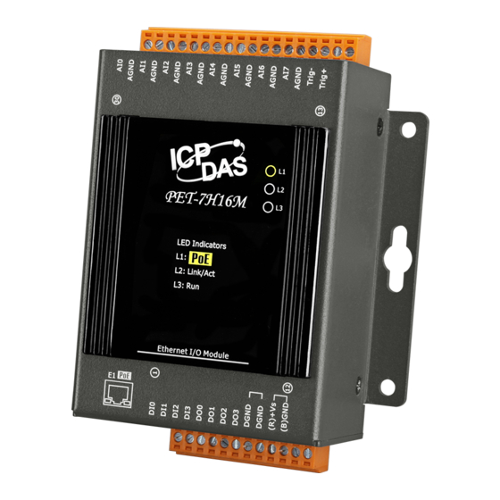
1.3. Overview PET-7H16M is equipped with several interfaces and peripherals that can be integrated with external systems. Here is an overview of the components and its descriptions. J2 Connector (Pin 13 ~ 30) LED Indicators Reset Button Ethernet Port J1 Connector (Pin 1 ~ 12) PET-7H16M Series User Manual, version 1.0.1 P.14... - Page 15 LED Indicators The PET-7H16M has 3 LED indicators shown as below. LED Indicator LED Action Meaning When unit power is supplied via PoE. Ethernet link detected Link/ACT No Ethernet link detected Flashing Ethernet packet received Flashing Firmware is running Tips &...
- Page 16 JP1 Connector The JP1 connector has 12 pins arranged in 1 row. For more detailed information regarding the pin assignments of the J1 Connector, please refer to “1.2. Specification” The pin assignments of the connector are as follows: Signal Direction Description DI0 ~ DI3...
- Page 17 JP2 Connector The JP2 connector has 18 pins arranged in 1 row. For more detailed information regarding the pin assignments of the J2 Connector, please refer to “1.2. Specification” The pin assignments of the connector are as follows: Signal Direction Description AI0 ~ AI7...
- Page 18 The table below lists the default settings after pressing reset button. Network Settings Data Item Factory Default Settings 192.168.255.1 Gateway 192.168.0.1 Mask 255.255.0.0 DHCP Disable Gain/offset value of AI calibration Factory Default Setting Original factory calibration value Account Management Factory Default Setting A default user account consists of an account name “Admin”...
-
Page 19: Wiring Diagram
1.4. Wiring Diagram The wiring diagram of the PET-7H16M is illustrated on the following figure. Analog Input (Voltage) Digital ON State OFF State Input/Counter Readback as 1 Readback as 0 Wet Contact (Sink) ON State OFF State Digital Output Readback as 1 Readback as 0 Open Collector (Sink) -
Page 20: Block Diagram
1.5. Block Diagram PET-7H16M functions are illustrated in the block diagram shown here. -
Page 21: Dimension
1.6. Dimension The diagrams below provide the dimensions of the PET-7H16M to use in defining your enclosure specifications. All dimensions are in millimeters. -
Page 22: Getting Started
2. Getting Started If you are a new user, begin with this chapter, it includes a guided tour that provides a basic overview of installing, configuring and using the PET-7H16M. Before starting any task, please check the package contents. If any of the following package contents are missing or damaged, contact your dealer on distributor. -
Page 23: Mounting The Hardware
2.1. Mounting the Hardware The PET-7H16M can be mounted either directly to a wall/panel. Step 1: Use the included screws and a screw driver to attach the PET-7H16M to the wall/panel Step 2: Fasten the screws securely PET-7H16M Series User Manual, version 1.0.1 P.23... -
Page 24: Deploying A Basic Pet-7H16M System
2.2. Deploying a Basic PET-7H16M System Here is a simple application for using the PET-7H16M that is shown below. There are two ways for the PET-7H16M module getting the power. One is through Ethernet by a PoE switch; the other is as usual through wiring by an external power. External power should range from +12 VDC to 48 VDC. - Page 25 External Power supply i. Connect PC to the Ethernet port via the Ethernet switch. ii. Connect the power supply to the switch and PET-7H16M. PET-7H16M Series User Manual, version 1.0.1 P.25...
-
Page 26: Installing The Et-7H16 Utility
2.3. Installing the ET-7H16 Utility The ET-7H16 Utility is a useful tool that provides a quick and easy way to update firmware, configure Ethernet settings, and download files to PET-7H16M from PC. Refer to chapter 4.2. ET-7H16 Utility for more details.. Step1: Get the ET-7H16 Utility tool The ET-7H16 Utility can be obtained from our FTP site: http://ftp.icpdas.com/pub/cd/6000cd/napdos/et7h16/tools/utility... -
Page 27: Using Et-7H16 Utility To Assign An Ip Address
2.4. Using ET-7H16 Utility to Assign an IP address The PET-7H16M is an Ethernet device, which comes with a default IP address, therefore, you must first assign a new IP address to the PET-7H16M. The factory default IP settings are as follows: Item Default IP Address... - Page 28 Step 2: Press choose “Search” from the “Tools” menu After choosing Search from Tools menu, that will search all of the PET-7H16M modules on your network. Step 3: Choose the field “192.168.255.1” and then choose “IP setting” from the toolbar Choose default value “192.168.255.1”...
- Page 29 Step 4: Assign a new IP address and then choose “Set” button You only can manually assign an IP address. Step 5: Click “OK” button When the setup is completed, click the "OK" button. Step 6: Wait for PET-7H16M reboot PET-7H16M Series User Manual, version 1.0.1 P.29...
-
Page 30: Operation
3. Operation Once connected to the network, the PET-7H16M module can be remotely accessed and configured through software from anywhere on the network and the sampling data only can be acquired by software over Ethernet. So far, the device doesn’t operate as a stand-along data logger. The only one connection at a time is allowed to acquire data from PET-7H16M. -
Page 31: Continuous Acquisition
3.1. Continuous Acquisition 3.1.1. Software AD Trigger In continuous acquisition and software AD trigger, Send a start command from PC over the Ethernet to PET-7H16M to start the AD conversion. The analog input value is continuously acquired and converted to digital data. The data accumulated to a network packet size returns to the PC. - Page 32 PET-7H16M Series User Manual, version 1.0.1 P.32...
-
Page 33: External Clock Ad Trigger
3.1.2. External clock AD trigger In this trigger, send a start command from PC over the Ethernet to PET-7H16M to start the acquisition. The A/D conversion is started actually when the external clock signal is input. The AI value converted to digital data followed the external clock sampling rate and the data accumulated to a network packet size returns to the PC. - Page 34 PET-7H16M Series User Manual, version 1.0.1 P.34...
-
Page 35: N Sample Acquisition
3.2. N Sample Acquisition 3.2.1. Software AD Trigger In N sample acquisition and software AD trigger, Send a start command from PC over the Ethernet to PET-7H16M to start the AD conversion. The analog input value is continuously acquired and converted to digital data until the total number of samples reaches. -
Page 36: External Digital Trigger
3.2.2. External Digital Trigger There are two external digital trigger, Pre-trigger and Post-trigger. Pre-trigger This trigger type is used when you want to collect data before an external trigger event. Send a start command from PC over the Ethernet to PET-7H16M to start the AD conversion. The analog input value is continuously acquired and converted to digital data. - Page 37 CON1 Ethernet … Sampling FIFO Memory Hold External Pre/Post trigger Internal Clock Clock Trig PET-7H16M Series User Manual, version 1.0.1 P.37...
-
Page 38: Tools And Sdks
4. Tools and SDKs PET-7H16M supports a number of external tools to aid in developing your applications 4.1. LabVIEW LabVIEW is the best way to acquire, analyze, and present data. LabVIEW delivers a graphical development environment that can be used to quickly build data acquisition quickly, instrumentation and control systems, boosting productivity and saving development time. -
Page 39: Et-7H16 Utility
4.2. ET-7H16 Utility ET-7H16 utility is used to graphically display and easily data logging for ET-7H16 module. ET-7H16 Utility tool as ET-7H16 Data Logger ET-7H16 Data Logger provides a single ET-7H16 connect as Data Logger function. When connect to ET-7H16, it will get the parameters of gain and offset for calibration, they are used to calibrate the raw data from ET-7H16. - Page 40 System requirement Minimum system requirements for ET-7H16 utility are given below: 266MHz 32-bit(x86) or 64-bit(x64) processor 64 MB of system memory Support for Super VGA graphics At least 20 MB of available space (Need more) Microsoft Windows 2000 or later(32-bit or 64-bit Windows Operating System) Operating system of Windows requirement ...
-
Page 41: Sdk Api
4.3. SDK API This chapter provides a brief overview of ET-7H16 APIs that have been designed for ET-7H16. ET-7H16 SDK library supports 32/64 bit Windows 2003/Vista/7/8/10. Get the latest version of ET-7H16 SDK library at the location below. The latest version of the installation package from FTP site listed as following FTP: ftp://ftp.icpdas.com/pub/cd/6000cd/napdos/et7h16/tools/dll File Description... - Page 42 The following API functions are used to access ET-7H16 module. SDK Functions .NET Functions Description AddCmdClient ET7HLogger.AddCmdClient Create a connection to set/get parameters. AddDataClient ET7HLogger.AddDataClient Create a connection for transferring data. RemoveCmdClient ET7HLogger.SetPWMFrequency Close the TCP connection of command port. RemoveDataClient ET7HLogger.GetPWMFrequency Close the TCP connection of data...
- Page 43 C# Samples The ET-7H16 C# demo includes the following samples that demonstrate the use of the ET-7H16 Standard APIs in a C# language environment. The following samples can be found by downloading the latest version from ICP DAS web site. For C# applications, these demo programs can be obtained from: http://ftp.icpdas.com/pub/cd/6000cd/napdos/et7h16/tools/dll/demo/c# ...
-
Page 44: Web Applications
5. Web Applications The PET-7H16M contains an advanced web configuration system that provides users with access PET-7H16M applications through a standard web browser. Note: The web page function is only suitable for configuration settings. Do not enable this TCP communication when the module is acquitting the data via Ethernet. Logging in to the PET-7H16M Web site You can log in to the PET-7H16M web site from any computer that has Internet access. - Page 45 Step 4 : Welcome to PET-7H16M web site After logging into the PET-7H16M web site, the welcome page will appear. This site serves several functions. You can easily access these functions through the menu on the left side. The Overview of the Main menu provides a brief introduction and explanation of this site.
-
Page 46: Overview
5.1. Overview The Overview links to the welcome page that provides functions to monitor necessary system information of PET-7016M. The information is the most important note of version control for upgrading system. This page provides basic information about the PET-7H16M. ... -
Page 47: Configuration
5.2. Configuration The Configuration menu consists of the following menu: Network Settings: This menu links to the Network Settings page that allows you to access the IP settings. Basic Settings: This menu links to the Basic Settings page that allows you to configure the basic information of this site. -
Page 48: Network Settings
5.2.1. Network Settings The Network Settings page provides functions to configure either DHCP (Roaming) or manually configured (Static) network settings. Manually Configured Network Settings 1. Disable the DHCP 2. Assign an IP address 3. Click SUBMIT to finished configuring the network settings PET-7H16M Series User Manual, version 1.0.1 P.48... -
Page 49: Basic Settings
5.2.2. Basic Settings The Basic Settings page provides the following functions: Configure the module information Configure the web site information Reset all settings to default PET-7H16M Series User Manual, version 1.0.1 P.49... - Page 50 5.2.2.1. Configuring the Module Information The module information includes the following data items: ● Module Name: The name of the module that can be modified. It has an initial value depending on the name of the module. ● Module Information: The module information indicates the name of the alias that is used to identify the module.
- Page 51 5.2.2.2. Configuring the Web site Information The module information includes the following data items: ● Page Header Information (First line) and Page Header Information (Second line): The title of the website that can be modified; you can view the title information in the top-left corner. The title information can be determined as follows: Page Header Information (First line) Page Header Information (Second line)
- Page 52 To configure the web site information 1. Enter the web site information 2. Click Submit to finish configuring the module information PET-7H16M Series User Manual, version 1.0.1 P.52...
- Page 53 5.2.2.3. Resetting All Settings to the Factory Default According to the menu selection of this web, the reset function can be divided into the following categories. You can use this function to reset the settings to their factory default. Configuration ...
- Page 54 The table below lists the factory default settings of the configuration menu. Network Settings Data Item Factory Default Settings 192.168.255.1 Gateway 192.168.0.1 Mask 255.255.0.0 DHCP Disable Basic Settings Data Item Factory Default Setting Module Name Depending on the module name Module Information Empty Top page Information (First line)
-
Page 55: Authentication
5.3. Authentication The Authentication menu consists of the following menu: Account Management: This menu links to the Privilege management page that allows you to manage the user accounts and their privileges. Accessible IP Settings: This menu links to the IP filter Settings page that allow you to control access to the web site PET-7H16M Series User Manual, version 1.0.1... -
Page 56: Account Management
5.3.1. Account Management The Basic Settings page provides the following functions: Configure the user accounts Load the factory default user account PET-7H16M Series User Manual, version 1.0.1 P.56... - Page 57 5.3.1.1. Configuring the user accounts The PET-7H16M web site supports up to 5 user accounts. A built-in administrator account The built-in Administrator is basically a setup and disaster recovery account that can be deleted. You can change the administrator account’s password. ...
- Page 58 To Create an User Account When you create user accounts, you can Enable or Disable user accounts. 1. Enter the user account information, and then select the enable checkbox 2. Click SUBMIT to finish configuring the user accounts PET-7H16M Series User Manual, version 1.0.1 P.58...
- Page 59 5.3.1.2. Loading the factory default user accounts The PET-7H16M has a built-in administrator account named Admin that is created when it is installed by default. The default account cannot be deleted. Click RESET SETTINGS to configure the user account to the factory default settings. PET-7H16M Series User Manual, version 1.0.1 P.59...
-
Page 60: Accessible Ip Settings
5.3.2. Accessible IP Settings The IP filter Settings page provides the following functions: Configure IP filtering PET-7H16M Series User Manual, version 1.0.1 P.60... - Page 61 To Configure the IP filter The PET-7H16M with an IP filter that enables you to restrict or grant user access based an IP filter list you create. The filter can be enabled or disable by selecting the Enable the IP filter table checkbox Tips &...
- Page 62 Method 1 : Allows access from a single IP address 1. Select the Enable the IP filter table 2. Enter the same IP address in the From (IP Address) and To (IP Address) 3. Select the Active the rule checkbox 4.
- Page 63 2. Enter a range of IP addresses in the From (IP Address) and To (IP Address) 3. Select the Active the rule checkbox 4. Click SUBMIT to finish configuring the IP filter list PET-7H16M Series User Manual, version 1.0.1 P.63...
-
Page 64: Web Hmi
5.4. Web HMI The Web HMI menu consists of the following menu: Web HMI: This menu links to the I/O monitor page that allows you to monitor and control the I/O status on PET-7H16M module remotely. By default, this page displays summary information about I/O channels that are classified according to the module type. -
Page 65: Modbus Applications
6. Modbus Applications The PET-7H16M is a Modbus device that allows you to access terminals data via Ethernet and communicates using a master-slave technique in which only one device (the master) can initiate transactions (called queries). The other devices (slaves) respond by supplying the requested data to the master, or by taking the action requested in the query. - Page 66 Register Map Modbus devices usually include a Register Map. Modbus functions operate on register map registers to monitor, configure, and control module I/O. The users should refer to the register map for the PET-7H16M to gain a better understanding of its operation. PET-7H16M Series User Manual, version 1.0.1 P.66...
- Page 67 0xxxx address table Begin Registers Access Points Description Range address per Point Type 0 = off Digital Out 1 = on The data order of long value 0: low byte, high byte to Modbus register 1: high byte, low byte Reset the I/O settings to the 1: Reset W (Pulse)
- Page 68 3xxxx address table Begin Registers Access Points Description Range address per Point Type Analog Input word -32768 ~ +32767 Use Channel Gain Value word 0 ~ 65535 Use Channel Offset Value word -32768 ~ +32767 Number of the DI channel word 0 ~ 65535 Number of the DO channel...
- Page 69 4xxxx address table Begin Registers Access Points Description Range address per Point Type 0: +/- 5V Set AI type word R/W/E 1: +/- 10V Scan Channel Count word 1 ~ 8 0: Software start 1: External Trigger Trigger Type word 2: Post-Trigger R/W/E...
-
Page 70: Updates
7. Updates The firmware is stored in flash memory and can be updated to fix functionality issues or add additional features, so we advise you to periodically check the ICP DAS web site for the latest updates. Step 1 : Get the latest version of the firmware and the autoexec.bat file The latest version of the PET-7H16M firmware and autoexec.bat file can be obtained from: http://ftp.icpdas.com/pub/cd/6000cd/napdos/et7h16/firmware/ Step 2 : Run the ET-7H16 Utility... - Page 71 Step 3 : Establish a connection to PET-7H16M Click “Connect” button Step 4 : Choose “Erase Disk” from the “Command” menu After establishing a connection, then choose upload Firmware from Tools menu. Then confirm the IP of PET-7H16M, then click “…” button. PET-7H16M Series User Manual, version 1.0.1 P.71...
- Page 72 Step 5 : Choose the PET7H16M_VXXXX.hex to upload Select PET7H16M_VXXXX.hex to upload, then click "Open File" and then click "Upload". Step 6 : End of upload After uploading the file, the progress bar will be as shown below.. Tips & Warnings You have to reboot the PET-7H16M after uploading the firmware.
-
Page 73: Calibration
8. Calibration When shipped from the factory, PET-7H16M is already fully calibrated, including the calibration coefficients that are stored in the onboard EEPROM. For a more precise application of voltages in the field, the procedure described below provides a method that allows the board installed in a specific system to be calibrated so that the correct voltages can be achieved for the field connection. - Page 74 Step 1: Entering the IP and Port, and click Connect After the connection is successful, the firmware version will be read back. PET-7H16M Series User Manual, version 1.0.1 P.74...
- Page 75 Step 2:Output voltage 4.8V to ch0 ~ ch7 and the meter, and select +/-5V in Gain combo box. Enter the value reading from the meter in Meter 1 textbox (the following example is 4.7990) Tips & Warnings The range of output voltage is 5V~0V and it’s better to output voltage value near to 5V.
- Page 76 Step 3: Click Point_1 button and get the raw data of each channel as following Step 4:Output a voltage, -4.8V to ch0 ~ ch7 and the meter, enter the value reading from meter in Meter 2 textbox (the following example is -4.7916) PET-7H16M Series User Manual, version 1.0.1 P.76...
- Page 77 Step 5: Click Point_2 button and get the raw data of each channel as following Step 6: Select +/- 10V in Gain combo box. Step 7: Repeat the Step2 ~ Step5, and the upper limit voltage outputs 9.8V in Step 2 and the lower limit voltage outputs -9.8V in Step 5.
- Page 78 Step 8: After completing the calibration, click on ShowGainOffset button to read Gain and Offset value. PET-7H16M Series User Manual, version 1.0.1 P.78...
- Page 79 Appendix A. What is Modbus TCP/IP? Modbus is a communication protocol developed by Modicon in 1979. Different versions of Modbus used today include Modbus RTU (based on serial communication like RS485 and RS232), Modbus ASCII and Modbus TCP, which is the Modbus RTU protocol embedded into TCP packets.
- Page 80 A.1. Address The first byte of information in the message structure of Modbus is the receiver’s address. The valid addresses are in the range of 0 to 247. Addresses from 1 to 247 are given to individual Modbus devices and 0 is used for broadcast. Reference Description 0xxxx...
- Page 81 A.3. Data Field The data field consists of messages sent between master and slave. The messages contain additional information about the action to be taken by the slave or any information requested by the slave. When the slave does not require this information the data field can be nonexistent. A.4.
-
Page 82: Appendix B. Analog Input Type And Data Format Table
Appendix B. Analog Input Type and Data Format Table Type Code Input Range Data Format +F.S -F.S Engineering Unit +10000 -10000 -10 to +10V 2’s comp HEX 7FFF 8000 Engineering Unit +5000 -5000 -5 to +5V 2’s comp HEX 7FFF 8000 PET-7H16M Series User Manual, version 1.0.1 P.82... -
Page 83: Appendix C. Troubleshooting
Appendix C. Troubleshooting A number of common problems are easy to diagnose and fix if you know the cause. Symptom/Problem Possible cause Solution The Run LED doesn’t light Internal power has failed Return the module for repair. The Run LED indicator is ON The module has possibly Reboot the module (light), but not flashing. -
Page 84: Appendix D. Revision History
Appendix D. Revision History This chapter provides revision history information to this document. The table below shows the revision history. Revision Date Description 1.0.1 January 2019 Initial issue PET-7H16M Series User Manual, version 1.0.1 P.84...
Need help?
Do you have a question about the ET-7H16M Series and is the answer not in the manual?
Questions and answers