
Subscribe to Our Youtube Channel
Related Manuals for DEUTSCHMANN AUTOMATION UNIGATE CX-CANopen - DeviceNet


Summary of Contents for DEUTSCHMANN AUTOMATION UNIGATE CX-CANopen - DeviceNet
- Page 1 Manual Universal Fieldbus-Gateway ® UNIGATE CX-CANopen-(Mapping) - DeviceNet Deutschmann Automation GmbH & Co. KG www.deutschmann.de | wiki.deutschmann.com...
- Page 2 Handbuch Art.-Nr.: V4419E...
-
Page 3: Table Of Contents
Deutschmann Automation GmbH & Co. KG Information on CE marking of the module ....8 EU Directive EMC ......8 Scope of application . - Page 4 Deutschmann Automation GmbH & Co. KG Implemented Protocols - DeviceNet ....22 7.2.1 Protocol Delta exchange ......22 The trigger byte .
- Page 5 Deutschmann Automation GmbH & Co. KG 11.1.1 Mounting ........35 11.1.2 Removal...
- Page 6 Deutschmann Automation GmbH & Co. KG 18 Servicing ....... . . 49 18.1 Returning a device .
- Page 7 We would be pleased to receive any improvement proposals which you may have. Copyright Copyright (C) Deutschmann Automation GmbH & Co. KG 1997 – 2020. All rights reserved. This document may not be passed on nor duplicated, nor may its contents be used or disclosed unless expressly permitted.
-
Page 8: Information On Ce Marking Of The Module
The EU Declarations of Conformity are available at the following location for perusal by the responsible authorities in accordance with the EU Directive, Article 10: Deutschmann Automation GmbH & Co. KG, Carl-Zeiss-Straße 8, 65520 Bad Camberg, Ger- many. Scope of application The modules are designed for use in the industrial sector and comply with the following requirements. -
Page 9: Information For The Machine Manufacturers
Deutschmann Automation GmbH & Co. KG Information for the machine manufacturers Information for the machine manufacturers Introduction ® The UNIGATE module does not constitute a machine as defined by the EU "Machinery“ Directive. Consequently, the module does not have a Declaration of Conformity in relation to the EU Machinery Directive. -
Page 10: Introduction
Introduction Deutschmann Automation GmbH & Co. KG Introduction ® The UNIGATE CX-CANopen (Mapping) - DeviceNet module serves to adapt a CANopen inter- face to DeviceNet according to „DeviceNet Specification Release 2.0“. In this application it acts ™ as a gateway and works as DeviceNet „Group 2 Only Slave“. It can be operated by any standard- compliant master. -
Page 11: Operation Modes Of The Gateway
Deutschmann Automation GmbH & Co. KG Operation modes of the Gateway Operation modes of the Gateway Run mode ® When delivered, the UNIGATE CX is in RUN mode. The following functions can be used in RUN mode: • Data exchange •... -
Page 12: The Debug-Interface
The Debug-interface Deutschmann Automation GmbH & Co. KG The Debug-interface Overview of the Debug-interface ® The UNIGATE features a Debug-interface, that allows a step-by-step processing of a Script. Normally this interface is only required for the development of a Script. -
Page 13: Mode Of Operation Of The System
Communication can be split into seven layers, Layer 1 to Layer 7, in accordance with the ISO/ OSI model. The Deutschmann Automation Gateways convert Layers 1 and 2 of the customized bus system (RS485 / RS232 / RS422) to the corresponding Fieldbus system. Layers 3 to 6 are blank, and Layer 7 is converted in accordance with chapter 25.3. -
Page 14: Implemented Protocols In Unigate Cx C4Map
Data structure ® The mapping in the gateway can be configured using the supplied WINGATE software. This gateway module from the UNIGATE series from Deutschmann Automation allows a cou- ® pling between fieldbus and CANopen ® The gateway behaves on the CANopen side as a standard-compliant master and on the DeviceNet side as a standard-compliant slave. -
Page 15: Configuration Of The Mapping
Deutschmann Automation GmbH & Co. KG Implemented protocols in UNIGATE® CX C4Map 7.1.2.1 Configuration of the mapping ® To create or edit such a mapping, connect the UNIGATE in configuration mode (see Chapter ® 23.3) to the PC via the RS232 interface and start the "WINGATE "... -
Page 16: Node Guarding
Implemented protocols in UNIGATE® CX C4Map Deutschmann Automation GmbH & Co. KG Only COB-IDs from the range 101H..580H can be used for the PDO map- ® pings (see DS301 specification for CANopen 7.1.2.2 Node Guarding ® ® If a CANopen... -
Page 17: Display Of The Node Guarding States
Deutschmann Automation GmbH & Co. KG Implemented protocols in UNIGATE® CX C4Map 7.1.2.3 Display of the node guarding states Node guard mapping is used to display the node guard states of the individual slaves to the field- bus. 8 slaves are always represented in one byte; So exactly one bit of information is reserved for a slave. -
Page 18: Gateway Control Byte
Implemented protocols in UNIGATE® CX C4Map Deutschmann Automation GmbH & Co. KG 7.1.2.5 Gateway Control Byte Some properties of the gateway can be controlled by fieldbus data. For this purpose, the infor- mation must be transferred from the fieldbus to the gateway, i.e. it must be in the gateway's entrance area. -
Page 19: Sdo Obj Mapping
Deutschmann Automation GmbH & Co. KG Implemented protocols in UNIGATE® CX C4Map 7.1.2.10 SDO Obj Mapping SDO transmission via a "window" in the fieldbus (FB). The following fixed data record structure is used in the FB, which is mapped into the FB data from the FB index. A distinction is made bet-... -
Page 20: Slave Mode
Implemented protocols in UNIGATE® CX C4Map Deutschmann Automation GmbH & Co. KG Please note: The counting starts with index "0" = 1st byte, i. H. in our example the "8" corresponds to the 9th byte! ® We want to query the manufacturer hardware version of a connected CANopen slave (object ®... -
Page 21: Communication Cycle Period (Object 1006H)
Deutschmann Automation GmbH & Co. KG Implemented protocols in UNIGATE® CX C4Map 7.1.2.13 Communication cycle period (object 1006h) This object provides the communication cycle time. This period defines the SYNC interval. The function can be permanently activated via the Sync. Time (ms) Obj 1006h can be activated or set with WINGATE or temporarily via third-party engineering software. -
Page 22: Implemented Protocols - Devicenet
Implemented protocols in UNIGATE® CX C4Map Deutschmann Automation GmbH & Co. KG Implemented Protocols - DeviceNet In addition to the "Delta exchange" protocol, the universal script also contains other protocols. However, these cannot be used for communication with the "CANopen (Mapping)" protocol. -
Page 23: The Length Byte
Deutschmann Automation GmbH & Co. KG Implemented protocols in UNIGATE® CX C4Map The length byte The user can configure whether the transmit length is also to be stored as a byte in the input/out- → put data area (Fieldbus lengthbyte active). -
Page 24: Hardware Ports, Switches And Leds Canopen (Mapping)
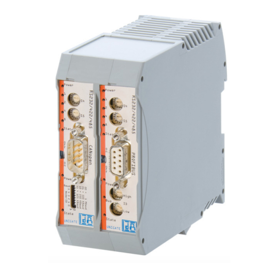
Hardware ports, switches and LEDs CANopen (Mapping) Deutschmann Automation GmbH & Co. KG Hardware ports, switches and LEDs CANopen (Mapping) Device labeling Picture 1. Terminal labeling and termination Picture 2: Front panel: Rotary switches, LEDs and termination CO In case the front panel should pop out it does not affect the device’s function or quality. -
Page 25: Connector Supply Voltage And Debug-Interface
Deutschmann Automation GmbH & Co. KG Hardware ports, switches and LEDs CANopen (Mapping) 8.2.2 Connector supply voltage and DEBUG-interface Pin assignment X1 (4-pin screw-plug connector, on the bottom side, at the back) Pin No. Name Function UB (Pwr) 10..33 V supply voltage / DC... -
Page 26: Led "(Bus) State
Hardware ports, switches and LEDs CANopen (Mapping) Deutschmann Automation GmbH & Co. KG 8.3.2 LED “(Bus) State“ Indicator states and flash rates The following Indicator states are distinguished: LED on constantly on LED off constantly off LED flickering iso-phase on and off with a frequency of approximately 10 Hz: on for approxi- mately 50 ms and off for approximately 50 ms. -
Page 27: Led "Power
Deutschmann Automation GmbH & Co. KG Hardware ports, switches and LEDs CANopen (Mapping) ® CANopen RUN LED (green) ® ® The CANopen RUN LED indiates the status of the CANopen network state machine CAN RUN LED State Description Flickering AutoBaud/LSS Auto Baudrate detection in progress or LSS services in progress (alternately flickering with RUN LED). -
Page 28: Termination (Canopen )
Hardware ports, switches and LEDs CANopen (Mapping) Deutschmann Automation GmbH & Co. KG 8.4.2 Termination (CANopen ® ® If the Gateway is operated as the first or last physical device in the CANopen , there must be a bus termination at this Gateway. In order to do this, either a bus terminating resistor must be acti- vated in the connector or the resistor (220 ) integrated in the Gateway must be activated. -
Page 29: Hardware Ports, Switches And Leds Devicenet
Deutschmann Automation GmbH & Co. KG Hardware ports, switches and LEDs DeviceNet Hardware ports, switches and LEDs DeviceNet Device labeling Picture 1: Terminal labeling and termination Picture 2: Front panel: Rotary switches, DIP-Switch and LEDs In case the front panel should pop out it does not affect the device’s function or quality. -
Page 30: Connector Supply Voltage And Debug-Interface
Hardware ports, switches and LEDs DeviceNet Deutschmann Automation GmbH & Co. KG Connector supply voltage and DEBUG-interface 9.1.1.2 Pin assignment X2 (4-pole screw-plug connector, on the bottom side, at the back) Pin No. Name Function UB (Out) 10..33 V supply voltage / DC... -
Page 31: Led "Power
Deutschmann Automation GmbH & Co. KG Hardware ports, switches and LEDs DeviceNet 9.2.3 LED "Power" This LED is connected directly to the (optionally also electrically isolated) supply voltage of the serial interface (RS232/422/485). 9.2.4 LED "State" Lights green Data exchange active... -
Page 32: Dip-Switch
Hardware ports, switches and LEDs DeviceNet Deutschmann Automation GmbH & Co. KG 9.3.3 DIP-switch The DIP-switch is used to set the Node-ID and baud rate according to picture 3. Picture 1: DIP-switch ® The Debug cable for UNIGATE As accessory a pre-configured Debug cable is available. The Debug cable connects the Gate- way to Debug and RS. -
Page 33: Error Handling
Deutschmann Automation GmbH & Co. KG Error handling 10 Error handling ® 10.1 Error handling at UNIGATE C4Map If the Gateway detects an error, the error is signalled by the “State“ LED lighting red and, simulta- neously, the error number being indicated by means of LEDs “Error No.“ as shown in the table below. -
Page 34: Error Handling At Unigate ® Cl-Devicenet
Error handling Deutschmann Automation GmbH & Co. KG ® 10.2 Error handling at UNIGATE CL-DeviceNet If the Gateway detects an error, the error is signalled by the “State“ LED lighting red and, simulta- neously, the error number being indicated by means of LEDs “Error No.“ as shown in the table below. -
Page 35: Installation Guidelines
Deutschmann Automation GmbH & Co. KG Installation guidelines 11 Installation guidelines 11.1 Installation of the module The module with the dimensions 23 x 117 x 111 mm resp. 23 x 117 x 117 mm with Option I/O8 (W x D x H) has been developed for switch cabinet use (IP 20) and can thus be mounted only on a standard mounting channel (deep DIN-rail to EN 50022). -
Page 36: Power Supply
Installation guidelines Deutschmann Automation GmbH & Co. KG ® • 9-pin D-SUB plug connector (CANopen a) In the case of standard screw-type terminals, one lead can be clamped per connection point. It is best to then use a screwdriver with a blade width of 3.5 mm to firmly tighten the screw. -
Page 37: Canopen ® Communication Interface
Deutschmann Automation GmbH & Co. KG CANopen® communication interface 12 CANopen communication interface ® 12.1 Bus line with copper cable This interface is located on the module in the form of a 9-pin D-SUB plug on the front side of the housing. -
Page 38: Shielding Of Lines
CANopen® communication interface Deutschmann Automation GmbH & Co. KG 2) Lines must be laid in separate bunches or cable ducts (without minimum clearance). Lines must be laid in separate bunches or cable ducts inside cabinets but on separate cable racks with at least 10 cm clearance outside of cabinets but inside buildings. -
Page 39: Canopen
Deutschmann Automation GmbH & Co. KG CANopen® ® 13 CANopen ® 13.1 Description CANopen ® This specification is based on the CiA Draft Standard 301 (DS301). ® CANopen supports the Standard CAN-frame with 11-bit Identifier. It is not required to support the extended frame with 29-bit Identifier. - Page 40 CANopen® Deutschmann Automation GmbH & Co. KG • Init Object Table • Create Object • Set PDO Communiction • Set PDO Mapping • Write Object ® • Read New CANopen Object Data • Emergency Message ® The software does not support default objects, as at CANopen ®...
-
Page 41: Communication Interface Devicenet
Deutschmann Automation GmbH & Co. KG Communication interface DeviceNet 14 Communication interface DeviceNet 14.1 Bus line with copper cable This interface is located on the module in the form of a 5-pin screw-plug-connector on the lower side of the housing. - Page 42 Communication interface DeviceNet Deutschmann Automation GmbH & Co. KG Interference currents on cable shields are discharged to earth via the shielding bus which is con- nected conductively to the chassis or housing. A low-impedance connection to the PE wire is particularly important in order to prevent these interference currents themselves becoming an interference source.
-
Page 43: Devicenet
Deutschmann Automation GmbH & Co. KG DeviceNet 15 DeviceNet 15.1 The Product Code The device’s Product Code is an unsigned integer value (UINT) with values ranging between 0 and 65535 and it is included in the first instance (01 hex) of the Identity Object (01 hex) in attri- bute 3 (0003 hex). -
Page 44: Technical Data
Technical data Deutschmann Automation GmbH & Co. KG 16 Technical data 16.1 Device data The technical data of the module is given in the table below. No. Parameter Data Explanations Location Switch cabinet DIN-rail mounting Enclosure IP20 Protection against foreign... -
Page 45: Interface Data
Deutschmann Automation GmbH & Co. KG Technical data 16.1.1 Interface data The table below lists the technical data of the interfaces and ports on the device. The data has been taken from the corresponding Standards. Interface designation RS232-C DeviceNet ®... -
Page 46: Commissioning Guide
Commissioning guide Deutschmann Automation GmbH & Co. KG 17 Commissioning guide 17.1 Note ® Only trained personnel following the safety regulations may commission the UNIGATE 17.2 Components ® You will require the following components to commission the UNIGATE ® •... -
Page 47: Setting The Canopen ® Address And Baud Rate
Deutschmann Automation GmbH & Co. KG Commissioning guide ® 17.6 Setting the CANopen address and baud rate ® Set the CANopen -Node-ID and the baud rate at the fieldbus end of the module on the DIP- switch (see also chapter 27.4.3). -
Page 48: Shield Connection
Commissioning guide Deutschmann Automation GmbH & Co. KG 17.11 Shield connection Earth the top-hat rail onto which the module has been snapped. 17.12 Project planning Use any project planning tool for project planning. If the required EDS file was not supplied with your project planning tool, you can find a sample file in chapter 34.2 or on the Internet at www.deutschmann.de. -
Page 49: Servicing
Deutschmann Automation GmbH & Co. KG Servicing 18 Servicing Should questions arise that are not covered in this manual you can find further information in our • FAQ/Wiki area on our homepage www.deutschmann.com or directly in our Wiki on www.wiki.deutschmann.de If your questions are still unanswered please contact us directly. -
Page 50: Annex
Annex Deutschmann Automation GmbH & Co. KG 19 Annex 19.1 Explanations of the abbreviations General Product group CL (Compact Line) Product group CM (CANopen Line) Product group CX Product group EL (Ethernet Line) Product group FC (Fast Connect) Galvanic separation RS-side... -
Page 51: Hexadecimal Table
Deutschmann Automation GmbH & Co. KG Annex product) ® PBDPX ProfibusDP-version X (see comparison table UNIGATE IC for the respective product) PBDPV0 = ProfibusDPV0 PBDPV1 = ProfibusDPV1 Serial RS232/485/422 19.2 Hexadecimal table Decimal Binary 0000 0001 0010 0011 0100 0101...
Need help?
Do you have a question about the UNIGATE CX-CANopen - DeviceNet and is the answer not in the manual?
Questions and answers