
Related Manuals for DEUTSCHMANN AUTOMATION UNIGATE CX-CANopen-(Mapping) - PROFIBUS DP


Summary of Contents for DEUTSCHMANN AUTOMATION UNIGATE CX-CANopen-(Mapping) - PROFIBUS DP
- Page 1 Manual Universal Fieldbus-Gateway ® UNIGATE CX-CANopen-(Mapping) - PROFIBUS DP Deutschmann Automation GmbH & Co. KG www.deutschmann.de | wiki.deutschmann.com...
- Page 2 Handbuch Art.-Nr.: V4412E...
-
Page 3: Table Of Contents
Deutschmann Automation GmbH & Co. KG Information on CE marking of the module ....8 EU Directive EMC ......8 Scope of application . - Page 4 Deutschmann Automation GmbH & Co. KG Implemented Protocols - PROFIBUS DP ....22 7.2.1 Protocol Delta exchange ......22 The trigger byte .
- Page 5 Deutschmann Automation GmbH & Co. KG 11 Installation guidelines ......35 11.1 Installation of the module ......35 11.1.1 Mounting .
- Page 6 Deutschmann Automation GmbH & Co. KG 16.6.5 Project planning ....... . . 51 16.7 Setting the PROFIBUS address...
- Page 7 We would be pleased to receive any improvement proposals which you may have. Copyright Copyright (C) Deutschmann Automation GmbH & Co. KG 1997 – 2020. All rights reserved. This document may not be passed on nor duplicated, nor may its contents be used or disclosed unless expressly permitted.
-
Page 8: Information On Ce Marking Of The Module
The EU Declarations of Conformity are available at the following location for perusal by the responsible authorities in accordance with the EU Directive, Article 10: Deutschmann Automation GmbH & Co. KG, Carl-Zeiss-Straße 8, 65520 Bad Camberg, Ger- many. Scope of application The modules are designed for use in the industrial sector and comply with the following... -
Page 9: Information For The Machine Manufacturers
Deutschmann Automation GmbH & Co. KG Information for the machine manufacturers Information for the machine manufacturers Introduction ® The UNIGATE module does not constitute a machine as defined by the EU "Machinery“ Directive. Consequently, the module does not have a Declaration of Conformity in relation to the EU Machinery Directive. -
Page 10: Introduction
Introduction Deutschmann Automation GmbH & Co. KG Introduction ® The UNIGATE CX-CANopen (Mapping) - PROFIBUS DP module serves to adapt a CANopen interface to PROFIBUS according to EN 50 170. In this application it acts as a gateway and works as a CANopen with master functionality on one side and as a PROFIBUS DP slave on the other side. -
Page 11: Operation Modes Of The Gateway
Deutschmann Automation GmbH & Co. KG Operation modes of the Gateway Operation modes of the Gateway Run mode ® When delivered, the UNIGATE CX is in RUN mode. The following functions can be used in RUN mode: • Data exchange •... -
Page 12: The Debug-Interface
The Debug-interface Deutschmann Automation GmbH & Co. KG The Debug-interface Overview of the Debug-interface ® The UNIGATE features a Debug-interface, that allows a step-by-step processing of a Script. Normally this interface is only required for the development of a Script. -
Page 13: Mode Of Operation Of The System
Communication can be split into seven layers, Layer 1 to Layer 7, in accordance with the ISO/ OSI model. The Deutschmann Automation Gateways convert Layers 1 and 2 of the customized bus system (RS485 / RS232 / RS422) to the corresponding Fieldbus system. Layers 3 to 6 are blank, and Layer 7 is converted in accordance with chapter 24.3. -
Page 14: Implemented Protocols In Unigate Cx C4Map
Data structure ® The mapping in the gateway can be configured using the supplied WINGATE software. This gateway module from the UNIGATE series from Deutschmann Automation allows a cou- ® pling between fieldbus and CANopen ® The gateway behaves on the CANopen... -
Page 15: Configuration Of The Mapping
Deutschmann Automation GmbH & Co. KG Implemented protocols in UNIGATE® CX C4Map 256 mappings are currently possible (128 Tx and 128 Rx mappings). The data is transferred as PDOs. A maximum of 16 Tx and 16 RX PDOs can be set. Each PDO can have up to 8 bytes (i.e. -
Page 16: Node Guarding
Implemented protocols in UNIGATE® CX C4Map Deutschmann Automation GmbH & Co. KG ® When mapping from fieldbus to CANopen , several mappings can be configured for each fieldbus byte. The total number of these multiple mappings must not exceed 31. -
Page 17: Display Of The Node Guarding States
Deutschmann Automation GmbH & Co. KG Implemented protocols in UNIGATE® CX C4Map 7.1.2.3 Display of the node guarding states Node guard mapping is used to display the node guard states of the individual slaves to the field- bus. 8 slaves are always represented in one byte; So exactly one bit of information is reserved for a slave. -
Page 18: Gateway Control Byte
Implemented protocols in UNIGATE® CX C4Map Deutschmann Automation GmbH & Co. KG 7.1.2.5 Gateway Control Byte Some properties of the gateway can be controlled by fieldbus data. For this purpose, the informa- tion must be transferred from the fieldbus to the gateway, i.e. it must be in the gateway's entrance area. -
Page 19: Sdo Obj Mapping
Deutschmann Automation GmbH & Co. KG Implemented protocols in UNIGATE® CX C4Map 7.1.2.10 SDO Obj Mapping SDO transmission via a "window" in the fieldbus (FB). The following fixed data record structure is used in the FB, which is mapped into the FB data from the FB index. A distinction is made bet-... -
Page 20: Slave Mode
Implemented protocols in UNIGATE® CX C4Map Deutschmann Automation GmbH & Co. KG 2. Byte 2. Byte 3. Byte 3. Byte 4. Byte 4. Byte 5. Byte 5. Byte 6. Byte 6. Byte 7. Byte 7. Byte 8. Byte 8. Byte... -
Page 21: Start Phase
Deutschmann Automation GmbH & Co. KG Implemented protocols in UNIGATE® CX C4Map 7.1.2.14 Start phase ® The UNIGATE sends the NMT command "BusStart" every 2 seconds during the start phase; i.e. ® all connected CANopen slaves are set to the "Operational" state. -
Page 22: Implemented Protocols - Profibus Dp
Implemented protocols in UNIGATE® CX C4Map Deutschmann Automation GmbH & Co. KG Implemented Protocols - PROFIBUS DP In addition to the "Delta exchange" protocol, the universal script also contains other protocols. However, these cannot be used for communication with the "CANopen (Mapping)" protocol. -
Page 23: The Length Byte
Deutschmann Automation GmbH & Co. KG Implemented protocols in UNIGATE® CX C4Map The first byte in the Profibus input / output data buffer is used as the trigger byte when this mode is switched on. The length byte It can be configured whether the send length is also stored as a byte in the input / output data area (Fieldbus lengthbyte ->... -
Page 24: Hardware Ports, Switches And Leds Canopen (Mapping)
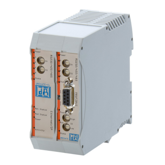
Hardware ports, switches and LEDs CANopen (Mapping) Deutschmann Automation GmbH & Co. KG Hardware ports, switches and LEDs CANopen (Mapping) Device labeling Picture 1. Terminal labeling and termination Picture 2: Front panel: Rotary switches, LEDs and termination CO In case the front panel should pop out it does not affect the device’s function or quality. -
Page 25: Connector Supply Voltage And Debug-Interface
Deutschmann Automation GmbH & Co. KG Hardware ports, switches and LEDs CANopen (Mapping) 8.2.2 Connector supply voltage and DEBUG-interface Pin assignment X1 (4-pin screw-plug connector, on the bottom side, at the back) Pin No. Name Function UB (Pwr) 10..33 V supply voltage / DC... -
Page 26: Led "(Bus) State
Hardware ports, switches and LEDs CANopen (Mapping) Deutschmann Automation GmbH & Co. KG 8.3.2 LED “(Bus) State“ Indicator states and flash rates The following Indicator states are distinguished: LED on constantly on LED off constantly off LED flickering iso-phase on and off with a frequency of approximately 10 Hz: on for approxi-... -
Page 27: Led "Power
Deutschmann Automation GmbH & Co. KG Hardware ports, switches and LEDs CANopen (Mapping) Blinking PRE-OPERATIONAL The device is in the PRE-OPERATIONAL state. OPERATIONAL The device is in the OPERATIONAL state. ® Whilst the device is executing a reset the CANopen RUN LED shall be off. -
Page 28: Debug Cable For Unigate ® Cl
Hardware ports, switches and LEDs CANopen (Mapping) Deutschmann Automation GmbH & Co. KG ® If the Node-ID 0 (which is not allowed in CANopen ) is set on the DIP-Switch, then the Node-ID, which is stored in the EEROM via the Script or WINGATE is used in this case. That way it is also possible to set Node-IDs >... -
Page 29: Hardware Ports, Switches And Leds Profibus Dp
Deutschmann Automation GmbH & Co. KG Hardware ports, switches and LEDs PROFIBUS DP Hardware ports, switches and LEDs PROFIBUS DP Device labeling Picture 1: Terminal labeling and termination Picture 2: Front panel: Rotary switches, LEDs and termination PB In case the front panel should pop out it does not affect the device’s function or quality. -
Page 30: Connector Supply Voltage And Debug-Interface
Hardware ports, switches and LEDs PROFIBUS DP Deutschmann Automation GmbH & Co. KG Connector supply voltage and DEBUG-interface 9.1.1.2 Pin assignment X2 (4-pole screw-plug connector, on the bottom side, at the back) Pin No. Name Function UB (Out) 10..33 V supply voltage / DC... -
Page 31: Led "(Bus) State
Deutschmann Automation GmbH & Co. KG Hardware ports, switches and LEDs PROFIBUS DP 9.2.3 LED "(Bus) State" Lights green PROFIBUS in the state data exchange Flashes green Gateway waits for PROFIBUS communication data Flashes green/red Gateway waits for PROFIBUS parameter data... -
Page 32: Rotary Coding Switches High + Low (Profibus-Id)
Hardware ports, switches and LEDs PROFIBUS DP Deutschmann Automation GmbH & Co. KG 9.2.7.3 Rotary coding switches High + Low (PROFIBUS-ID) With these two switches the Gateway’s Profibus-ID (00... 7D) is set in hexadecimal notation. Please refer to the Annex for a conversion table from decimal to hexadecimal. This value is read in only once when the Gateway is activated.The value can also be read-out or analyzed through... -
Page 33: Error Handling
Deutschmann Automation GmbH & Co. KG Error handling 10 Error handling ® 10.1 Error handling at UNIGATE C4Map If the Gateway detects an error, the error is signalled by the “State“ LED lighting red and, simulta- neously, the error number being indicated by means of LEDs “Error No.“ as shown in the table below. -
Page 34: Error Handling At Unigate ® Cl-Profibus Dp
Error handling Deutschmann Automation GmbH & Co. KG ® 10.2 Error handling at UNIGATE CL-PROFIBUS DP If the Gateway detects an error, the error is signalled by the “State“ LED lighting red and, simulta- neously, the error number being indicated by means of LEDs “Error No.“ as shown in the table below. -
Page 35: Installation Guidelines
Deutschmann Automation GmbH & Co. KG Installation guidelines 11 Installation guidelines 11.1 Installation of the module The module with the dimensions 23 x 117 x 111 mm resp. 23 x 117 x 117 mm with Option I/O8 (W x D x H) has been developed for switch cabinet use (IP 20) and can thus be mounted only on a standard mounting channel (deep DIN-rail to EN 50022). -
Page 36: Power Supply
Installation guidelines Deutschmann Automation GmbH & Co. KG ® • 9-pin D-SUB plug connector (CANopen a) In the case of standard screw-type terminals, one lead can be clamped per connection point. It is best to then use a screwdriver with a blade width of 3.5 mm to firmly tighten the screw. -
Page 37: Canopen ® Communication Interface
Deutschmann Automation GmbH & Co. KG CANopen® communication interface 12 CANopen communication interface ® 12.1 Bus line with copper cable This interface is located on the module in the form of a 9-pin D-SUB plug on the front side of the housing. -
Page 38: Shielding Of Lines
CANopen® communication interface Deutschmann Automation GmbH & Co. KG 2) Lines must be laid in separate bunches or cable ducts (without minimum clearance). Lines must be laid in separate bunches or cable ducts inside cabinets but on separate cable racks with at least 10 cm clearance outside of cabinets but inside buildings. -
Page 39: Canopen
Deutschmann Automation GmbH & Co. KG CANopen® ® 13 CANopen ® 13.1 Description CANopen ® This specification is based on the CiA Draft Standard 301 (DS301). ® CANopen supports the Standard CAN-frame with 11-bit Identifier. It is not required to support the extended frame with 29-bit Identifier. - Page 40 CANopen® Deutschmann Automation GmbH & Co. KG • Init Object Table • Create Object • Set PDO Communiction • Set PDO Mapping • Write Object ® • Read New CANopen Object Data • Emergency Message ® The software does not support default objects, as at CANopen ®...
-
Page 41: Communication Interface Profibus Dp
Deutschmann Automation GmbH & Co. KG Communication interface PROFIBUS DP 14 Communication interface PROFIBUS DP 14.1 Bus line with copper cable This interface is located on the module in the form of a 9-pin D-SUB socket on the front side of the housing. -
Page 42: Shielding Of Lines
Communication interface PROFIBUS DP Deutschmann Automation GmbH & Co. KG 14.2.2 Shielding of lines Shielding is intended to weaken (attenuate) magnetic, electrical or electromagnetic interference fields. Interference currents on cable shields are discharged to earth via the shielding bus which is con- nected conductively to the chassis or housing. -
Page 43: Dpv2
Deutschmann Automation GmbH & Co. KG Communication interface PROFIBUS DP 2. Acyclic data exchange with Class2-Master (e. g.: control unit) This option is optional for a DPV1-Slave as well. Our gateways support this function as a default. By means of this function the Class2-Master can read and write data from the slave acyclically. -
Page 44: Configuration Telegram
Communication interface PROFIBUS DP Deutschmann Automation GmbH & Co. KG If the module detects, during the check, that the maximum permitted input/output data lengths have been exceeded, it signals incorrect configuration to the Master during a subsequent diag- nostic scan. It is then not ready for useful data communication. - Page 45 Deutschmann Automation GmbH & Co. KG Communication interface PROFIBUS DP Diag.cfg_Fault Configuration data does not correspond Diag.ext_diag Slave has external diagnostic data Diag.not supported: Requested function is not supported in the Slave Diag.invalid_slave_response (sets Slave permanently to 0). Diag.prm_fault Incorrect programming (identification number etc.) Diag.master_lock (sets Master)
-
Page 46: Diagnosis In Dpv1
Communication interface PROFIBUS DP Deutschmann Automation GmbH & Co. KG Octet 3 reserved Diag.ext_overflow Octet 4 Diag master_add: Master address after programming (FF without programming) Octet 5 Ident. number high byte Octet 6 Ident. number low byte Octet 7 External diagnosis: header, length entry... -
Page 47: Data Exchange
Deutschmann Automation GmbH & Co. KG Communication interface PROFIBUS DP 14.5.4 Data exchange After the Master, in the diagnostic, detects that the Slave is ready for data exchange, it sends data exchange telegrams. Either the Master stores the data in the input/output direction in the address area specified during project planning or the control program must fetch or retrieve the data using specific function blocks. -
Page 48: Technical Data
Technical data Deutschmann Automation GmbH & Co. KG 15 Technical data 15.1 Device data The technical data of the module is given in the table below. Parameter Data Explanations Location Switch cabinet DIN-rail mounting Enclosure IP20 Protection against foreign bodies and... -
Page 49: Interface Data
Deutschmann Automation GmbH & Co. KG Technical data 15.1.1 Interface data The table below lists the technical data of the interfaces and ports on the device. The data has been taken from the corresponding Standards. Interface designation RS232-C ProfibusDP ®... -
Page 50: Commissioning Guide
Commissioning guide Deutschmann Automation GmbH & Co. KG 16 Commissioning guide 16.1 Note ® Only trained personnel following the safety regulations may commission the UNIGATE 16.2 Components ® You will require the following components to commission the UNIGATE ® •... -
Page 51: Setting The Canopen ® Address And Baud Rate
Deutschmann Automation GmbH & Co. KG Commissioning guide ® 16.6 Setting the CANopen address and baud rate ® Set the CANopen -Node-ID and the baud rate at the fieldbus end of the module on the DIP- switch (see also chapter 26.4.3). -
Page 52: Profibus Connection
Commissioning guide Deutschmann Automation GmbH & Co. KG Attention: The PROFIBUS address set must correspond to the planned address! It is read in only on power-up of the gateway! 16.7.1 PROFIBUS connection Connect the device to the PROFIBUS at the interface labelled "PROFIBUS". -
Page 53: Servicing
Deutschmann Automation GmbH & Co. KG Servicing 17 Servicing Should questions arise that are not covered in this manual you can find further information in our • FAQ/Wiki area on our homepage www.deutschmann.com or directly in our Wiki on www.wiki.deutschmann.de... -
Page 54: Annex
Annex Deutschmann Automation GmbH & Co. KG 18 Annex 18.1 Explanations of the abbreviations General Product group CL (Compact Line) Product group CM (CANopen Line) Product group CX Product group EL (Ethernet Line) Product group FC (Fast Connect) Galvanic separation RS-side Housing color gray... -
Page 55: Hexadecimal Table
Deutschmann Automation GmbH & Co. KG Annex product) ® PBDPX ProfibusDP-version X (see comparison table UNIGATE IC for the respective product) PBDPV0 = ProfibusDPV0 PBDPV1 = ProfibusDPV1 Serial RS232/485/422 18.2 Hexadecimal table Decimal Binary 0000 0001 0010 0011 0100 0101...
Need help?
Do you have a question about the UNIGATE CX-CANopen-(Mapping) - PROFIBUS DP and is the answer not in the manual?
Questions and answers