
Related Manuals for DEUTSCHMANN AUTOMATION UNIGATE CM-CANopen


Summary of Contents for DEUTSCHMANN AUTOMATION UNIGATE CM-CANopen
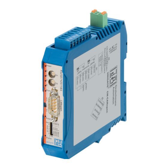
- Page 1 Instruction Manual Universal Fieldbus-Gateway ® UNIGATE CM - CANopen Deutschmann Automation GmbH & Co. KG www.deutschmann.com | wiki.deutschmann.de...
- Page 2 Manual Art.-No.: V4010E...
-
Page 3: Table Of Contents
Deutschmann Automation GmbH & Co. KG Information on CE marking of the module ....8 EU Directive EMC ......8 Scope of application . - Page 4 Deutschmann Automation GmbH & Co. KG Script processing times ......23 10 Hardware ports, switches and LEDs ....25 10.1 Device labeling .
- Page 5 Deutschmann Automation GmbH & Co. KG ® 16.4 Dimensional drawing UNIGATE CM - CANopen ... . 44 16.5 Commissioning ......45 16.6 Setting the CANopen address and baud rate .
- Page 6 Deutschmann Automation GmbH & Co. KG ® ® UNIGATE fieldbus gateway UNIGATE CM - CANopen V. 1.4 23.6.17...
- Page 7 We would be pleased to receive any improvement proposals which you may have. Copyright Copyright (C) Deutschmann Automation GmbH & Co. KG 1997 – 2017. All rights reserved. This document may not be passed on nor duplicated, nor may its contents be used or disclosed unless expressly permitted.
-
Page 8: Information On Ce Marking Of The Module
The EU Declarations of Conformity are available at the following location for perusal by the responsible authorities in accordance with the EU Directive, Article 10: Deutschmann Automation GmbH & Co. KG, Carl-Zeiss-Straße 8, 65520 Bad Camberg, Ger- many. Scope of application The modules are designed for use in the industrial sector and comply with the following requirements. -
Page 9: Information For The Machine Manufacturers
Deutschmann Automation GmbH & Co. KG Information for the machine manufacturers Information for the machine manufacturers Introduction ® The UNIGATE module does not constitute a machine as defined by the EU "Machinery“ Directive. Consequently, the module does not have a Declaration of Conformity in relation to the EU Machinery Directive. -
Page 10: Introduction
Introduction Deutschmann Automation GmbH & Co. KG Introduction ® The UNIGATE CM-CANopen module serves to adapt a serial port to CANopen. In this applica- tion, it functions as a Gateway and operates as CANopen Slave. It can be operated by any stan- dard-compliant Master. -
Page 11: Unigate ® Cm Software Flow-Chart
Deutschmann Automation GmbH & Co. KG Introduction ® UNIGATE CM software flow-chart ® ® 23.6.17 UNIGATE fieldbus gateway UNIGATE CM - CANopen V. 1.4... -
Page 12: Unigate ® Block Diagram
Introduction Deutschmann Automation GmbH & Co. KG ® UNIGATE block diagram ® The following picture shows a typical UNIGATE -module design. ® UNIGATE CM-application diagram The following graph shows a typical connection scheme. ® ® UNIGATE fieldbus gateway UNIGATE CM - CANopen V. 1.4... -
Page 13: Operation Modes Of The Gateway
Deutschmann Automation GmbH & Co. KG Operation modes of the Gateway Operation modes of the Gateway Configuration mode (config mode) The configuration mode serves to configure the Gateway. The following adjustments are possible in this mode. • Loading a Script •... -
Page 14: Data Exchange Mode
Operation modes of the Gateway Deutschmann Automation GmbH & Co. KG 4 Bytes are output on the additional CANopen interface (application side): 1 byte: Echo of the first received byte via CAN 2 byte: Read back byte IO8 3. byte: value of the DIP-switch (currently not used, fixed value is "FF") 4. -
Page 15: Rs-Interface
Deutschmann Automation GmbH & Co. KG RS-interface RS-interface ® RS-interfaces at the UNIGATE ® The UNIGATE CM - CANopen has the interfaces RS232, RS422 and RS485 available. The hardware always features a DEBUG-interface, see chapter 7. ® Buffer sizes at the UNIGATE ®... -
Page 16: Ssi-Interface
SSI-interface Deutschmann Automation GmbH & Co. KG SSI-interface ® The UNIGATE also supports the connection of applications or products, that communicate via SSI. Initiation of the SSI-interface The required Script (example_SSI), the firmware- (Cust0023) and PROTOCOL DEVEL- PER-extension (Cust_ssi.xml) are available free of charge from our website at www.deutschmann.de, as well as the softwaretool Protocol Developer and the configuration soft-... -
Page 17: Hardware-Wiring
(example CL-PB): Special Firmware (23) not loaded RS-PBV1-CL (232/422/485) V7.31[30] (c)dA Switch=0x02FF Script(8k)="SSI" Author="Deutschmann Automation" Version="V 1.0" Date=20.03.2008 SN=47110002 ID=2 Konfigmode... The note "Special Firmware (23) not loaded" means that the firmware-extension is not yet loaded. -
Page 18: The Debug-Interface
The Debug-interface Deutschmann Automation GmbH & Co. KG The Debug-interface Overview of the Debug-interface ® The UNIGATE IC features a Debug-interface, that allows a step-by-step processing of a Script. Normally this interface is only required for the development of a Script. -
Page 19: Mode Of Operation Of The System
Communication can be split into seven layers, Layer 1 to Layer 7, in accordance with the ISO/OSI model. The Deutschmann Automation Gateways convert Layers 1 and 2 of the customized bus system (RS485 / RS232 / RS422) to the corresponding Fieldbus system. Layers 3 to 6 are blank, and Layer 7 is converted in accordance with chapter 8.3. -
Page 20: Possible Data Lengths
Mode of operation of the system Deutschmann Automation GmbH & Co. KG Possible data lengths The table below shows the maximum transferable data in CANopen: Input data max. 255 bytes Variable: maximum value in this case Output data max. 255 bytes... -
Page 21: Generating A Script
Deutschmann Automation GmbH & Co. KG Generating a Script Generating a Script Note: All commands relating to the extension do not work in the debug mode! What is a Script? A Script is a sequence of commands, that are executed in that exact order. Because of the fact that also mechanisms are given that control the program flow in the Script it is also possible to assemble more complex processes from these simple commands. -
Page 22: Further Settings At The Gateway
Generating a Script Deutschmann Automation GmbH & Co. KG Further settings at the Gateway Most devices require no further adjustments, except for those made in the Script itself. However, there are also exceptions to it. These settings are made by means of the software WINGATE. If ®... -
Page 23: Script Processing Times
Deutschmann Automation GmbH & Co. KG Generating a Script I. e.: The baud rate actually adjusted by the Gateway is 9615.38 baud The resulting error in per cent can be calculated as follows: Error[%] = (abs(BaudIst - BaudSoll) / BaudSoll) * 100 In our example the following error results: Error = (abs(9615.38 - 9600) / 9600) * 100 = 0.16%... - Page 24 Generating a Script Deutschmann Automation GmbH & Co. KG By means of the tasks mentioned above, the following recommendation can be formulated in order to receive a rather fast Script processing: • Deactivate the Debug-interface (it is the normal case in the serial use) •...
-
Page 25: Hardware Ports, Switches And Leds
Deutschmann Automation GmbH & Co. KG Hardware ports, switches and LEDs 10 Hardware ports, switches and LEDs 10.1 Device labeling Picture 1: Terminal labeling and termination Picture 2: Front panel: Rotary switches, DIP-switch, LEDs and termination CO In case the front panel should pop out it does not affect the device’s function or quality. -
Page 26: Connectors
Hardware ports, switches and LEDs Deutschmann Automation GmbH & Co. KG 10.2 Connectors 10.2.1 Connector to the external device (RS-interface) The serial interface is available at the plug accessible on the upper side of the device. Pin assignment X1 (3-pole and 4-pole screw-type plug connector) Pin No. -
Page 27: Canopen-Connector
Deutschmann Automation GmbH & Co. KG Hardware ports, switches and LEDs 10.2.4 CANopen-connector The plug (labeled: CANopen) for the connection to CANopen is available on the front side of the device. Pin assignment (9-pin D-SUB, plug) Pin No. Name Function... -
Page 28: Led "Power / State
Hardware ports, switches and LEDs Deutschmann Automation GmbH & Co. KG LED triple flash a sequence of three short flashes (approximately 200ms), separated by an off phase (approximately 200ms). The sequence is finished by a long off phase (approximately 1000 ms). -
Page 29: Led "State
Deutschmann Automation GmbH & Co. KG Hardware ports, switches and LEDs More conditions in Configuration-, Test- or Update-Mode ® green/red flashing UNIGATE is in test mode ® red flashing UNIGATE is in configuration mode / error (see error table chapter 13.1.1) red bright CL basis stopped, PC connection with Ext.-Board active (Firmware update) -
Page 30: Rotary Coding Switches S4 + S5 (Serial Interface)
Hardware ports, switches and LEDs Deutschmann Automation GmbH & Co. KG 10.4.2 Rotary coding switches S4 + S5 (serial interface) These two switches can be read out through the Script command "Get (RS_Switch, Destination)" and the value can be used for further functions. This value is read in when the Gateway is switched on or always after a Script command has been executed. -
Page 31: Canopen Termination (Application Side)
Deutschmann Automation GmbH & Co. KG Hardware ports, switches and LEDs 10.4.4 CANopen termination (application side) If the Gateway is operated as the first or last physical device in the CANopen, there must be a bus termination at this Gateway. In order to do this, either a bus terminating resistor must be acti- vated in the connector or the resistor (120 ) integrated in the Gateway must be activated. -
Page 32: Error Handling
Error handling Deutschmann Automation GmbH & Co. KG 11 Error handling ® 11.1 Error handling at UNIGATE If the Gateway detects an error, the error is signalled by the “State“ LED lighting red and, simulta- neously, the error number being indicated by means of LEDs “Error No.“ as shown in the table below. -
Page 33: Error On The Cl-Extension
Deutschmann Automation GmbH & Co. KG Error handling 11.1.1 Error on the extension An error on the extension will be signaled through red flashing of the Power/State-LED. The LED of the according error number turns off. This is followed by a short, then the flashing sequence is repeated. -
Page 34: Installation Guidelines
Installation guidelines Deutschmann Automation GmbH & Co. KG 12 Installation guidelines 12.1 Installation of the module The module with the dimensions 23 x 117 x 117 mm (W x D x H) has been developed for switch cabinet use (IP 20) and can thus be mounted only on a standard mounting channel (deep DIN-rail to EN 50022). -
Page 35: Canopen Communication Interface
Deutschmann Automation GmbH & Co. KG Installation guidelines 12.2.1.1 Power supply The device must be powered with 10..33 V DC. • Connect the supply voltage to the 4-pole plug-in screw terminal in accordance with the labelling on the device. 12.2.1.2 Equipotential bonding connection The connection to the potential equalization automatically takes place it is put on the DIN-rail. - Page 36 Installation guidelines Deutschmann Automation GmbH & Co. KG The table below allows you to read off the conditions for laying the line groups on the basis of the combination of the individual groups. Group A Group B Group C Group A...
- Page 37 Deutschmann Automation GmbH & Co. KG Installation guidelines • Use metal cable clips to secure the shield braiding. The clips must surround the shield over a large area and must have good contact. • Downstream of the entry point of the line into the cabinet, connect the shield to a shielding bus.
-
Page 38: Firmware Cl-Extension With Canopen Interface
Firmware CL-extension with CANopen interface Deutschmann Automation GmbH & Co. KG 13 Firmware CL-extension with CANopen interface The firmware version is output in the configuration mode (see chapter 4.1). The actual start-up message appears, following the message of the extension that looks similar to the following: Ext-Board: CL-Erweiterung(CANopen-IO-DICNET) V0.74 (c)dA SN=4294967295... -
Page 39: Canopen
Deutschmann Automation GmbH & Co. KG CANopen 14 CANopen 14.1 Description CANopen ® This specification is based on the CiA Draft Standard 301 (DS301). CANopen supports the Standard CAN-frame with 11-bit Identifier. It is not required to support the extended frame with 29-bit Identifier. - Page 40 CANopen Deutschmann Automation GmbH & Co. KG Use the following values for the parameters: CAN Layer 2 If you want to use CAN Layer 2, you can set a special Script initialization to access every CAN message without any Filter. Please note that the data format for ReadBus and WriteBus differs from other functionalities in this case.
-
Page 41: Canopen V4
Deutschmann Automation GmbH & Co. KG CANopen 14.1.2 CANopen V4 Additional supported functions: • Heartbeat • Dynamic mapping • Onswich message The following example can be found in the file folder “example“ after the installation of the soft- ware “Protocol Developer“ (this example gives a detailed description of the initialization): •... -
Page 42: Technical Data
Technical data Deutschmann Automation GmbH & Co. KG 15 Technical data 15.1 Device data The technical data of the module is given in the table below. No. Parameter Data Explanations Location Switch cabinet DIN-rail mounting Enclosure IP20 Protection against foreign bodies... -
Page 43: Interface Data
Deutschmann Automation GmbH & Co. KG Technical data 15.1.1 Interface data The table below lists the technical data of the interfaces and ports on the device. The data has been taken from the corresponding Standards. Interface designation CANopen RS232-C RS485/RS422 No. -
Page 44: Commissioning Guide
Commissioning guide Deutschmann Automation GmbH & Co. KG 16 Commissioning guide 16.1 Note ® Only trained personnel following the safety regulations may commission the UNIGATE 16.2 Components ® You will require the following components to commission the UNIGATE ® •... - Page 45 Deutschmann Automation GmbH & Co. KG Commissioning guide 16.5 Commissioning It is essential that you perform the following steps during commissioning in order to ensure that the module operates correctly: 16.6 Setting the CANopen address and baud rate Set the CANopen-Node-ID and the baud rate at the fieldbus end of the module on the DIP-switch (see chapter 10.4.5).
- Page 46 Commissioning guide Deutschmann Automation GmbH & Co. KG If the required EDS file was not supplied with your project planning tool, a sample file can be found on the Internet (www.deutschmann.de). ® ® UNIGATE fieldbus gateway UNIGATE CM - CANopen V. 1.4...
- Page 47 Deutschmann Automation GmbH & Co. KG Servicing 17 Servicing Should questions arise that are not covered in this manual you can find further information in our • FAQ/Wiki area on our homepage www.deutschmann.com or directly in our Wiki on www.wiki.deutschmann.de If your questions are still unanswered please contact us directly.
- Page 48 Annex Deutschmann Automation GmbH & Co. KG 18 Annex 18.1 Explanations of the abbreviations General Product group CL (Compact Line) Product group CM (CANopen Line) Product group CX Product group EL (Ethernet Line) Product group FC (Fast Connect) Galvanic separation RS-side...
- Page 49 Deutschmann Automation GmbH & Co. KG Annex Profinet-IO PBDP ProfibusDP ® PBDPL ProfibusDP-version L (see comparison table UNIGATE IC for the respective product) ® PBDPX ProfibusDP-version X (see comparison table UNIGATE IC for the respective product) PBDPV0 = ProfibusDPV0 PBDPV1 =...
Need help?
Do you have a question about the UNIGATE CM-CANopen and is the answer not in the manual?
Questions and answers