
Related Manuals for DEUTSCHMANN AUTOMATION UNIGATE CM - PROFIBUS


Summary of Contents for DEUTSCHMANN AUTOMATION UNIGATE CM - PROFIBUS
- Page 1 Instruction Manual Universal Fieldbus-Gateway ® UNIGATE CM - PROFIBUS Deutschmann Automation GmbH & Co. KG www.deutschmann.com | wiki.deutschmann.de...
- Page 2 Manual Art.-Nr.: V4009E...
-
Page 3: Table Of Contents
Deutschmann Automation GmbH & Co. KG Information on CE marking of the module ....8 EU Directive EMC ......8 Scope of application . - Page 4 Deutschmann Automation GmbH & Co. KG 9.2.1 Connector to the external device (RS-interface) ....22 9.2.2 Connector supply voltage and DEBUG-interface ....23 9.2.3 CANopen interface connector .
- Page 5 Deutschmann Automation GmbH & Co. KG ® 14 Implemented protocols in UNIGATE CM ....39 14.1 Implemented protocols (Transport protocols at the CM interface) ..39 14.2 Configuration options for the individual transport protocol .
- Page 6 Deutschmann Automation GmbH & Co. KG 16.12 Shield connection ......58 16.13 Project planning ......58 16.14 Literature .
- Page 7 We would be pleased to receive any improvement proposals which you may have. Copyright Copyright (C) Deutschmann Automation GmbH & Co. KG 1997 – 2017. All rights reserved. This document may not be passed on nor duplicated, nor may its contents be used or disclosed unless expressly permitted.
-
Page 8: Information On Ce Marking Of The Module
The EU Declarations of Conformity are available at the following location for perusal by the responsible authorities in accordance with the EU Directive, Article 10: Deutschmann Automation GmbH & Co. KG, Carl-Zeiss-Straße 8, 65520 Bad Camberg, Ger- many. Scope of application The modules are designed for use in the industrial sector and comply with the following requirements. -
Page 9: Information For The Machine Manufacturers
Deutschmann Automation GmbH & Co. KG Information for the machine manufacturers Information for the machine manufacturers Introduction ® The UNIGATE module does not constitute a machine as defined by the EU "Machinery“ Directive. Consequently, the module does not have a Declaration of Conformity in relation to the EU Machinery Directive. -
Page 10: Introduction
Introduction Deutschmann Automation GmbH & Co. KG Introduction ® The UNIGATE CM-PROFIBUS DP module serves to adapt a CANopen interface to PROFIBUS according to EN 50 170. In this application, it functions as a Gateway and operates as the PROFIBUS DP Slave. It can be operated by any standard-compliant PROFIBUS Master. -
Page 11: Unigate ® Cm Software Flow-Chart
Deutschmann Automation GmbH & Co. KG Introduction ® UNIGATE CM software flow-chart ® ® 23.6.17 UNIGATE Feldbus-Gateway UNIGATE CM - PROFIBUS V. 1.6... -
Page 12: Unigate ® Block Diagram
Introduction Deutschmann Automation GmbH & Co. KG ® UNIGATE block diagram ® The following picture shows a typical UNIGATE -module design. ® UNIGATE CM application diagram The following graph shows a typical connection scheme. ® ® UNIGATE Feldbus-Gateway UNIGATE CM - PROFIBUS V. 1.6... -
Page 13: Operation Modes Of The Gateway
Deutschmann Automation GmbH & Co. KG Operation modes of the Gateway Operation modes of the Gateway Configuration mode (config mode) The configuration mode serves to configure the Gateway. The following adjustments are possible in this mode. • Loading a Script •... -
Page 14: Data Exchange Mode
Operation modes of the Gateway Deutschmann Automation GmbH & Co. KG Data exchange mode The Gateway has to be in the data exchange mode, so that a data exchange between the CANopen-side of the Gateway and the Fieldbus is possible. As long as the Gateway is not in the configuration-, test-, firmware-update-, or debug mode, the data exchange mode is active. -
Page 15: Rs-Interface
Deutschmann Automation GmbH & Co. KG RS-interface RS-interface ® RS-interfaces at the UNIGATE ® The UNIGATE CM - PROFIBUS DP has the interfaces RS232, RS422 and RS485 available. The hardware always features a DEBUG-interface, see chapter 6. ® Buffer sizes at the UNIGATE ®... -
Page 16: The Debug-Interface
The Debug-interface Deutschmann Automation GmbH & Co. KG The Debug-interface Overview of the Debug-interface ® The UNIGATE features a Debug-interface, that allows a step-by-step processing of a Script. Normally this interface is only required for the development of a Script. - Page 17 Deutschmann Automation GmbH & Co. KG The Debug-interface If debugging is redirected to the application, no script or command that wants to carry out com- munication via the application interface is supported. These are e.g.: SendRS and ReceiveSomeCharRS. ® ®...
-
Page 18: Mode Of Operation Of The System
Communication can be split into seven layers, Layer 1 to Layer 7, in accordance with the ISO/ OSI model. The Deutschmann Automation Gateways convert Layers 1 and 2 of the customized bus system (RS485 / RS232 / RS422) to the corresponding Fieldbus system. Layers 3 to 6 are blank, and Layer 7 is converted in accordance with chapter 7.3. -
Page 19: Generating A Script
Deutschmann Automation GmbH & Co. KG Generating a Script Generating a Script Note: All commands relating to the extension do not work in the debug mode! See chapter 6.5. What is a Script? A Script is a sequence of commands, that are executed in that exact order. Because of the fact that also mechanisms are given that control the program flow in the Script it is also possible to assemble more complex processes from these simple commands. -
Page 20: The Use Of The Protocol Developer
Generating a Script Deutschmann Automation GmbH & Co. KG have to be known as fixed values and are not available for the runtime. Another reason for the configuration of the values in WINGATE is the following: After an update of the Script these val- ues remain untouched, i. -
Page 21: Script Processing Times
Deutschmann Automation GmbH & Co. KG Generating a Script In the following please find a listing of baud rates at a 40 MHz-crystal frequency with the corre- sponding errors: 4800 baud: 0.16% 9600 baud:0.16% 19200 baud:0.16% 38400 baud:1.35% 57600 baud:1.35% 62500 baud:0% 115200 baud:1.35%... -
Page 22: Hardware Ports, Switches And Leds
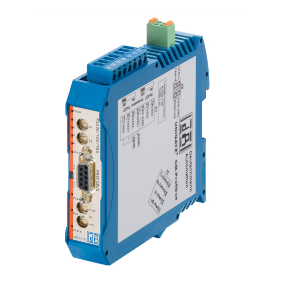
Hardware ports, switches and LEDs Deutschmann Automation GmbH & Co. KG Hardware ports, switches and LEDs Device labeling Picture 1: Terminal labeling and termination Picture 2: Front panel: Rotary switches, LEDs and termination PB In case the front panel should pop out it does not affect the device’s function or quality. -
Page 23: Connector Supply Voltage And Debug-Interface
Deutschmann Automation GmbH & Co. KG Hardware ports, switches and LEDs For the operation at a 485-interface the two pins labeled "485-" have to be connected together. Also the two pins "485+". 9.2.2 Connector supply voltage and DEBUG-interface Pin assignment X2 (4-pole screw-plug connector, on the bottom side, at the back) Pin No. -
Page 24: Leds
Hardware ports, switches and LEDs Deutschmann Automation GmbH & Co. KG LEDs ® The Gateway UNIGATE CM - PROFIBUS features 9 LEDs with the following significance: LED Power/State red/green Interface state Ethernet LEDs 1 / 2 / 4 / 8 (Error No. / Select ID) green... -
Page 25: Leds 1 / 2 / 4 / 8 (Error No. / Select Id)
Deutschmann Automation GmbH & Co. KG Hardware ports, switches and LEDs Triple flash Sync Error The SYNC message has not been received within the configured communication cycle period time out (see Object Dictionary Entry 0x1006). Bus Off The CAN controller is’bus off If at a given time several errors are present, the error with the highest number is indicated (e.g. -
Page 26: Led "Bus State
Hardware ports, switches and LEDs Deutschmann Automation GmbH & Co. KG 9.3.6 LED "Bus State" Lights green PROFIBUS in the state data exchange Flashes green Gateway waits for PROFIBUS communication data Flashes green/red Gateway waits for PROFIBUS parameter data Lights red... -
Page 27: Termination (Profibus)
Deutschmann Automation GmbH & Co. KG Hardware ports, switches and LEDs Switch positions Switch Switch postions postions Function Description Firmware- Update Ext.- (Description see chapter 12) Board (Description see chapter 4.2) Test mode Note: This mode can only be terminated by a reboot. -
Page 28: Error Handling
Error handling Deutschmann Automation GmbH & Co. KG 10 Error handling ® 10.1 Error handling at UNIGATE If the Gateway detects an error, the error is signalled by the “State“ LED lighting red and, simulta- neously, the error number being indicated by means of LEDs “Error No.“ as shown in the table below. -
Page 29: Error On The Extension
Deutschmann Automation GmbH & Co. KG Error handling A detailed error diagnosis can be recorded with an activated "Diagnosis Monitor" via the applica- tion interface. For this you only need to connect/start a RS232 Monitor tool, such as Deutschmann Starterkit tool "RS232 module" via a PC. (9600/1/8/N). -
Page 30: Installation Guidelines
Installation guidelines Deutschmann Automation GmbH & Co. KG 11 Installation guidelines 11.1 Installation of the module The module with the dimensions 23 x 117 x 117 mm (W x D x H) has been developed for switch cabinet use (IP 20) and can thus be mounted only on a standard mounting channel (deep DIN- rail to EN 50022). -
Page 31: Equipotential Bonding Connection
Deutschmann Automation GmbH & Co. KG Installation guidelines 11.2.1.2 Equipotential bonding connection The connection to the potential equalization automatically takes place it is put on the DIN-rail. 11.2.2 PROFIBUS DP communication interface 11.2.2.1 Bus line with copper cable This interface is located on the module in the form of a 9-pin D-SUB socket on the front side of the housing. -
Page 32: Shielding Of Lines
Installation guidelines Deutschmann Automation GmbH & Co. KG 11.2.4.1 Shielding of lines Shielding is intended to weaken (attenuate) magnetic, electrical or electromagnetic interference fields. Interference currents on cable shields are discharged to earth via the shielding bus which is con- nected conductively to the chassis or housing. -
Page 33: Firmware Update
Deutschmann Automation GmbH & Co. KG Firmware Update 12 Firmware Update ® The UNIGATE CM consists of a basic hardware and an ext. board. The firmware versions are output in the configuration mode (see Chapter 4.1). The start-up message of the basic appears, following the message of the ext. -
Page 34: Profibus Dp
PROFIBUS DP Deutschmann Automation GmbH & Co. KG 13 PROFIBUS DP 13.1 Description of the DPV1-/DPV2-functions 13.1.1 DPV1 Die DPV1-Erweiterung besteht aus folgenden Funktionen: 1. Acyclic data exchange with Class1-Master (e. g.: PLC) This function is optional for a DPV1-Slave. Our gateways support this function as a default. By means of this function the Class1-Master can read and write data from the slave acyclically. -
Page 35: Configuration Telegram
Deutschmann Automation GmbH & Co. KG PROFIBUS DP After programming, the Master must send a configuration telegram to the corresponding Slave. The configuration telegram provides the Slave with information on the length of the input/output data. If the user has set the ’Length byte’ flag, this means the maximum data lengths. Otherwise, it means the actual lengths. - Page 36 PROFIBUS DP Deutschmann Automation GmbH & Co. KG The diagnostic information of a DP Slave consists of standard diagnostic information items (6 bytes) and a user-specific diagnostic information item. (Error number) Telegram for diagnostic request: Octet 10 Diag.station does not exist (sets Master) Diag.station not_ready: Slave is not ready for...
-
Page 37: Diagnosis In Dpv1
Deutschmann Automation GmbH & Co. KG PROFIBUS DP Octet 30 reserved Diag.ext_overflow Octet 40 Diag master_add: Master address after programming (FF without programming) Octet 50 Ident. number high byte Octet 60 Ident. number low byte Octet 70 External diagnosis: header, length entry... -
Page 38: Data Exchange
PROFIBUS DP Deutschmann Automation GmbH & Co. KG 13.2.4 Data exchange After the Master, in the diagnostic, detects that the Slave is ready for data exchange, it sends data exchange telegrams. Either the Master stores the data in the input/output direction in the address area specified during project planning or the control program must fetch or retrieve the data using specific function blocks. -
Page 39: Implemented Protocols In Unigate ® Cm
Deutschmann Automation GmbH & Co. KG Implemented protocols in UNIGATE® CM ® 14 Implemented protocols in UNIGATE ® On delivery the UNIGATE CM is supplied with the Script “Universalscript Deutschmann CM“. The configuration is carried out in the configuration mode (see chapter 4.1) with the software WINGATE from Version V2.85 and wcf-file from 406. -
Page 40: Configuration Options For The Individual Transport Protocol
Implemented protocols in UNIGATE® CM Deutschmann Automation GmbH & Co. KG 14.2 Configuration options for the individual transport protocol 14.2.1 Possibilities on the CANopen side (CM) Universal Universal Universal L2 11Bit Transport CANopen Layer 2 Universal (L2 11/ (L2 11Bit) -
Page 41: Operation Of The Transport Protocols
Data structure ® The Gateway can be configured through the software WINGATE that is also supplied. This Gateway module from the UNIGATE range of Deutschmann Automation allows a coupling between PROFIBUS DP and CANopen ® ® Here the Gateway on the CANopen... -
Page 42: Node Guarding
Implemented protocols in UNIGATE® CM Deutschmann Automation GmbH & Co. KG Now the Mappings can be changed, deleted or new ones can be added. Alternatively, the values can also be entered in the right table. The entry must be confirmed with "Apply", only then the values are taken. -
Page 43: Displaying The Node Guarding States
Deutschmann Automation GmbH & Co. KG Implemented protocols in UNIGATE® CM If the slave receives no node guard inquiry it assumes that the bus connection is broken or the master went down. Settings As presetting it applies tfor all slaves that no node guarding is carried out. Shall that node guar- ding be activated for a slave, an entry "enable node guarding"... -
Page 44: Emergency Messages
Implemented protocols in UNIGATE® CM Deutschmann Automation GmbH & Co. KG Example: For node 1 and 2 node guarding is activated. Slave 1 doesn not answer to the node guarding and slave ID 2 works regularly. A mapping of information is entered into the PROFIBUS in the 2nd byte. -
Page 45: Bit 7 (Msb): Emcy Toggle Bit
Deutschmann Automation GmbH & Co. KG Implemented protocols in UNIGATE® CM 14.3.1.6 Bit 7 (MSB): EMCY toggle bit With this bit the next relevant EMCY message can be transfered to the current data buffer, no matter whether the data is shown in the fieldbus or not. The counter is lowered by 1, provided that it does not equal 0. - Page 46 Implemented protocols in UNIGATE® CM Deutschmann Automation GmbH & Co. KG Data record structure (FB-input = data from the FB-Master): Data record structure (FB-output = data to the FB-Master): Example: In this example the PB-Idx (In) and PB-Idx (Out) equal 8 Please note: The counting starts at index "0"...
-
Page 47: Slave Mode
Deutschmann Automation GmbH & Co. KG Implemented protocols in UNIGATE® CM Data Len(data length = 2) Data Len(data length = 2) Data... Data... (47h = hardw.vers. „G“) 17. byte 17. byte 14.3.1.11 Slave mode ® The Slave mode can be activated through WINGATE . -
Page 48: Starting Phase
Implemented protocols in UNIGATE® CM Deutschmann Automation GmbH & Co. KG 14.3.1.14 Starting phase ® During the starting phase the UNIGATE sends the NMT-command "BusStart" every 2 seconds, ® that means all connected CANopen -Slaves are set into the condition "Operational". -
Page 49: Universal (L2 11Bit)
Deutschmann Automation GmbH & Co. KG Implemented protocols in UNIGATE® CM Data structure Data mapping on the fielbus: Example: 01 81 11 22 33 44 55 66 77 88 00 00 00 01 81 A1 A2 A3 A4 A5 A6 A7 A8 00 00 00 ... -
Page 50: Universal (L2 11Bit) With Cob-Id Used
Implemented protocols in UNIGATE® CM Deutschmann Automation GmbH & Co. KG Identical with protocol "Layer 2 11Bit" (see chapter 14.3.2) However there are additional configu- rations possible on the fieldbus side: Fieldbus trigger byte (i.e. fieldbus data exchange = On Trigger), fieldbus length byte and swap word. - Page 51 Deutschmann Automation GmbH & Co. KG Implemented protocols in UNIGATE® CM 1. Byte number of received data from CAN (Low Nibble) MSB = 0 => 11Bit Frame received 2. Byte not used 3. Byte not used 4. Byte COB-ID High Byte 5.
-
Page 52: Universal (L2 11/29Bit) With Cob-Id Used
Implemented protocols in UNIGATE® CM Deutschmann Automation GmbH & Co. KG 14.3.6 Universal (L2 11/29Bit) with COB-ID used Identical with protocol Universal (L2 11/29Bit), see chapter 14.3.5, with additional configuration possibility. Up to 16 COB-ID’s can be configured to which the CAN interface can react to as described in chapter 14.3.4. -
Page 53: Technical Data
Deutschmann Automation GmbH & Co. KG Technical data 15 Technical data 15.1 Device data The technical data of the module is given in the table below. No. Parameter Data Explanations Location Switch cabinet DIN-rail mounting Enclosure IP20 Protection against foreign bodies... -
Page 54: Interface Data
Technical data Deutschmann Automation GmbH & Co. KG 15.1.1 Interface data The table below lists the technical data of the interfaces and ports on the device. The data has been taken from the corresponding Standards. Interface designation ProfibusDP RS232-C RS485/RS422 ®... - Page 55 Deutschmann Automation GmbH & Co. KG Technical data Transmit range (SPACE): - Voltage level - 0.2 ... + 0.2 V + 3 ... + 15 V - 0.2 ... + 0.2 V - 0.5 ... + 0.05 V - Logic level...
-
Page 56: Commissioning Guide
Commissioning guide Deutschmann Automation GmbH & Co. KG 16 Commissioning guide 16.1 Note ® Only trained personnel following the safety regulations may commission the UNIGATE 16.2 Components ® You will require the following components to commission the UNIGATE ® •... -
Page 57: Setting The Profibus Address
Deutschmann Automation GmbH & Co. KG Commissioning guide 16.6 Setting the PROFIBUS address Set the PROFIBUS address at the fieldbus end of the module on the two rotary switches desig- nated "PROFIBUS-ID High" and "PROFIBUS-ID Low" This adjustment is carried out in a hexa- decimal way. -
Page 58: Profibus Connection
Commissioning guide Deutschmann Automation GmbH & Co. KG Attention: The PROFIBUS address set must correspond to the planned address under COM PROFIBUS! It is read in only on power-up of the gateway! 16.7 PROFIBUS connection Connect the device to the Profibus at the interface labelled "PROFIBUS". -
Page 59: Servicing
Deutschmann Automation GmbH & Co. KG Servicing 17 Servicing Should questions arise that are not covered in this manual you can find further information in our • FAQ/Wiki area on our homepage www.deutschmann.com or directly in our Wiki on www.wiki.deutschmann.de If your questions are still unanswered please contact us directly. -
Page 60: Annex
Annex Deutschmann Automation GmbH & Co. KG 18 Annex 18.1 Explanations of the abbreviations General = Product group CL (Compact Line) = Product group CM (CANopen Line) = Product group CX = Product group EL (Ethernet Line) = Product group FC (Fast Connect) -
Page 61: Hexadecimal Table
Deutschmann Automation GmbH & Co. KG Annex = PROFINET-IO PBDP = PROFIBUS DP ® PBDPL = PROFIBUS DP-version L (see comparison table UNIGATE IC for the respective product) ® PBDPX = PROFIBUS DP-version X (see comparison table UNIGATE IC for the respective...
Need help?
Do you have a question about the UNIGATE CM - PROFIBUS and is the answer not in the manual?
Questions and answers