
Related Manuals for Sanyo Denki SANUPS E11A Series


Summary of Contents for Sanyo Denki SANUPS E11A Series
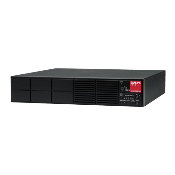
- Page 1 M0010662 Uninterruptible Power Supply 1kVA, 1.5kVA, 2kVA, 3kVA 100V Model Instruction Manual...
-
Page 2: Table Of Contents
§10. Load Devices Connection ..................Service technician This term is used to indicate service technicians from SANYO DENKI or entrusted from SANYO DENKI with knowledge of this UPS. Maintenance work must not be performed by other than a qualified service technician. - Page 3 Notes about UPS Model This manual is for the following UPS Models. Confirm your UPS Model before using the UPS. UL Model UPS Model name* Capacity Output Voltage E11A102U001-20 E11A102U 120V E11A102 1kVA E11A102U001-00 E11A102U-J 100V E11A152U001 E11A152U 120V E11A152 1.5kVA E11A152U001J E11A152U-J...
-
Page 4: Before Use
Before Use § § The procedures to use the UPS are shown in the following. Be sure to proceed as follows to use the UPS safely and properly. Check the safety precautions ⇒ pages 2 to 5 Check the usage precautions ⇒... -
Page 5: Safety Precautions
Safety Precautions § § PRECAUTIONS (IMPORTANT SAFETY INSTRUCTIONS) This Manual contains important instructions for operating and maintaining the E11A Series and the batteries to protect the safety of the service technician and the customers. Before installing, operating, performing maintenance or inspecting the UPS, be sure to read this manual and accompanying documents carefully to obtain a clear understanding of the information related to its operation, safety and important precautions. - Page 6 Safety Precautions 1. Relocation and Transportation Precautions CAUTION ! Be careful to avoid falling or dropping the UPS during relocation or transportation, as bodily injury could result. Be careful to avoid back strain when handling the UPS. To avoid bodily injury caused by dropping the UPS, do not tilt it more than 10 degrees to either side when moving the UPS vertically.
- Page 7 Safety Precautions 4. Operating Precautions WARNING Immediately shut the UPS off if it malfunctions, or if an unusual odor or noise is observed. Failure to do so may result in a fire. To avoid electric shock, do not open the cover of the UPS. Do not detach the cover of the options, except when you use some options.
- Page 8 SANYO DENKI. Do not use batteries after their service life has expired. Doing so may result in fuming or fire. Additionally, the battery backup function may fail to operate with such batteries, so that power will not supplied to the load when a power outage occurs.
-
Page 9: For Proper Operation
For Proper Operation § § § § (1) Input Power Requirements The input power of this UPS is shown in the following table. Adjust the output voltage of the UPS to match the AC input voltage* of the region where you are using the UPS. Recommended capacity AC input MODEL... -
Page 10: Usage Precautions
Conducting an insulation test with the UPS connected may damage electronic components such as the built-in arrester. (6) Rack support rails (not supplied) are required to mount the UPS on a rack. For details, contact your supplier or SANYO DENKI representative. -
Page 11: Checking The Contents Of The Package
After opening the package carton, check to be sure that it contains all of the following items. Are UPS and all accessories in ? Is there no visible damage on the UPS? □ Check and put the mark in If any item is missing, contact your supplier or SANYO DENKI. □ □ E11A □... -
Page 12: External Dimensions And Part Names
Part Names § § § § ⑫ (Inside cover) ① 440mm 17.32 inches ③ (Inside cover) ALARM INV. STAND BY B ATT. BATT. TEST CLEAR CLEAR ECONOMY ⑩ ⑧ ⑦ ⑥ ⑤ OUTPUT max.700W 8.3A MAIN SW INPUT EXT. BATT ④... - Page 13 In case of E11A202 or 302, the switch described as MAIN SW indicates MAIN MCCB breaker. *2. Contact your supplier or a SANYO DENKI representative for more information about optional equipment. Refer to the Instruction Manual of the optional equipment for details about installation procedures and specifications.
-
Page 14: Control Panel And Indicators
Part Names § § ⑥ ⑦ ⑧ ⑨ ⑪ ⑫ ⑬ ⑭ ⑤ ⑮ Indications of LED in this manual The LEDs on the control panel are described as “Green INPUT” or “Red ALARM”. The LEDs state are indicated as follows; ⑯... -
Page 15: External Interfaces
Part Names § § ① Rear view OUTPUT max.700W 10A MAIN SW INPUT EXT. EXT. BATT BATT ② Name Function Allows you to control the UPS from a computer (personal computer or workstation) PC I/F ① by using the supplied power management software. PC interface (RS-232C) Install the power management software on the computer, and connect the computer... -
Page 16: Installation
Installation § § When installing the UPS, carefully follow the instructions in Weight this Instruction Manual. Improper installation can result in Model electric shock, bodily injury, and/or fire. E11A102 37.5 Install the UPS on a stable surface that can bear the weight E11A152 48.5 (see the table). -
Page 17: Horizontal Installation
Installation § § Do not sit, step or lean on the UPS, as bodily injury could result if the UPS was to fall. The UPS weight is as shown in the table in §6. All work that involves lifting the UPS !... - Page 18 Installation § § Attach the stands to the UPS securely. Unless the UPS is secured solidly in place, it can shift or fall during seismic events (earthquakes) or when it is subjected to shock or vibration, possibly causing bodily injury. !...
-
Page 19: Vertical Installation
Installation ① Prepare two floor mounting brackets, four screws , and four bushings supplied. ※ Floor mounting brackets 2 Bushings 4 Screws for brackets M4×6 4 ※ Use the “Screws for rack mounting brackets” to attach the floor mounting brackets on the UPS. ②... -
Page 20: Rack Mounting
Installation § § Attach the rack mounting brackets to the UPS and mount it to the rack securely. Unless the UPS is secured in the rack, it can shift or fall during seismic events (earthquakes) or when it is subjected to shock or vibration, possibly causing bodily injury. The UPS weight is as shown in the table in §6. -
Page 21: Wiring
Wiring § § § § Wear insulated gloves and take other precautions when connecting the batteries. Otherwise electric shock can result. There is a constant voltage (refer to the table) at the battery s Model Voltage (max.) terminals. Do not touch them with your hands or short !... -
Page 22: Input Plug Connection
Wiring § § Wiring should be performed only by technically qualified personnel. Incorrect wiring can result in electric shock and/or fire. Check that the input power plugs are firmly seated. ! Failure to do so can result in electric shock, fire, or bodily injury. The input power plug must be grounded. - Page 23 Wiring Note When the AC input power is single-wire grounded, always connect the ground phase to the W terminal (S phase) side on the UPS. ② To 3-prong grounded utility power outlet. Length: 1.8 m Adaptable outlet: NEMA 5-20R (71 inches) is “OFF”.
-
Page 24: Procedure Until Load Device Operation
Procedure Outline to Operation § § The procedure outline until turning on the load devices is as follows. Be sure to follow the procedure outline below to backup the load devices during power outage. Check the default value of the user setting ⇒... -
Page 25: Preparation Before Operation
Preparation Before Operation § § § § ① Check the user settings of the UPS. See §12.2 “Setup Menu List” to check the setting value. The factory default settings of the UPS are indicated by the “ * ” mark in the “Default Setting” column in the “Setup Menu List”. When the load specification, requirement or your When you use the UPS without changing environments do not configurate with the default... -
Page 26: Ups Charge
MAIN MCCB 1 again. If the alarm buzzer sounds again, contact steps 1 to 3 described in §7.2 “Input Plug your supplier or SANYO DENKI representative. Connection” again. ③ Check that the “Green INPUT” stops blinking and remains lit. Charging of the UPS starts automatically. -
Page 27: Outage Simulation Test
Preparation Before Operation § § Perform a power outage test to confirm whether the UPS is working properly. Be sure to perform this test prior to connecting the load devices. Step ① is not necessary if the procedure in §9.2 “UPS Charge” was performed beforehand. - Page 28 “Red ALARM” lights. Contact your supplier. Contact your supplier or SANYO DENKI when the “Red ALARM” lights or when the UPS does not operate properly even if you perform the countermeasure above. Check that the UPS operates properly, and then proceed to step ⑤.
-
Page 29: Load Devices Connection
Load devices connection § § Connect the load devices. “OFF” Breaker is OUTPUT max.700W 10A ① Check that MAIN SW is set to “OFF”. MAIN SW ② Connect the input power plugs of the load devices to the output INPUT terminals. -
Page 30: Operating Procedures
Operating Procedures § § § § Indications of Switch and LED in this manual. The switches or breakers are indicated by a frame Example: MAIN SW . The LEDs on the control panel are described as Proceed as follows to start up the UPS. “Green INPUT”... - Page 31 Operating Procedures At this step, turn the load device power on. LEDs Green INPUT Green INV.ON/STAND BY Green OUTPUT Green LOADLEVEL 25 -100% Lit Green DOUBLE CONVERSION Lit After “Green DOUBLE CONVERSION” lights, it might go off depending on the input power condition or the load device condition.
-
Page 32: Ups Shutdown (Daily)
Operating Procedures § § Perform the following operation to shut down the UPS daily. Be sure to shut down the load devices prior to shutting down the UPS. ① Press and hold for at least 1 second. Buzzer Musical trill LEDs Green INPUT Hold for 1 second.*... -
Page 33: Ups Shutdown (If Not To Be Used For More Than A Week)
Operating Procedures § § Perform the following operation if the UPS is not to be used for at least a week. Be sure to shut down the load devices prior to shutting down the UPS. ① Press and hold for at least 1 second. Buzzer Musical trill LEDs... -
Page 34: User Settings
User setting § § § § The UPS has a user settings menu, described in §12.2 “Setup Menu List”. The factory default setting of the UPS is indicated by the “ * ” mark in the “Default Setting” column. You can set the various menu items to configure the UPS according to your environment, your applications, and the specifications of the connected load devices. -
Page 35: Setup Menu List
User setting § § ●: indicates that LED is blinking. ○: indicates that LED is off. User Settings Setting Default Current Guide Menu Menu LED Setting Remarks Setting Setting Ref. page Item Auto Switch the UPS operating mode automatically. ●○○○ ○... -
Page 36: Maintenance
Deal with a trouble or failure in the UPS. * What are service personnel? This term is used to indicate service technicians from SANYO DENKI or entrusted from SANYO DENKI with knowledge of this UPS. Maintenance work must not be performed by other than a qualified service technician. -
Page 37: Routine Checks
Maintenance § § Be sure not to inspect the inside of the UPS. Doing so may result in an electric shock, burn, injury, smoke, or fire. Do not touch the fan on the back panel of the UPS when cleaning the !... -
Page 38: Battery Test
Replacing the battery early is recommended. Result are OK. Contact SANYO DENKI. ② After the battery test has finished and the “Green BATT. TEST” indicator lights or blinking, press The “Green BATT. TEST” indicator goes off and returns to its normal indication. -
Page 39: Bypass Breaker Reset
Maintenance § § Always power the UPS off before resetting the bypass breaker. ! Failure to do so can cause electric shock. CAUTION If the bypass breaker trips, the red ALARM indicator lights and output from the output terminals stops. Proceed as follows to reset the bypass breaker. -
Page 40: Maintenance By Service Personnel
Maintenance § § The user must not perform the maintenance described in this section. Be sure to contact your supplier for maintenance. § § Batteries should be replaced periodically. Batteries used after their service life has passed may cause a fire. Never use organic chemicals such as gasoline, thinner, benzene or detergent to clean batteries. - Page 41 Maintenance ⑦ Insert the new battery pack so that the connector faces forward. ⑧ Connect the battery connector. ⑨ Set the ⑨ Set the to “Inverter”. Forced Bypass Forced Bypass switch to “Inverter” position. ⑩ Check that “Green OUTPUT” and “Green INV.ON/STANDBY” are blinking, then press and hold for at least 1 second.
-
Page 42: Buzzer Sounds
Buzzer Sounds § § The buzzer sounds to indicate an UPS status error or change. Press to stop the buzzer. Check the sound pattern and refer to the following table for the steps to take. Sound Pattern LED Status UPS Status What to Do This is a mechanical Red ALARM lit... -
Page 43: Troubleshooting
Troubleshooting § § Internal maintenance and inspection should be performed only by technically qualified personnel. Electric shock, injury, burning, fuming or fire could otherwise result. ! Before beginning inspection, shut down the UPS completely, and remove the input power. Failure to do so may result in an electric shock. CAUTION While the batteries are connected to the UPS, hazardous voltage is present. - Page 44 Troubleshooting UPS Status LED Status Countermeasure The alarm buzzer sound may be set to “OFF”. Alarm buzzer does not sound. - Check the setting of “Buzzer Sound” in the user setting menu. User Settings Guide See §3.8 “Setting Buzzer Sound” in the Check whether on the back panel of the UPS is set to MAIN SW...
-
Page 45: How To Use Power Management Software
Power Management Software § § What is Power Management Software “SANUPS SOFTWARE STANDALONE” (supplied CD-ROM)? This software is used for power supply control or management from the computer by communicating the UPS to a computer (personal computer or workstation). Install power management software on your computer. Install Guide and User Guide For more information, refer to the in the CD-ROM of the power management... - Page 46 Power Management Software When using the supplied “SANUPS SOFTWARE STANDALONE”, note the following instructions for the items on the main screen. User Guide See §6.1 “Main Screen” in the of SANUPS SOFTWARE STANDALONE for details. Main screen of SANUPS SOFTWARE STANDALONE “Charge”...
-
Page 47: Characteristic Of Ups
Characteristics § § § § (1) Normal operation In normal operation, the UPS switches automatically* between the three modes (a) to (c) depending on the state of the power. The UPS does not switch to the other mode from “Double Conversion” mode, when “UPS Operation Mode” in the ※... -
Page 48: Protective Functions
Output from the UPS will stop if a power outage occurs during bypass operation due to the UPS fault. Contact your supplier or SANYO DENKI as soon as possible. Indication of the marks in the table are as follows. -
Page 49: Specifications
Characteristics § § Item Standard or Performance Notes E11A102U E11A152U E11A202U E11A302U MODEL 001-20 001-00 001J 001J 001J E11B102 E11A152B E11A202B E11A302B TYPE 001US 001UJ 001US 001UJ 001US 001UJ 001US 001UJ Output capacity 1kVA/0.7kW 1.5kVA/1.05kW 2 kVA/1.4kW 3 kVA/2.1kW (*7) Cooling system Forced air cooling Input plug... -
Page 50: Warranty
3. This warranty is void in the event of any modification or change to the product supplied by SANYO DENKI. 4. This warranty is void in the event of any improper use of the product supplied by SANYO DENKI, or failure to use the product as specified in this Instruction Manual.
Need help?
Do you have a question about the SANUPS E11A Series and is the answer not in the manual?
Questions and answers
How do I "reset Battery Information" after replacing battery in a E11A152A00? A11H
To reset the battery information after replacing the battery in a Sanyo Denki E11A152A00, follow these steps:
1. Set the Forced Bypass switch to “Bypass” position.
2. Disconnect the battery connector and insulate it.
3. Remove the battery cover and take out the old battery pack.
4. Insert the new battery pack in the direction of the arrow.
5. Connect the battery connector.
6. Set the Forced Bypass switch to “Inverter” position.
7. Check that the “Green OUTPUT” and “Green INV.ON/STANDBY” indicators are blinking.
8. Press and hold the button for at least 1 second to complete the reset.
This process resets the battery information as part of the replacement procedure.
This answer is automatically generated