Table of Contents
Advertisement
Quick Links
Advertisement
Table of Contents

Related Manuals for Sanyo Denki SANUPS A11H


Summary of Contents for Sanyo Denki SANUPS A11H
- Page 1 M0007864 Uninterruptible Power Supply 1kVA 100V Model Instruction Manual...
-
Page 2: Table Of Contents
§11.3 UPS Shutdown (If Not to Be Used for More Than a Week) ....... * Service technician This term is used to indicate service technicians from SANYO DENKI or entrusted from SANYO DENKI with knowledge of this UPS. Maintenance work must not be performed by other than a qualified service technician. - Page 3 §12. User Settings......................§12.1 Prior to Modifying the User Settings ............§12.2 Setup Menu List................... §13. Maintenance ......................§13.1 Routine Checks ................... §13.2 Battery Test....................§13.3 Bypass Breaker Reset.................. §13.4 Maintenance by Service Personnel ............. §13.4.1 Battery Replacement................§14. Alarm Sounds ......................§15.
-
Page 4: Before Use
Before Use § § The procedures to use the UPS are shown in the following. Be sure to proceed as follows to use the UPS safely and properly. Check the safety precautions ⇒ pages 2 to 5 Check the usage precautions ⇒... -
Page 5: Safety Precautions
Safety Precautions § § PRECAUTIONS (IMPORTANT SAFETY INSTRUCTIONS) This Manual contains important instructions for operating and maintaining the A11H102U011 and the batteries to protect the safety of the service technician and the customers. Before installing, operating, performing maintenance or inspecting the UPS, be sure to read this manual and accompanying documents carefully to obtain a clear understanding of the information related to its operation, safety and important precautions. - Page 6 Safety Precautions 1. Relocation and Transportation Precautions CAUTION ! • Be careful to avoid falling or dropping the UPS during relocation or transportation, as bodily injury could result. • Be careful to avoid back strain when handling the UPS. • To avoid bodily injury caused by dropping the UPS, do not tilt it more than 10 degrees to either side when moving the UPS vertically.
-
Page 7: Operating Precautions
Safety Precautions 4. Operating Precautions ! DANGER • Immediately shut the UPS off if it malfunctions, or if an unusual odor or noise is observed. Failure to do so may result in a fire. • To avoid electric shock, do not open the cover of the UPS. Do not detach the cover of the options, except when you use some options. -
Page 8: Radio Frequency Interference
Customers should not dispose of used batteries themselves. To dispose of used batteries, contact your nearest sales representative, an authorized industrial waste handling company, or repack them in their original cartons and send them to your supplier or SANYO DENKI. •... -
Page 9: For Proper Operation
Conducting an insulation test with the UPS connected may damage electronic components such as the built-in arrester. (6) Rack support rails (not supplied) are required to mount the UPS on a rack. For details, contact your supplier or Sanyo Denki representative. -
Page 10: Checking The Contents Of The Package
After opening the package carton, check to be sure that it contains all of the following items. Are UPS and all accessories in ? Is there no visible damage on the UPS? □ Check and put the mark in If any item is missing, contact your supplier or SANYO DENKI. □ □ □ A11H... -
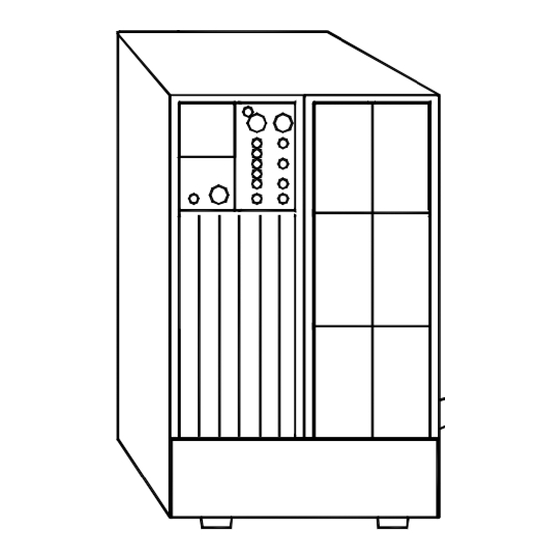
Page 11: External Dimensions And Part Names
Leave it set to “Inverter”. *2. Contact your supplier or a Sanyo Denki representative for more information about optional equipment. Refer to the Instruction Manual of the optional equipment for details about installation procedures and specifications. -
Page 12: Control Panel And Indicators
Part Names § § ⑭ ⑮ ⑩ ⑨ ⑯ ⑧ ⑦ ④ ⑥ ③ Indications of LED in this manual ⑫ The LEDs on the control panel are ⑬ described as “Green ON/OFF” or “Red ALARM”. ② The LEDs state are indicated as follows; ⑪... -
Page 13: External Interfaces
Part Names § § ② ① MAIN SW ④ ③ Name Function Connect the computer to this connector with the supplied Network cable. PC I/F ① The unit functions as follows, depending on the value of the Interface user setting. Set the Interface setting to select the functions that you want to use. -
Page 14: Part Names
⑥ ① 9 Bypass output 5 COM (common) Fixing screw inch For SANYO DENKI option cards only (cannot be used for other purposes) External transmission signals Signal name Description Active* when UPS is supplying battery power due to failure of AC input error utility power. - Page 15 Part Names Name Function REMOTE (2) These are connectors for remote ON/OFF signal input and for linked operation. ③ Connect an optional remote switch for remote control of UPS ON/OFF and computer Remote switch shutdown from a remote location, or connect an optional linked operation cable. connectors These connectors function as follows, depending on the setting of the Interface user setting.
- Page 16 Part Names Name Function AUX.OUTPUT These are terminals for connecting the optional outlet box and for use as EPO terminals ④ Connecting an outlet box to the UPS provides three output lines: OUTPUT0, 1, and 2. You can set External control ON/OFF delay times for OUTPUT1 and 2, allowing you to control system start and stop.
-
Page 17: Installation
Installation § § • When installing the UPS, carefully follow the instructions in this Instruction Manual. Improper installation can result in electric shock, bodily injury, and/or fire. • Install the UPS on a stable surface that can bear the weight (17 kg, 37.48 lbs). This surface should be flat, so the UPS cannot fall and cause bodily injury. -
Page 18: Installation
Installation § § • Do not sit, step or lean on the UPS, as bodily injury could result if the UPS was to fall. • The UPS weighs about (17 kg, 37.48 lbs). All work that involves lifting the UPS should !... -
Page 19: Wiring
Wiring § § § § • Wear insulated gloves and take other precautions when connecting the batteries. Otherwise electric shock can result. • There is a constant voltage (max. approx. 24V : approx. 12V × 2) at the battery ! terminals. -
Page 20: Connecting Optional Equipment
Software” and §18. “Using Optional Equipment” and the instruction manual supplied with the optional equipment. Contact your supplier or a SANYO DENKI representative for more information about optional equipment. MAIN SW Connecting a Network cable and using the power management software (on supplied CD-ROM)⇒... -
Page 21: Input Plug Connection
Wiring § § • Wiring should be performed only by technically qualified personnel. Incorrect wiring can result in electric shock and/or fire. • Check that the input power plugs are firmly seated. Failure to do so can result in ! electric shock, fire, or bodily injury. -
Page 22: Procedure Until Load Device Operation
Procedure Outline to Operation § § The procedure outline until turning on the load devices is as follows. Be sure to follow the procedure outline below to backup the load devices during power outage. Check the default value of the user setting ⇒... -
Page 23: Preparation Before Operation
Preparation Before Operation § § § § ① Check the user settings of the UPS. See §12.2 “Setup Menu List” to check the setting value. The factory default settings of the UPS are indicated by the “ * ” mark in the “Default Setting” column in the “Setup Menu List”. When the load specification, requirement or your When you use the UPS without changing environments do not configurate with the default... -
Page 24: Ups Charge
Preparation Before Operation § § Indications of Switch and LED in this manual. At initial startup or when the UPS is not operated The switches are indicated by a frame for long period, the UPS should be charged for at Example: MAIN SW least 12 hours before operation. -
Page 25: Outage Simulation Test
Preparation Before Operation § § Perform a power outage test to confirm whether the UPS is working properly. Be sure to perform this test prior to connecting the load devices. Step ① is not necessary if the procedure in §9.2 “UPS Charge” was performed beforehand. - Page 26 “Red ALARM” lights. Contact your supplier. Contact your supplier or SANYO DENKI when the “Red ALARM” lights or when the UPS does not operate properly even if you perform the countermeasure above. Check that the UPS operates properly, and then proceed to step ⑥.
-
Page 27: Load Devices Connection
Load devices connection § § Connect the load devices. ① Check that the input switch MAIN SW is set to “OFF”. ② Connect the input power plugs of the load devices to the output terminals. The total output from all output terminals must not exceed 1kVA (0.7kW). MAIN SW Switch is “OFF”. -
Page 28: Operating Procedures
Operating Procedures § § Operating procedures differ when you are using optional equipment. Refer to §18. “Using Optional Equipment” and to the Instruction Manual of the optional equipment. Indications of Switch and LED in this manual. § § The switches are indicated by a frame Example: MAIN SW The LEDs on the control panel are described as... - Page 29 Operating Procedures At this step, turn the load device power on. LEDs Green ON/OFF Green OUTPUT Green LOAD 25 -100% Green INVERTER Note for the load capacity “Green LOAD 25 - 100%” will light depending on the connected load capacities. If the “Red O.L”...
-
Page 30: Ups Shutdown (Daily)
Operating Procedures § § Perform the following operation to shut down the UPS daily. Be sure to shut down the load devices prior to shutting down the UPS. ① Press and hold for at least 1 second. Buzzer Musical trill LEDs All of the LEDs go off. -
Page 31: Ups Shutdown (If Not To Be Used For More Than A Week)
Operating Procedures § § Perform the following operation if the UPS is not to be used for at least a week. Be sure to shut down the load devices prior to shutting down the UPS. ① Press and hold for at least 1 second. Buzzer Musical trill LEDs... -
Page 32: User Settings
User Settings § § The UPS has a user settings menu, described in §12.2 “Setup Menu List”. You can set the various menu items to configure the UPS according to your environment, your applications, and the specifications of the User Settings Guide. connected load devices. -
Page 33: Setup Menu List
User Settings § § ●: indicates that LED is blinking. ○: indicates that LED is off. Setting Default Current User Settings Guide Menu Menu LED Setting Remarks Setting Setting Ref. page Item Do not use this setting. ●○○○ ○ Do not use this setting. ○●○○... - Page 34 User Settings Setting Default Current User Settings Guide Menu Menu LED Setting Remarks Setting Setting Ref. page Item Linked ON/OFF delay disabled No delay ● ○ ○ ○ ● Linked delay (operate with delay of 0 seconds) 3.16 operation ○ ○ ○ ○ Linked ON/OFF delay enabled Delay ○...
-
Page 35: Maintenance
Deal with a trouble or failure in the UPS. * What are service personnel? This term is used to indicate service technicians from SANYO DENKI or entrusted from SANYO DENKI with knowledge of this UPS. Maintenance work must not be performed by other than a qualified service technician. -
Page 36: Routine Checks
Maintenance § § • Be sure not to inspect the inside of the UPS. Doing so may result in an electric shock, burn, injury, smoke, or fire. • Do not touch the fan on the back panel of the UPS when cleaning the !... -
Page 37: Battery Test
Replacing the battery early is recommended. Result are OK. Contact SANYO DENKI. ② After the battery test has finished and the “Green BATT. TEST” indicator lights or blinking, press The “Green BATT. TEST” indicator goes off and returns to its normal indication. -
Page 38: Bypass Breaker Reset
Maintenance § § • Always power the UPS off before resetting the bypass breaker. Failure to do so ! can cause electric shock. Be careful to avoid injury or electric shock. CAUTION If the bypass breaker trips, the “Red ALARM” indicator lights and output from the output terminals stops. -
Page 39: Maintenance By Service Personnel
Maintenance § § The user must not perform the maintenance described in this section. ! Be sure to contact your supplier for maintenance. • Internal maintenance and inspection should be performed only by technically qualified personnel. Electric shock, injury, burning, fuming or fire could otherwise result. •... - Page 40 Maintenance ⑤ Pull the battery pack out. ⑥ Insert the new battery pack so that the connector faces forward. ⑥ Insert the new battery pack in the direction of the arrow. ⑦ Connect the battery connector. ⑧ Verify that Forced Bypass is set to “Inverter”. ⑨...
-
Page 41: Alarm Sounds
Alarm Sounds § § The buzzer sounds to indicate an UPS status error or change. Press to stop the buzzer. Check the sound pattern and refer to the following table for the steps to take. Sound Pattern LED Status UPS Status What to Do Red ALARM lit This is a mechanical failure. -
Page 42: Troubleshooting
Troubleshooting § § • Internal maintenance and inspection should be performed only by technically qualified personnel. Electric shock, injury, burning, fuming or fire could otherwise result. ! • Before beginning inspection, shut down the UPS completely, and remove the input power. - Page 43 Troubleshooting UPS Status LED Status Countermeasure • The alarm buzzer sound may be set to “OFF”. Alarm buzzer does not sound. Check the setting of “Buzzer Sound” in the user setting menu. User Settings Guide See §3.7 “Setting Buzzer Sound” in the •...
-
Page 44: How To Use Power Management Software
Power Management Software § § What is Power Management Software “SANUPS SOFTWARE STANDALONE” (supplied CD-ROM)? This software is used for power supply control or management from the computer by communicating the UPS to a computer (personal computer or workstation). Install power management software on your computer. For more information, refer to the Install Guide and User Guide in the CD-ROM of the power management software. - Page 45 When using the supplied “SANUPS SOFTWARE STANDALONE”, note the following instructions for the items on the main screen. See §6.1 “Main Screen” in the User Guide of SANUPS SOFTWARE STANDALONE for details. Main screen of SANUPS SOFTWARE STANDALONE UPS : A11H *** “Charge” of Battery Backup time “...
-
Page 46: Using Standard Os Ups Services
Using Standard OS UPS Services § § You can use the standard UPS service of your operating system to execute an automatic shutdown when power is lost. See §17.1 or §17.2, depending on your operating system. Use the supplied Network cable to connect the PC I/F connector on the UPS to the serial connector on the computer. -
Page 47: Windows 2000/Xp/Server 2003
Using Standard OS UPS Services § 2 Windows 2000/XP/Server 2003 § To make UPS settings, log in as a user with Administrator privileges. ① Select the “Power Option Properties” icon in the Control Panel, and then click the “Select...” button in the UPS tab. - Page 48 Using Standard OS UPS Services ④ Click the “Configure...” button. Click Configure... ⑤ Make the settings shown in the following figure, and then click the “OK” button. When you return to the screen in step ①, click “Apply”. Item Description A Enable all notifications Check this if you want to display all warning messages related to power failures.
-
Page 49: Using Optional Equipment
This section explains the procedures for connecting and operating optional equipment. For more information about optional equipment, contact your supplier or a SANYO DENKI representative. Refer to the relevant sections of this manual or to the documentation of the optional equipment for information about wiring, settings, and operating procedures. -
Page 50: Remote Switch
Optional Equipment § § This is a switch for turning the UPS ON and OFF from a remote location, and for executing one-touch shutdown* of connected computers. * What is one-touch shutdown? This is a function for sending a command requesting computer shutdown from the UPS to the power management software. -
Page 51: Linked Operation Cable
Optional Equipment § § What is linked operation? You can link up to 5 UPS units with cables and set their ON/OFF delay times, so that you can start and stop them in sequence. This is called linked operation. For linked operation, you will need linked operation cables and a remote switch. -
Page 52: Wiring And Settings For Linked Operation
Optional Equipment § § Before wiring, set MAIN SW on the back panel of each UPS to “OFF”, disconnect their input ! power plugs from the utility power outlets, and make sure that each UPS is completely stopped. CAUTION Failure to do so can result in electric shock. ①... -
Page 53: Linked Operation On Procedure
Optional Equipment § § Note about linked operation Linked operation starts or stops on an ON/OFF operation on the remote switch. It does not start or stop on an ON/OFF operation with the switch on the front panel. ① Check to be sure that all LEDs on all UPS units are off. -
Page 54: Linked Operation System Configuration
Optional Equipment § § The following figure shows linked operation for the case when ON delay and OFF delay times have been set for 3 UPS units. Remote switch ON/OFF operations control UPS output as shown below. Note that UPS operation in response to a remote switch OFF operation differs according to the Interface setting. -
Page 55: Outlet Box
Optional Equipment § § Use an outlet box if you want to control of the output from the UPS. What is output line control? Connecting an outlet box to the UPS provides three output lines: OUTPUT0, 1, and 2. You can set ON/OFF delay times for OUTPUT1 and 2, allowing you to control output start and stop. Operation that utilizes of this function is called “Output line control”. -
Page 56: Outlet Box Wiring And Settings
Optional Equipment § § Equipment you will need Outlet box Connection cable (supplied with outlet box) One outlet box is required for each UPS. Before wiring, set MAIN SW on the back panel of the UPS to “OFF”, disconnect the !... -
Page 57: Configuration Of An Output Line Control System
Optional Equipment § § When the ON/OFF delay settings of OUTPUT1 and OUTPUT2 are set as shown in the following table, and you turn the UPS ON and OFF, power is supplied as shown in the following figure. Example ON/OFF delay time settings for OUTPUT1 and OUTPUT2 Outlet ON delay time OFF delay time... -
Page 58: Combining A Remote Switch And Outlet Boxes
Optional Equipment § § You can connect a remote switch, linked operation cables, and outlet boxes to operate multiple UPS units with linked operation and output line control. The following figure shows an example of linked operation combined with output line control in a system with 2 UPS units. -
Page 59: Lan Interface Card
Optional Equipment § § Use the LAN interface card to perform UPS power management and computer shutdown. When you use the LAN interface card, the optional “SANUPS SOFTWARE” is required. This software provides network support, and is separate from the power management software supplied on the CD-ROM. For detailed information about connections and settings, refer to the Instruction Manual of the LAN interface card and the SANUPS SOFTWARE. -
Page 60: Contact Interface Card
Optional Equipment § § Connect the contact interface card when you want to use the external transmission signals (transistor output) of the UPS “CARD I/F” connector as no-voltage contact (relay contact) output. For detailed information about connections and so on, refer to the documentation of the contact interface card. -
Page 61: Connecting The Emergency Power Off (Epo) Terminals
Optional Equipment § § To enable emergency stop of UPS output, connect the contacts of a switch or other required device to EPO terminals 5 and 6 of the AUX.OUTPUT block. The switch to connect to the EPO terminals is not provided as a standard option for the UPS. Use a switch that complies with the following specifications, or connect to compliant contacts on your system. -
Page 62: Characteristic Of Ups
The “Red ALARM” indicator lights, and the alarm buzzer sounds. The power supply route is the same as for an overload. Output from the UPS will stop if a power outage occurs during bypass operation due to the UPS fault. Contact your supplier or SANYO DENKI as soon as possible. -
Page 63: Protective Function Table
Characteristics § § Indication of the marks in the table are as follows. Lit LED : Blinking LED : Buzzer Alarm : ① - ④ The following table shows functions and operations which activate to protect the UPS. Control panel (front panel) indicators Alarms Protective Item... -
Page 64: Specifications
Characteristics § § Item Standard or Performance Notes Output capacity 1kVA/0.7 kW Cooling system Forced air cooling Phases Single phase, 2-wire Voltage 55 to 150V Raged Voltage:120V (*6) Frequency 40 Hz to 120 Hz ±1, 3, 5%: Sync Range Power requirements 0.9 kVA Max. -
Page 65: Warranty
6. This warranty does not apply when the product is operated under extraordinary conditions, for example periodic complete discharge of the batteries. 7. This warranty is void in the event that the product supplied by Sanyo Denki is installed in an inappropriate location.
Need help?
Do you have a question about the SANUPS A11H and is the answer not in the manual?
Questions and answers