Table of Contents
Advertisement
Advertisement
Table of Contents

Subscribe to Our Youtube Channel
Related Manuals for Sanyo Denki SANUPS E11B


Summary of Contents for Sanyo Denki SANUPS E11B
- Page 1 M0012366 Uninterruptible Power Supply 1kVA 100V, 200V Instruction Manual...
-
Page 2: Table Of Contents
This term is used to indicate service technicians with technical expertise related to electrical equipment construction, or service technicians with knowledge of this UPS from SANYO DENKI or entrusted by SANYO DENKI. Construction and maintenance work must not be performed by any person other than a qualified service technician. - Page 3 5. USING THE UPS (APPLICATION) ....5.1 UPS Setting Menus ......................5.2 Starting the UPS in an Adverse Utility Power Environment ..........5.3 Using Power Management Software ................. 5.4 Using the LAN Interface Card ................... 5.5 Using the Contact Interface Card ..................5.6 Turning the UPS ON/OFF with the Remote Switch ............
-
Page 4: Introduction
INTRODUCTION_ Please read before product use. This chapter describes the procedures for using the UPS. Be sure to follow the procedures described in the instruction manual to ensure safe and proper UPS use. If you have purchased a model that supports long-term backup, see the instruction manual provided with the extension battery for extension battery related items. -
Page 5: Safety Precautions
Devices which serve applications related to the above. Contact your sales representative or SANYO DENKI if you need to use the UPS in an application like the above. Special equipment, such as redundant devices or an emergency generator, must be incorporated when operating, maintaining, and controlling systems in which a UPS is used with loads affecting life-support or public infrastructure-dependent applications. - Page 6 INTRODUCTION_ 2. Relocation, Transportation, and Moving Precautions CAUTION Be careful to avoid overturning or dropping the UPS during relocation, transportation, and moving. It may result in bodily injury. ! Be sure to work in at least pairs, and take care to prevent back strain. Do not tilt the UPS more than 10 degrees to either side when moving it vertically.
-
Page 7: Operating Precautions
INTRODUCTION_ 5. Operating Precautions PROHIBITED The UPS must be installed, operated, and maintained by technically qualified personnel in an industrial environment. This UPS should not be used in any other environment; for example, a general home environment where a technically qualified personnel is not present. - Page 8 Remarks HRL1234WF2FR (Hitachi Chemical Energy Technology), BPE11B102A00 SANYO DENKI 2 pcs Do not dispose of the used batteries yourself but rather contact your sales representative. The batteries in the UPS are lead type batteries. Lead type batteries are recyclable resources. Please recycle when replacing or disposing of used batteries.
-
Page 9: Ups Input Power Supply
INTRODUCTION_ The following table shows the rated AC input power of this UPS. Use the UPS with the output voltage set in accordance with the AC input power of the region of UPS use. Recommended breaker capacity Model name AC input voltage AC input frequency Input capacity of input distributor board... -
Page 10: Handling Precautions
INTRODUCTION_ (1) Never short-circuit the output circuits. Doing so will cause the protective functions of the UPS to activate or the breaker to trip, preventing output. (2) Unsuitable load equipment Never use the UPS in applications or with load equipment such as the below. Medical instruments used for life support. -
Page 11: Checking The Contents Of The Package
200 V Rack attachment plate screw SANUPS E11B Instruction Manual M4×6 SANUPS E11B Setting Menu Manual Warranty Card User Registration Outline The shape of the input cable differs according to the UPS model number. Check the cable provided with your UPS. -
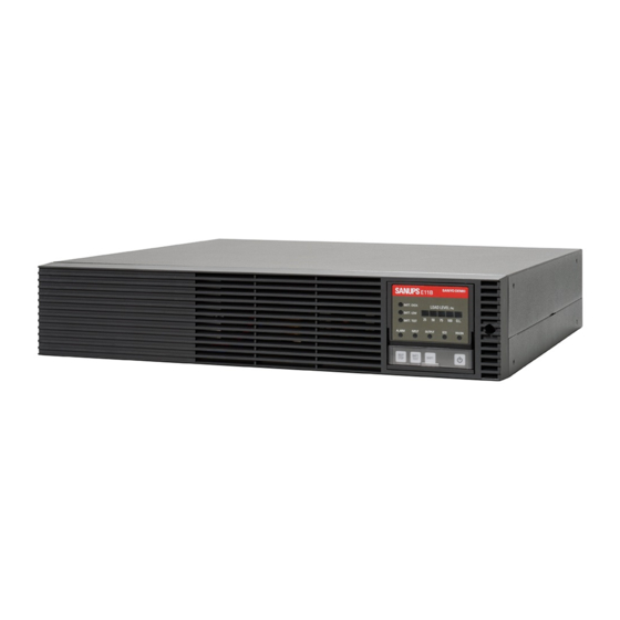
Page 12: Part Names
*1. The shape of the outlet and the shape of the input cable differ according to the UPS model number. Check the instruction manual provided with the UPS. In this instruction manual, a 100 V model UPS is described as an example. *2. For the various optional devices, contact your sales representative or SANYO DENKI. -
Page 13: Control Panel
_2. PART NAMES_ Name Description Indication Inverter ON/OFF button Starts and stops inverter operation • Stops the buzzer when the buzzer is sounding. In Normal mode • Clears the battery test result. • Switches to Setting mode when held down for 3 seconds. Buzzer stop button •... -
Page 14: Ups Installation
_3. UPS INSTALLATION_ Installation of the UPS must be carried out following the instructions in this instruction manual. Improper installation may result in an electric shock, bodily injury, and/or a fire. In accordance with the instruction manual, install the UPS on a surface that can bear the UPS weight (15 !... -
Page 15: Mounting The Ups On A Rack
_3. UPS INSTALLATION_ Securely mount the UPS on a rack. Vibration and shock such as an earthquake may cause the UPS to move or fall, possibly resulting in bodily injury. The weight of the UPS is 15 kg. Wear safety shoes during the installation. All work that involves lifting the UPS should !... -
Page 16: Installing The Ups Horizontally
_3. UPS INSTALLATION_ Do not sit, step, or lean on the UPS or carry out any other such conduct. It may result in bodily injury. The weight of the UPS is 15 kg. Wear safety shoes during the installation. All work that involves lifting the UPS should be !... -
Page 17: Applying The Installation Date Label
_3. UPS INSTALLATION_ Enter the UPS installation date on the supplied installation date label for reference for the next battery replacement, and apply the label in a location that can be checked easily. (1) Prepare the following items supplied with the product. 年... -
Page 18: R E A D T H I S T O S T A R T U S I N G Y O U R Uupsing P Ups
_4. USING THE UPS (BASICS)_ ! Use the UPS following the instructions in this instruction manual. Improper use may result in an electric shock, bodily injury, and/or a fire. CAUTION The following describes the basic steps for the basic operation of providing power supply backup to load equipment such as a PC. For details on UPS functions and settings, such as control panel setting menu items, how to use optional devices, and external transmission signals, see “5. - Page 19 _4. USING THE UPS (BASICS)_ Step Operation Remarks Insert the UPS input plug into the utility power supply (wall outlet, etc.). Connect the UPS input cable as follows according to the local power supply environment Fully insert the plug so that the plug is not loose. in which the UPS will be used.
- Page 20 _4. USING THE UPS (BASICS)_ Step Operation Remarks Conduct the power outage simulation test following the steps below. Unplug the input plug to simulate a power outage, and check operation during the power 9-1 Unplug the UPS input plug from the utility supply outlet. outage.
- Page 21 _4. USING THE UPS (BASICS)_ Step Operation Remarks Connect the load equipment to the output outlets on the back of the UPS. Connect the load equipment as follows according to the local power supply Fully insert the plugs of the load equipment so that plugs are not loose. environment in which the UPS will be used.
-
Page 22: Operation Procedures
_4. USING THE UPS (BASICS)_ Follow the procedure below to start the UPS. In this section, the 100 V model UPS is described as an example. Perform the same operation with the 200 V model UPS as well. Step Operation Remarks Check that the input cable is connected. - Page 23 _4. USING THE UPS (BASICS)_ Step Operation Remarks Turn on the power of the load equipment. If the UPS state is as described below when the power of the load equipment is turned on, the load equipment connected to the UPS exceeds the rated [LOAD LEVEL(%)] is lit in capacity of the UPS.
-
Page 24: Shutting Down The Ups
_4. USING THE UPS (BASICS)_ Follow the procedure below to shut down the UPS. In this section, the 100 V system UPS is described as an example. Perform the same operation with the 200 V system UPS as well. Step Operation Remarks Be sure to shut down the load equipment before... - Page 25 _4. USING THE UPS (BASICS)_ Blank page...
-
Page 26: Using The Ups (Application)
You can run the UPS in accordance with your system by configuring the various UPS functions and connecting optional devices. For various optional device details, contact your sales representative or SANYO DENKI. The UPS is provided with the setting menus described in the table below. Set the menus according to your environment, system, and operation method. -
Page 27: Starting The Ups In An Adverse Utility Power Environment
_5. USING THE UPS (APPLICATION)_ When the input power supply is in an abnormal state (power outage or low voltage), start the UPS following the procedure below. When the UPS is started using this procedure, power is supplied to the load devices from the installed batteries. Be sure to use the load devices within the period that backup from the UPS is possible. -
Page 28: Using Power Management Software
The power supply management software download the software from the “SANUPS SOFTWARE” is an optional product home page of SANYO DENKI. (charge applied). For option details, contact your sales representative or SANYO DENKI. Specify the following settings in the setting menu. - Page 29 The following describes the procedure for downloading the power management software “SANUPS SOFTWARE STANDALONE” (free version). For downloading the power management software “SANUPS SOFTWARE” (charge applied), contact SANYO DENKI or your supplier. Step Description Access the URL below, and open the page.
-
Page 30: Using The Lan Interface Card
_5. USING THE UPS (APPLICATION)_ The LAN interface card (option) is used when managing the UPS power supply or shutting down the computer via LAN. For details on the connection and setup method, see the instruction manual and user guide of the LAN interface card. UPS ... -
Page 31: Using The Contact Interface Card
The contact interface card is an option. For option details, contact your sales representative Contact interface card Contact interface card or SANYO DENKI. Communication cable (Supplied with contact interface card.) If the UPS is running, stop the UPS by performing the procedure in “4.2.2 Unplug the UPS input plug from the outlet or turn the outlet breaker OFF, and shut down the UPS. -
Page 32: Turning The Ups On/Off With The Remote Switch
_5. USING THE UPS (APPLICATION)_ This UPS allows you to connect a switch, such as a pushbutton switch, to the “REMOTE” terminal on the back of the UPS, and start and shut down the UPS from a remote location. REMOTE terminal The signals of the “REMOTE”... - Page 33 Remarks The remote switch is provided as an option as well. Prepare the switch in accordance with the system. For option details, contact your sales representative or SANYO DENKI. REMOTE ON OFF Remote switch Unplug the UPS input plug from the outlet or turn the If the UPS is running, stop the UPS by performing the procedure in “4.2.2...
-
Page 34: Connecting The Ups Emergency Stop Switch
_5. USING THE UPS (APPLICATION)_ Connect the UPS emergency stop switch to the EPO terminal*. When the switch is pressed when there is an emergency, UPS output will stop. *. EPO stands for “Emergency Power Off”. EPO terminal EPO Terminal Specifications When using a transistor or other semiconductor switch, •... - Page 35 _5. USING THE UPS (APPLICATION)_ Step Description Remarks Check the operation of the connected EPO switch with the UPS normally When you check operation with load equipment connected to the UPS, be sure to first shut down the running. load equipment. 4-1 Check that [OUTPUT (green)] is lit while the UPS is running.
-
Page 36: Using Ups External Transmission Signals
_5. USING THE UPS (APPLICATION)_ The external transmission signals in the table below are output from the “CARD I/F” connector of the UPS. Connect devices in accordance with your system and specifications. If dry contact output is required, see “5.5 Using the Contact Interface Card”. External transmission signals of CARD I/F connector The external transmission signals in the table below are output from the “CARD I/F”... - Page 37 _5. USING THE UPS (APPLICATION)_ Blank page...
-
Page 38: Inspection And Maintenance
This term is used to indicate service technicians with technical expertise related to electrical equipment construction, or service technicians with knowledge of this UPS from SANYO DENKI or entrusted by SANYO DENKI. Construction and maintenance work must not be performed by any person other than a qualified service technician. - Page 39 If there is any damage such as a dent or deformation that may affect the Is the exterior in any way damaged or deformed? UPS interior, contact your sales representative or SANYO DENKI. Do not use the UPS as is. Doing so is dangerous.
-
Page 40: Checking The Battery Replacement Time
Check the time for battery replacement using the following methods A, B, and C, and if the result of one method indicates it is time to replace the batteries, replace them. For battery replacement, contact your sales representative or SANYO DENKI. - Page 41 The battery service life has ended. as soon as possible. Replace the batteries Replace the batteries Contact your sales representative or SANYO DENKI. Contact your sales representative or SANYO DENKI. Press to stop the buzzer. The lit or blinking state of the LED will continue until the battery information is reset after battery replacement.
-
Page 42: Running A Battery Test
Contact your [BATT.TEST (green)]: Lit Continues (7 times) Buzzer sound: None sales representative or SANYO DENKI. Replacing the batteries now is The battery is normal. recommended. Contact your sales representative or SANYO DENKI. - Page 43 The interval by which you want to run the battery test automatically can be changed. See “2.21 Setting the Battery Test Schedule” in the Setting Menu Manual. The battery test result serves as a general guide only. Even if the result is normal, contact your supplier or SANYO DENKI as soon as possible if the possibility exists that the batteries have deteriorated.
-
Page 44: Resetting The Bypass Breaker
_6. INSPECTION AND MAINTENANCE_ When the bypass breaker “BYPASS OC” on the back of the UPS trips, the control panel changes to the state below and power supply from the output outlet stops. Follow the procedure below to reset the breaker. Step Operation Remarks... - Page 45 _6. INSPECTION AND MAINTENANCE_ Blank page...
-
Page 46: Switching The Operation Between Bypass And Inverter
During UPS synchronous operation, the UPS switches to bypass operation without interruption. During asynchronous operation, the UPS switches with interruption. When the UPS malfunctioned and the output power supply stopped, you cannot switch to bypass operation by the procedure below. Contact your sales representative or SANYO DENKI. Step Operation Remarks Check that the control panel is as follows. -
Page 47: Switching From Bypass To Inverter Operation
_6. INSPECTION AND MAINTENANCE_ Note on switching to inverter power supply Performing the procedure wrong results in the risk of UPS failure or suspension of output. Be sure to perform the switching operation as described in the procedure. Step Operation Remarks Check that the control panel is as follows. -
Page 48: When A Buzzer Sounds
The UPS ambient When the ambient temperature exceeds 40 C (104 F), the battery ALARM (red) Blinking temperature is high. charging stops. Note If any other trouble occurs or you think there is a malfunction, contact your sales representative or SANYO DENKI. -
Page 49: Troubleshooting
Blinking When the UPS input plug was inserted into a utility power outlet, the buzzer The batteries need to be replaced. Contact your sales representative or SANYO DENKI. BATT.EXCH. sounded. When this display continues even after the batteries have been replaced, the battery (orange) information has not been reset. - Page 50 If you want to stop output during bypass operation, unplug the input plug. Bypass power supply will continue during bypass operation caused by a UPS malfunction. Contact your sales representative or SANYO DENKI. ALARM (red) Lit If you want to stop output during bypass operation, unplug the input plug.
- Page 51 Has the bypass breaker “BYPASS OC” tripped? See “6.3 Resetting the Bypass Breaker”. ALARM (red) Lit The UPS has malfunctioned. Contact your sales representative or SANYO DENKI. For some reason or other, the battery test did not end normally. BATT.TEST (green) The UPS may be in a state in which the battery test is not possible or the battery The battery test did not end normally.
- Page 52 Setting Menu Manual, and check the setting value. Note If the UPS does not operate normally even if you perform the countermeasures above, or if any other trouble occurs or you think there is a malfunction, contact your sales representative or SANYO DENKI.
-
Page 53: Ups Characteristics
[ALARM (red)] lights, and the buzzer sounds. The power supply path is the same as that when overload occurs. When a power outage occurs during bypass power supply due to a UPS malfunction, output stops. Contact your sales representative or SANYO DENKI. -
Page 54: Protective Function Table
_9. UPS CHARACTERISTICS_ Indication of the marks in the table as follows. LED Lit: LED Blinking: Alarm buzzer: (1) ~ (5) The following table shows the functions and operations for protecting the UPS. Control Panel (Front Panel) Display Alarm Protection BATT. -
Page 55: Specifications
_9. UPS CHARACTERISTICS_ Item Standard or Characteristics Notes Model E11B102A001 E11B102A002 Output capacity 1 kVA / 0.8 kW Cooling system Forced air cooling Input plug NEMA 5-15P IEC60320-C14 Inlet IEC60320-C14 Number of phases Single-phase 2-wire 55 to 150 V 110 to 300 V When in Double Conversion mode Note 2 Voltage...
Need help?
Do you have a question about the SANUPS E11B and is the answer not in the manual?
Questions and answers