Table of Contents
Advertisement
Quick Links
Advertisement
Table of Contents

Related Manuals for Advantech APAX-5000 Series


Summary of Contents for Advantech APAX-5000 Series
- Page 1 User Manual APAX-5000 Series I/O Modules...
- Page 2 No part of this manual may be reproduced, copied, translated or transmitted in any form or by any means without the prior written permission of Advantech Co., Ltd. Information provided in this manual is intended to be accurate and reliable. How- ever, Advantech Co., Ltd.
- Page 3 This product has passed the CE test for environmental specifications when shielded cables are used for external wiring. We recommend the use of shielded cables. This kind of cable is available from Advantech. Please contact your local supplier for ordering information.
- Page 4 The sound pressure level at the operator's position according to IEC 704-1:1982 is no more than 70 dB (A). DISCLAIMER: This set of instructions is given according to IEC 704-1. Advantech disclaims all responsibility for the accuracy of any statements contained herein.
-
Page 5: Table Of Contents
Contents Chapter Overview..........1 Introduction ....................2 Table 1.1: Supported I/O Module List.......... 2 I/O Wiring ....................4 Removing the I/O Terminal ............... 5 Labeling the Terminal................6 Jumper Settings ..................7 ID Switch Setting..................8 Mechanical Assembly and Power Connection ........10 1.7.1 Wiring Power Input to the Backplane.......... - Page 6 3.1.4 APAX-5040PE 24-ch Digital Input Module for P&E Applications 49 Figure 3.7 APAX-5040PE Module Front View......49 Figure 3.8 Wiring for APAX-5040PE ......... 50 3.1.5 APAX-5046SO 20-ch Digital Output Module ......51 Figure 3.9 APAX-5046SO Module Front View ......51 Figure 3.10Wiring for APAX-5046SO .........
- Page 7 Enable, Rising Edge, Not Retriggerable....91 Figure 3.48Pulse/DIR , With Reload , Count Once, DI Gate Enable, Rising Edge, Retriggerable........92 Figure 3.49Pulse/DIR , With Reload , Count Repetitively, DI Gate Enable, Rising Edge, Retriggerable ......93 Figure 3.50Pulse/DIR, With Reload, Count Once, DI Gate Enable, Falling Edge, Not Retriggerable .......
- Page 8 APAX-5000 I/O Series User Manual viii...
-
Page 9: Chapter 1 Overview
Chapter Overview... -
Page 10: Introduction
Introduction This manual will discuss the specifications, functions and application wiring of the APAX-5000 series of I/O modules. Advantech provides different APAX-5000 I/O mod- ules for various applications. The following table outlines Advantech's supported I/O modules. Table 1.1: Supported I/O Module List... - Page 11 APAX-5000 I/O Series User Manual...
-
Page 12: I/O Wiring
I/O Wiring APAX-5000 I/O modules leverage detachable clamp type terminal blocks. Comparing with traditional screw type terminal blocks, clamp type terminal blocks can save up to 75% wiring time and provide better reliability for shock and vibration. Follow the pro- cedures below for wiring your APAX-5000 I/O module. -
Page 13: Removing The I/O Terminal
Removing the I/O Terminal APAX-5000 I/O modules provide detachable terminal blocks that are convenient when wiring needs to be changed, because the terminal block can removed and the module doesn't need to be. Refer to the figures below to remove the terminal block. Warning! APAX-5000 I/O modules can be categorized into four categories: AI, AO, DI and DO. -
Page 14: Labeling The Terminal
Labeling the Terminal Advantech provides write-on labels for each APAX-5000 I/O module. This write-on label has two sides, one with the model name, specifications and a wiring diagram, while the other side allows users to write information in by themselves. Refer to the figures below for the write-on label details. -
Page 15: Jumper Settings
Jumper Settings Some I/O modules need to be configured manually through the onboard jumpers. This section will show you how to adjust the jumper settings. Pull out the write-on label and you can see the location of the jumper. You can use the screw driver to adjust the jumper setting. Once the jumper setting is done, slide the write-on label back to its position. -
Page 16: Id Switch Setting
ID Switch Setting The controller identifies each APAX-5000 I/O module through the ID number. There- fore, you need to set ID number for each I/O module by the rotary ID switch on the front side. Rotate that ID switch and point the hole on the central axis to correspond- ing ID number ("0"... - Page 17 You can distinguish if the ID number is doubled by the front LED. When the LED color is green, only 0 ~ 15 ID number is used (0 ~ 15 according to the rotary ID switch). Once the LED color is orange, the ID number is doubled (16~31 according to the rotary ID switch).
-
Page 18: Mechanical Assembly And Power Connection
Mechanical Assembly and Power Connection 1.7.1 Wiring Power Input to the Backplane There are two ways that APAX-5000 I/O mdoules can be powered. One is to connect the DC power supply wire directly to the power connector on the backplane. Another way is using APAX-5343E power supply module. - Page 19 Lock that APAX-5000 I/O module to the APAX-5002 backplane by pulling down the module locks. Insert another APAX-5000 I/O module on the same APAX-5002 backplane. Use tongue-and-groove slots to move the module. Lock that APAX-5000 I/O module to the APAX-5002 backplane by pulling down the module locks.
- Page 20 If you need more than one APAX-5000 I/O module, stack another APAX-5002 backplane to the original APAX-5002 backplane. Warning! When you assembly different backplanes together, remember to turn off the power connected to the backplane. If not, the backplanes may be damaged.
- Page 21 Insert another APAX-5000 I/O module on the second APAX-5002 backplane. Lock that APAX-5000 I/O module to the second APAX-5002 backplane by pull down the module locks, similar as step 5. If needed, repeat step 8 ~ 9 to have another APAX-5000 I/O module on the same APAX-5002 backplane.
-
Page 22: Using The Apax-5343E Power Supply Module
1.7.2 Using the APAX-5343E Power Supply Module APAX-5000 I/O modules can also be powered by the APAX-5343E power supply module, connected to the left side of the whole system. The power can be transferred to APAX-5000 I/O modules though the backplanes. Note! Refer to Chapter 5 for APAX-5343E specifications. - Page 23 APAX-5000 I/O Series User Manual...
- Page 24 Stack the backplane of APAX-5343E to the left side of the first APAX-5002 back- plane in the system. Lock the stacked APAX-5343E backplane with the APAX-5002 backplane by the backplane locks on the APAX-5002 backplane. Insert the upper case of APAX-5343E back to its backplane. Use tongue-and- groove slots to move the upper case.
-
Page 25: Decommission And Disposal
Lock the upper case of APAX-5343E to its backplane by pulling down the mod- ule locks on the upper case. Connect AC power code to the power connectors on the upper case of APAX-5343E. Then the whole system is powered-on. Decommission and Disposal APAX-5000 I/O modules support hot-swap functionality. -
Page 26: Mounting
Detach APAX-5000 I/O module from the backplane. Repeat Step 1 ~ Step 2 for all the APAX-5000 I/O modules you want to remove. It is the similar when you insert APAX-5000 I/O modules back to the backplane. First, insert APAX-5000 I/O module to backplane. Then, pull down the two module locks to lock on the backplane, and APAX-5000 I/O module will be power-on and can be used. - Page 27 Attach the APAX-5002 backplane on the DIN rail. Repeat Step 1 ~ Step 2 until necessary APAX-5002 backplanes are all attached on the DIN rail. Note! When the total number of APAX-5520 and APAX-5000 I/O modules is odd, you can use APAX-5001 (1-slot backplane) as the last backplane in the system.
-
Page 28: Wall (Panel) Mounting
1.9.2 Wall (Panel) Mounting Mount the APAX-5000 I/O module to a wall (panel) through backplane using two screws per module. Use M4 or #8 panhead screws. Refer to figure below for the dimensional template: Below are the procedures for the wall (panel) mounting: Pull down the DIN-rail lock at the back of the first APAX-5002 backplane. - Page 29 Hang the APAX-5002 backplane onto the screw on the wall (panel). The screw for APAX-5002 to hang should be special-designed. We have provided it in accessory. (Diameter: 9 mm, length: 16 mm, height of head: 2.7 mm) Mount the first APAX-5002 backplane to the wall (panel) using two standard M4 or #8 panhead screws.
- Page 30 Stack Another APAX-5002 backplane to original backplane. Lock the two back- planes together. Mount the second APAX-5002 backplane to the wall (panel) using two standard M4 or #8 panhead screws. APAX-5000 I/O Series User Manual...
- Page 31 Repeat Step 4 ~ Step 5 until all necessary APAX-5002 backplane are screwed on the wall (panel). Note! When the total number of APAX-5000 I/O modules is odd, you can use APAX-5001 (1-slot backplane) as the last backplane in the system. The procedure to attach APAX-5001 on the wall is similar as APAX-5002.
- Page 32 We suggest remaining enough clearance space from enclosure walls and adjacent equipments. Allow 50 mm (2 in.) of space on all sides, as shown below. This provide ventilation and makes assembly more easily. APAX-5000 I/O Series User Manual...
-
Page 33: Chapter 2 Analog Input/Output Modules
Chapter Analog Input/Output Modules... -
Page 34: Analog Input Modules
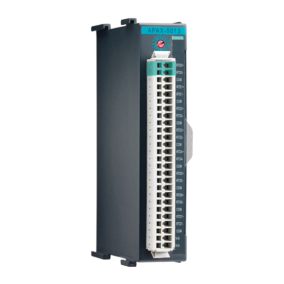
Analog Input Modules Analog input modules use an A/D converter to convert sensor voltage, current, ther- mocouple or RTD signals into digital data. The analog input modules protect your equipment from ground loops and power surges by providing opto-isolation of the A/ D input and transformer based isolation up to 2,500 VDC. - Page 35 Application Wiring Figure 2.2 Wiring for APAX-5013 APAX-5013 Technical Specifications Channels: 8 Input Impedance: >10 M Input Type: Pt-100, Pt-200, Pt-500, Pt-1000, Balco, Ni 518 RTD (2-wire and 3-wire) Temperature Range: Pt-100,Pt-200,Pt-500,Pt-1000: -120~130C, -200~850C Supports IEC 60751 ITS90 (0.03851// C) and JIS C 1604 (0.03916 // C) –...
-
Page 36: Apax-5017 12-Ch Analog Input Module
2.1.2 APAX-5017 12-ch Analog Input Module The APAX-5017 is a 16-bit, 12-channel analog differential input module that provides programmable input ranges on all channels, and different channels can be configured using different ranges. It accepts voltage and current inputs. Adjust the switch (refer to Section 1.5) to define each channel as voltage or current input. - Page 37 Note! To keep measurement accuracy please short the channels that are not in use. Note! You can use the jumpers to configure each analog input channel type (voltage or current). Refer to Section 1.5 for the location of the jumpers. There are a total of 12 jumpers and each is specific for one channel.
-
Page 38: Apax-5017H 12-Ch High Speed Analog Input Module
Protection Isolation: 2,500 VDC (Between channels and backplane bus) Over Voltage Protection: ±35 VDC Environment Operating Temperature: -10 ~ 60 C (when mounted vertically) Storage Temperature: -40 ~ 70 C Relative Humidity: 5 ~ 95% (non-condensing) General ... - Page 39 Application Wiring Figure 2.6 Wiring for APAX-5017H Note! You can use the jumpers to configure each analog input channel type (voltage or current). Refer to Section 1.5 for the location of the jumpers. There are a total of 12 jumpers and each is specific for one channel. APAX-5017H Specifications ...
-
Page 40: Apax-5018 12-Ch Thermocouple Input Module
General Dimensions (W x H x D): 30 x 139 x 100 mm Weight: 175 g Power Consumption: 3.5 W @ 24 VDC (typical) Warning! There is no built-in filter on APAX-5017H module, so it is not very suit- able to use it in a very noisy environment. - Page 41 Application Wiring Figure 2.8 Wiring for APAX-5018 Note! You can use the jumpers to configure each analog input channel type (voltage/thermocouple or current). Refer to Section 1.5 for the location of the jumpers. There are a total of 12 jumpers and each is specific for one channel.
- Page 42 Note! This accuracy information only relates to the operating error, not includ- ing cold connection CJC error. The CJC error can be eliminated by per- forming CJC compensation. Configure Different Range for Each Channel: Yes Resolution: Voltage Range Resolution ±50 mV 16 bit...
- Page 43 Environment Operating Temperature: -10 ~ 60 C (when mounted vertically) Storage Temperature: -40 ~ 70 C Relative Humidity: 5 ~ 95% (non-condensing) General Dimensions (W x H x D): 30 x 139 x 100 mm Weight: 170 g ...
-
Page 44: Apax-5017Pe 12-Ch Analog Input Module For P&E Applications
2.1.5 APAX-5017PE 12-ch Analog Input Module for P&E Applications The APAX-5017PE is a 16-bit, 12-channel analog differential input module that provides programmable input ranges on all channels, and different channels can be configured using different ranges. It accepts voltage and current inputs. You can use software (APAX utility) to configure range type for each channel. - Page 45 Note! To keep measurement accuracy please short the channels that are not in use. Technical Specifications of APAX-5017PE Channels: 12 (Differential) Input Impedance: >10 M (Voltage) Input Type: V, mV, mA (for current mode, 120 resistors is required to be connected in parallel) ...
- Page 46 Environment Operating Temperature: -20 ~ 70C (when mounted vertically) Storage Temperature: -40 ~ 85C Relative Humidity: 5 ~ 95% (non-condensing) General Dimensions (W x H x D): 30 x 139 x 100 mm Weight: 170 g ...
-
Page 47: Analog Output Modules
Analog Output Modules 2.2.1 APAX-5028 8-ch Analog Output Module The APAX-5028 is a 8-channel analog output module. It uses the D/A converter con- trolled by the system module to convert the digital data into output signals. You can specify slew rates and start up currents through the configuration software. For each channel, voltage and current can be used by connecting to different terminal. -
Page 48: Apax-5028 Specifications
Application Wiring Figure 2.12 Wiring for APAX-5028 Note! The common terminals are physically connected together and to the backplane power supply ground. 2.2.2 APAX-5028 Specifications Channels: 8 Output Type: V, mA Output Range: ±2.5 V, ±5 V, ±10 V, 0~2.5 V, 0~5 V, 0~10 V, 0~20 mA, 4~20 mA ... -
Page 49: Chapter 3 Digital Input/Output Modules
Chapter Digital Input/Output Modules... -
Page 50: Digital Input/Output Modules
Digital Input/Output Modules 3.1.1 APAX-5040 24-ch Digital Input Module The APAX-5040 features 24 digital input (sink/source) channels. The APAX-5040 module's digital input channels can accept a 2-wiring input from a DC voltage source, to determine the state of limits, standard switches or proximity switches. The digital input channels offer LED to indicate digital status. - Page 51 APAX-5040 Specifications Digital Input Channels: 24 Points per Common: 12 Type: Sink/Source (Wet Contact) Input Voltage Rated Value: 24 VDC – For "0" signal: -5 ~ 5 VDC – For "1" signal: 15 ~ 30 VDC and -15 ~ -30 VDC ...
-
Page 52: Apax-5045 24-Ch Digital Input/Output Module
3.1.2 APAX-5045 24-ch Digital Input/Output Module The APAX-5045 features 12 digital input (sink/source) and 12 digital output (sink) channels. The APAX-5045 module's digital input channels can accept a 2-wiring input from a DC voltage source, to determine the state of limits, standard switches or proximity switches. - Page 53 Application Wiring Figure 3.4 Wiring for APAX-5045 Warning! When you connect DO channel with inductive load, we suggest adding one diode in the circuit to protect the APAX-5045 module. (Refer to fig- ure below) APAX-5045 Specifications Digital Input Channels: 12 ...
- Page 54 Digital Output Channels: 12 Type: Sink Voltage Range: 8 ~ 35 VDC Rated Output Current at signal "1": 0.5 A (per channel) Permitted Output Current (at signal "1"): max. 0.75 A Output Current at signal "0" (leakage current): 0.1 mA ...
-
Page 55: Apax-5046 24-Ch Digital Output Module
3.1.3 APAX-5046 24-ch Digital Output Module The APAX-5046 features 24 digital output (sink) channels. The digital output chan- nels offer short-circuit protection and LED to indicate digital status. The module pro- vides 2500 VDC optical isolation between channels and backplane bus. If any high voltage or current damage the channels, the whole system (backplanes, other mod- ules, and control unit) won't be affected because it is already isolated. - Page 56 APAX-5046 Specifications Digital Output Channels: 24 Type: Sink Voltage Range: 8 ~ 35 VDC Rated Output Current at signal "1": 0.5 A (per channel) Permitted Output Current (at signal "1"): max. 0.75 A Output Current at signal "0" (leakage current): 0.1 mA ...
- Page 57 3.1.4 APAX-5040PE 24-ch Digital Input Module for P&E Applications The APAX-5040PE features 24 digital input (sink/source) channels. The APAX- 5040PE module's digital input channels can accept a 2-wiring input from a DC volt- age source, to determine the state of limits, standard switches or proximity switches. The digital input channels offer LED to indicate digital status.
- Page 58 Application Wiring Figure 3.8 Wiring for APAX-5040PE APAX-5040 Specifications Digital Input Channels: 24 Points per Common: 12 Type: Sink/Source (Wet Contact) Input Voltage Rated Value: 24 VDC – For "0" signal: -5 ~ 5 VDC – For "1"...
- Page 59 3.1.5 APAX-5046SO 20-ch Digital Output Module The APAX-5046SO features 20 digital output (source) channels. The digital output channels offer short-circuit protection and LED to indicate digital status. The module provides 2500 VDC optical isolation between channels and backplane bus. If any high voltage or current damage the channels, the whole system (backplanes, other modules, and control unit) won't be affected because it is already isolated.
- Page 60 APAX-5046SO Specifications Digital Output Channels: 20 Type: Source Voltage Range: 10 ~ 35 V Rated Output Current at signal “1”: 1A (per channel) Permitted Output Current (at signal “1”): max. 1.2A Output Current at signal “0” (leakage current): 0.1 mA ...
- Page 61 Relay Output Modules 3.2.1 APAX-5060 12-ch Relay Output Module The APAX-5060 relay output module provides 12 relay channels of Form A. Switches can be used to control the relays. The digital output channels offer short-circuit protec- tion and LED to indicate digital status. The module provides 2500 VDC optical isolation between channels and backplane bus.
- Page 62 Application Wiring Figure 3.12 Wiring for APAX-5060 Warning! When you connect DO channel with inductive load, we suggest adding one diode in the circuit to protect the APAX-5060 module. (Refer to fig- ure below) APAX-5000 I/O Series User Manual...
- Page 63 APAX-5060 Specifications Relay Output Channels: 12 Relay Type: Form A (SPST) Switching Capacity and Lifetime of the Contact (For Resistive Load) – VDE: 30,000 operations (5 A @ 250 VAC, 10 operations/minute at 8 C) 70,000 operations (5 A @ 30 VDC, 10 operations/ minute at 85 C) –...
- Page 64 3.2.2 APAX-5060PE 12-ch Relay Output Module for P&E Applications The APAX-5060PE relay output module provides 12 relay channels of Form A. Switches can be used to control the relays. The digital output channels offer short-circuit protec- tion and LED to indicate digital status.This module is an IEC-61850-3 compliant I/O modules, and suitable for power and energy related application.
- Page 65 Warning! When you connect DO channel with inductive load, we suggest adding one diode in the circuit to protect the APAX-5060PE module. (Refer to figure below) APAX-5060PE Specifications Relay Output Channels: 12 Relay Type: Form A (SPST) Switching Capacity and Lifetime of the Contact (For Resistive Load) –...
- Page 66 Dimensions (W x H x D): 30 x 139 x 100 mm Weight: 195 g Power Consumption: 2 W @ 24 VDC (typical) Status Display: LED per channel – On: Logic level “1” – Off: Logic level “0” APAX-5000 I/O Series User Manual...
- Page 67 Counter Modules 3.3.1 APAX-5080 Counter/Frequency and DIO Module The APAX-5080 features counter/frequency and DIO functions. For the digital input function, the APAX-5080 supports 4 isolated digital input and Gate function. For digi- tal output function, the APAX-5080 supports 4 general isolated digital output and spe- cific alarm function with counter.
- Page 68 Application Wiring Figure 3.16 Wiring for APAX-5080 Warning! Please use different power supply modules for digital channels and sys- tem to ensure isolation effect. APAX-5000 I/O Series User Manual...
- Page 69 APAX-5080 Function Block APAX-5000 I/O Series User Manual...
- Page 70 APAX-5080 Specifications Digital Input Channels: 4 Input Voltage – For “0” Signal: 0 ~ 3 VDC – For “1” Signal: 10 ~ 30 VDC Input Current: 5~15 mA (For Signal “1”, typical) Minimum Pulse Width: 500 ns (Max. Input Frequency) Digital Output ...
- Page 71 General Dimensions (W x H x D): 30 x 139 x 100 mm Weight: 165 g Power Consumption: 2.5 W @ 24 VDC (typical) Status Display: LED per channel – On: Logic level “1” – Off: Logic level “0” APAX-5080 Counter Mode No Gate No Alarm There are so many counter modes in APAX-5080 and below will use counter0 as an example to explain every counter mode operation principle.
- Page 72 Ch0_A Ch0_B Down Counter0 Enable Counter0 0x33 0x32 0x31 0x32 0x33 0x34 0xF..F 0x00 ……… Value Counter 0 Overflow Figure 3.17 Pulse/DIR, No Reload, Count Once Pulse/DIR, With Reload, Count Once Figure 3.4 shows pulse/direction mode, Ch0_A provides the counting function, one pulse, one count.
- Page 73 Pulse/DIR, With Reload, Count Repetitively Figure 3.5 shows pulse/direction mode, Ch0_A provides the counting function, one pulse, one count. Ch0_B provides the clockwise and counter clockwise function. When the counter0 is enabled, the couner0 starts to count. If the counter value is overflow or underflow, it will reset to the defined value (e.g.
- Page 74 Up/Down, No Reload, Count Once Figure 3.6 shows up/down mode, Ch0_A provides the counting up function, one pulse, one up count. Ch0_B provides the counting down function, one pulse, one down count. When the counter0 is enabled, the couner0 starts to count. If the counter value is overflow or underflow, it will show the minimum (0x00) or maximum (0xFFFFFFFF) value and not count continuously.
- Page 75 Up/Down, With Reload, Count Once Figure 3.7 shows up/down mode, Ch0_A provides the counting up function, one pulse, one up count. Ch0_B provides the counting down function, one pulse, one down count. When the counter0 is enabled, the couner0 starts to count. If the counter value is overflow or underflow, it will reset to the defined value (e.g.
- Page 76 Up/Down, With Reload, Count Repetitively Figure 3.8 shows up/down mode, Ch0_A provides the counting up function, one pulse, one up count. Ch0_B provides the counting down function, one pulse, one down count. When the counter0 is enabled, the couner0 starts to count. If the counter value is overflow or underflow, it will reset to the defined value (e.g.
- Page 77 Up, No Reload, Count Once Figure 3.9 shows counter up mode, Ch0_A provides the counting up function, one pulse, one up count. When the counter0 is enabled, the couner0 starts to count. If the counter value is overflow or underflow, it will show the minimum (0x00) or maximum (0xFFFFFFFF) value and not count continuously.
- Page 78 Up, With Reload, Count Repetitively Figure 3.11 shows up/down mode, Ch0_A provides the counting up function, one pulse, one up count. Ch0_B provides the counting down function, one pulse, one down count. When the counter0 is enabled, the couner0 starts to count. If the counter value is overflow or underflow, it will reset to the defined value (e.g.
- Page 79 A/B Phase 1X, No Reload, Count Once Figure 3.13 shows A/B Phase 1X mode, Ch0_A and Ch0_B provide the counting function. When the counter0 is enabled, the couner0 starts to count. If the counter value is overflow or underflow, it will show the minimum (0x00) or maximum (0xFFFFFFFF) value and not count continuously.
- Page 80 A/B Phase 1X, With Reload, Count Once Figure 3.14 shows A/B Phase 1X mode, Ch0_A and Ch0_B provide the counting function. When the counter0 is enabled, the couner0 starts to count. If the counter value is overflow or underflow, it will reset to the defined value (e.g. 0x33) but won’t keep counting.
- Page 81 A/B Phase 1X, With Reload, Count Repetitively Figure 3.15 shows A/B Phase 1X mode, Ch0_A and Ch0_B provide the counting function. When the counter0 is enabled, the couner0 starts to count. If the counter value is overflow or underflow, it will reset to the defined value (e.g. 0x33) and keep counting repetitively.
- Page 82 A/B Phase 2X, No Reload, Count Once Figure 3.16 shows A/B Phase 2X mode, Ch0_A and Ch0_B provide the counting function. When the counter0 is enabled, the couner0 starts to count. If the counter value is overflow or underflow, it will reset to the defined value (e.g. 0x33) but won’t keep counting.
- Page 83 A/B Phase 2X, With Reload, Count Once Figure 3.17 shows A/B Phase 2X mode, Ch0_A and Ch0_B provide the counting function. When the counter0 is enabled, the couner0 starts to count. If the counter value is overflow or underflow, it will reset to the defined value (e.g. 0x33) and keep counting repetitively.
- Page 84 A/B Phase 2X, With Reload, Count Repetitively Figure 3.18 shows A/B Phase 2X mode, Ch0_A and Ch0_B provide the counting function. When the counter0 is enabled, the couner0 starts to count. If the counter value is overflow or underflow, it will reset to the defined value (e.g. 0x33) and keep counting repetitively.
- Page 85 A/B Phase 4X, No Reload, Count Once Figure 3.19 shows A/B Phase 4X mode, Ch0_A and Ch0_B provide the counting function. When the counter0 is enabled, the couner0 starts to count. If the counter value is overflow or underflow, it will reset to the defined value (e.g. 0x33) but won’t keep counting.
- Page 86 A/B Phase 4X, With Reload, Count Once Figure 3.20 shows A/B Phase 4X mode, Ch0_A and Ch0_B provide the counting function. When the counter0 is enabled, the couner0 starts to count. If the counter value is overflow or underflow, it will reset to the defined value (e.g. 0x33) and keep counting repetitively.
- Page 87 A/B Phase 4X, With Reload, Count Repetitively Figure 3.21 shows A/B Phase 2X mode, Ch0_A and Ch0_B provide the counting function. When the counter0 is enabled, the couner0 starts to count. If the counter value is overflow or underflow, it will reset to the defined value (e.g. 0x33) and keep counting repetitively.
- Page 88 Pulse/DIR, With Reload, Count Once, DI Gate Disable Figure 3.22 shows pulse/direction mode, Ch0_A provides the counting function, one pulse, one count. Ch0_B provides the clockwise and counter clockwise function. When the counter0 is enabled, the couner0 starts to count. If the counter value is overflow or underflow, it will show the minimum (0x00) or maximum (0xFFFFFFFF) value and not count continuously.
- Page 89 Pulse/DIR, With Reload, Count Repetitively, DI Gate Disable Figure 3.23 shows pulse/direction mode, Ch0_A provides the counting function, one pulse, one count. Ch0_B provides the clockwise and counter clockwise function. When the counter0 is enabled, the couner0 starts to count. If the counter value is overflow or underflow, it will reset to the defined value (e.g.
- Page 90 Pulse/DIR, With Reload, Count Once, DI Gate Enable, High level, Not Retrigger- able Figure 3.24 shows pulse/direction mode, Ch0_A provides the counting function, one pulse, one count. Ch0_B provides the clockwise and counter clockwise function. When the counter0 is enabled, the couner0 starts to count. If the counter value is overflow or underflow, it will reset to the defined value (e.g.
- Page 91 Pulse/DIR, With Reload, Count Repetitively, DI Gate Enable, High level, Not Retriggerable Figure 3.25 shows pulse/direction mode, Ch0_A provides the counting function, one pulse, one count. Ch0_B provides the clockwise and counter clockwise function. When the counter0 is enabled, the couner0 starts to count. If the counter value is overflow or underflow, t will reset to the defined value (e.g.
- Page 92 Pulse/DIR, With Reload , Count Once, DI Gate Enable, High level, Retriggerable Figure 3.26 shows pulse/direction mode, Ch0_A provides the counting function, one pulse, one count. Ch0_B provides the clockwise and counter clockwise function. When the counter0 is enabled, the couner0 starts to count. If the counter value is overflow or underflow, it will reset to the defined value (e.g.
- Page 93 Pulse/DIR, With Reload, Count Repetitively, DI Gate Enable, High level, Retrig- gerable Figure 3.27 shows pulse/direction mode, Ch0_A provides the counting function, one pulse, one count. Ch0_B provides the clockwise and counter clockwise function. When the counter0 is enabled, the couner0 starts to count. If the counter value is overflow or underflow, it will reset to the defined value (e.g.
- Page 94 Pulse/DIR, With Reload, Count Once, DI Gate Enable, Low level, Not Retrigger- able Figure 3.28 shows pulse/direction mode, Ch0_A provides the counting function, one pulse, one count. Ch0_B provides the clockwise and counter clockwise function. When the counter0 is enabled, the couner0 starts to count. If the counter value is overflow or underflow, it will reset to the defined value (e.g.
- Page 95 Pulse/DIR, With Reload, Count Repetitively, DI Gate Enable, Low level, Not Retriggerable Figure 3.29 shows pulse/direction mode, Ch0_A provides the counting function, one pulse, one count. Ch0_B provides the clockwise and counter clockwise function. When the counter0 is enabled, the couner0 starts to count. If the counter value is overflow or underflow, t will reset to the defined value (e.g.
- Page 96 Pulse/DIR, With Reload, Count Once, DI Gate Enable, Low level, Retriggerable Figure 3.29 shows pulse/direction mode, Ch0_A provides the counting function, one pulse, one count. Ch0_B provides the clockwise and counter clockwise function. When the counter0 is enabled, the couner0 starts to count. If the counter value is overflow or underflow, it will reset to the defined value (e.g.
- Page 97 Pulse/DIR, With Reload, Count Repetitively, DI Gate Enable, Low level, Retrig- gerable Figure 3.30 shows pulse/direction mode, Ch0_A provides the counting function, one pulse, one count. Ch0_B provides the clockwise and counter clockwise function. When the counter0 is enabled, the couner0 starts to count. If the counter value is overflow or underflow, it will reset to the defined value (e.g.
- Page 98 Pulse/DIR, With Reload, Count Once, DI Gate Enable, Rising Edge, Not Retrig- gerable Figure 3.31 shows pulse/direction mode, Ch0_A provides the counting function, one pulse, one count. Ch0_B provides the clockwise and counter clockwise function. When the counter0 is enabled, the couner0 starts to count. If the counter value is overflow or underflow, it will reset to the defined value (e.g.
-
Page 99: Enable, Rising Edge, Not Retriggerable
Pulse/DIR, With Reload, Count Repetitively, DI Gate Enable, Rising Edge, Not Retriggerable Figure 3.32 shows pulse/direction mode, Ch0_A provides the counting function, one pulse, one count. Ch0_B provides the clockwise and counter clockwise function. When the counter0 is enabled, the couner0 starts to count. If the counter value is overflow or underflow, t will reset to the defined value (e.g. -
Page 100: Rising Edge, Retriggerable
Pulse/DIR, With Reload, Count Once, DI Gate Enable, Rising Edge, Retrigger- able Figure 3.33 shows pulse/direction mode, Ch0_A provides the counting function, one pulse, one count. Ch0_B provides the clockwise and counter clockwise function. When the counter0 is enabled, the couner0 starts to count. If the counter value is overflow or underflow, it will reset to the defined value (e.g. - Page 101 Pulse/DIR, With Reload, Count Repetitively, DI Gate Enable, Rising Edge, Retriggerable Figure 3.34 shows pulse/direction mode, Ch0_A provides the counting function, one pulse, one count. Ch0_B provides the clockwise and counter clockwise function. When the counter0 is enabled, the couner0 starts to count. If the counter value is overflow or underflow, it will reset to the defined value (e.g.
- Page 102 Pulse/DIR, With Reload, Count Once, DI Gate Enable, Falling Edge, Not Retrig- gerable Figure 3.35 shows pulse/direction mode, Ch0_A provides the counting function, one pulse, one count. Ch0_B provides the clockwise and counter clockwise function. When the counter0 is enabled, the couner0 starts to count. If the counter value is overflow or underflow, it will reset to the defined value (e.g.
-
Page 103: Enable, Falling Edge, Not Retriggerable
Pulse/DIR, With Reload, Count Repetitively, DI Gate Enable, Falling Edge, Not Retriggerable Figure 3.36 shows pulse/direction mode, Ch0_A provides the counting function, one pulse, one count. Ch0_B provides the clockwise and counter clockwise function. When the counter0 is enabled, the couner0 starts to count. If the counter value is overflow or underflow, it will reset to the defined value (e.g. -
Page 104: Falling Edge, Retriggerable
Pulse/DIR, With Reload, Count Once, DI Gate Enable, Falling Edge, Retrigger- able Figure 3.37 shows pulse/direction mode, Ch0_A provides the counting function, one pulse, one count. Ch0_B provides the clockwise and counter clockwise function. When the counter0 is enabled, the couner0 starts to count. If the counter value is overflow or underflow, it will reset to the defined value (e.g. - Page 105 Pulse/DIR, With Reload, Count Repetitively, DI Gate Enable, Falling Edge, Retriggerable Figure 3.38 shows pulse/direction mode, Ch0_A provides the counting function, one pulse, one count. Ch0_B provides the clockwise and counter clockwise function. When the counter0 is enabled, the couner0 starts to count. If the counter value is overflow or underflow, it will reset to the defined value (e.g.
-
Page 106: Rising Edge Start
Pulse/DIR, With Reload, Count Once, DI Gate Enable, Rising Edge Start Figure 3.39 shows pulse/direction mode, Ch0_A provides the counting function, one pulse, one count. Ch0_B provides the clockwise and counter clockwise function. When the counter0 is enabled, the couner0 starts to count. If the counter value is overflow or underflow, it will reset to the defined value (e.g. - Page 107 Pulse/DIR, With Reload, Count Repetitively, DI Gate Enable, Rising Edge Start Figure 3.40 shows pulse/direction mode, Ch0_A provides the counting function, one pulse, one count. Ch0_B provides the clockwise and counter clockwise function. When the counter0 is enabled, the couner0 starts to count. If the counter value is overflow or underflow, it will reset to the defined value (e.g.
-
Page 108: Falling Edge Start
Pulse/DIR, With Reload, Count Once, DI Gate Enable, Falling Edge Start Figure 3.41 shows pulse/direction mode, Ch0_A provides the counting function, one pulse, one count. Ch0_B provides the clockwise and counter clockwise function. When the counter0 is enabled, the couner0 starts to count. If the counter value is overflow or underflow, it will reset to the defined value (e.g. - Page 109 Pulse/DIR, With Reload, Count Repetitively, DI Gate Enable, Rising Edge Start Figure 3.42 shows pulse/direction mode, Ch0_A provides the counting function, one pulse, one count. Ch0_B provides the clockwise and counter clockwise function. When the counter0 is enabled, the couner0 starts to count. If the counter value is overflow or underflow, it will reset to the defined value (e.g.
- Page 110 APAX-5000 I/O Series User Manual...
-
Page 111: Chapter 4 Interface Module
Chapter Interface Module... -
Page 112: Apax-5490 4-Port Rs-232/422/485 Communication Module
APAX-5490 4-port RS-232/422/485 Communication Module The APAX-5490 is equipped with four RS232/422/485 ports, which can issue com- mands to control other devices. It is fully integrated with the APAX-5580 series and transmits data to through the COM port. The integrated system is an intelligent stand- alone system and can connect and issue commands to control devices such as print- ers and PLCs in remote factory location. - Page 113 APAX-5490 Specifications Communications Channels COM1, COM2: RS-232/422/485 (Isolated) COM3, COM4: RS-232/422/485 (Isolated) Data bits: 5, 6, 7, 8 Stop bits: 1, 1.5, 2 Parity: none, even, odd Communication Controller: EXAR XR17V354 Communication Speed (bps): 50 ~ 230.4kbps ...
-
Page 114: Apax-5435 Apax Idoor Expansion Module
APAX-5435 APAX iDoor Expansion module The APAX-5435 is equipped with one mini PCI express, which can support Advan- tech iDoor module to expand 5580 interface, including filedbus and wireless commu- nication. It is fully integrated with the APAX-5580 series. The integrated system is an intelligent standalone system and can connect and issue commands to control devices such as printers and PLCs in remote factory location. -
Page 115: Apax-5090 4-Port Rs-232/422/485 Communication Module
APAX-5090 4-port RS-232/422/485 Communication Module The APAX-5090 is equipped with four RS232/422/485 ports, which can issue com- mands to control other devices. It is fully integrated with the APAX-5580 series and transmits data to through the COM port. APAX-5090 communicate with APAX-5580 by APAX local bus, means it can support distributed topology by APAX bus. - Page 116 Pin assignment Configuration Settings SW4:COM1, SW5:COM2, SW6:COM3, SW7:COM4 SW4~7 Status Function PIN1 Force Disable RS-232 RxD Enable RS-232 RxD (default) PIN2 Force Disable RS-485 RxD Enable RS-485 RxD (default) PIN3 Terminal Resistor: 120ohm (RS-422 TxD/RS-485) Disable (default) PIN4 Terminal Resistor: 120ohm(RS-422 RxD) Disable (default) Status Function...
-
Page 117: Apax-5430 Sata Interface Module
APAX-5430 SATA Interface Module APAX-5430 is a SATA interface module providing SATA SSD installation to an APAX system. User can install one 2.5” HDD/SSD on the APAX-5430 module and then attach to the APAX-5580 system. Two APAX-5430 modules can be installed on one system and function as RAID 0/1 through the configuration in BIOS. -
Page 118: Setup Raid Function In Bios
4.4.3 Setup RAID function in BIOS Enter the BIOS and choose the “Advanced” tab and select SATA Configuration In the item SATA Mode Selection and select “RAID” to enable the Activate the RAID function APAX-5000 I/O Series User Manual... - Page 119 Reboot the system and enter the RAID option ROM by, pressing “Ctrl + I” Select Create RAID Volume to create RAID mode APAX-5000 I/O Series User Manual...
- Page 120 Enter a name Select the RAID mode in the RAID Level. APAX-5000 I/O Series User Manual...
- Page 121 Select Disks APAX-5000 I/O Series User Manual...
- Page 122 Finish the setting and Enter the “Create Volume”, And Y to create the volume. APAX-5000 I/O Series User Manual...
- Page 123 Save and Exit APAX-5000 I/O Series User Manual...
- Page 124 APAX-5000 I/O Series User Manual...
-
Page 125: Chapter 5 Backplane Modules
Chapter Backplane Modules... -
Page 126: Apax-5002/5002L 2-Slot Backplane Module
MUST be used instead of standard Ethernet cable when the system is used in harsh environment, such as factory automation. Unmanaged industrial Ethernet switches (such as Advantech EKI-2528) with 100 Mbps transmission speed can also be used between two APAX-5002. Therefore, you can flexibly build any remote expansion with line, tree or star topology. -
Page 127: Apax-5001 1-Slot Backplane Module
APAX-5001 1-slot Backplane Module APAX-5001 functionality is the same as APAX-5002. And it is used to be connected at the right side of APAX-5002 when the total I/O module number is odd. Power and data can be transferred to I/O modules inserted on the APAX-5001. If the APAX-5001 is power-on, you can see the LED lit on to indicate the module is working well. - Page 128 APAX-5000 I/O Series User Manual...
-
Page 129: Chapter 6 Power Supply Modules
Chapter Power Supply Modules... -
Page 130: Apax-5343E Power Supply For Expansion Modules
APAX-5343E Power Supply for Expansion Modules APAX-5343E Specifications Input Rated Voltage: 115/230 VAC Voltage Range: 90 ~ 264 VAC Input Current: 1.5 A (at rated load) Input Frequency Range: 47 ~ 63 Hz Inrush Current: 50 A (one cycle at 25° C) ... -
Page 131: Apax-5342 48Vdc Power Supply For Apax-5580 Series
APAX-5342 48VDC Power Supply for APAX-5580 series 6.2.1 Product Specifications Input Rated Voltage: 48 VDC Voltage Range: 36~58 VDC Rated Input Current: 2.2A (Max.) @48 VDC Output Output Power: 96 W Efficiency: >88% (at rated load) ... -
Page 132: Wiring
6.2.2 Wiring For the power input wiring, you need to remove the upper cover: You will find three pins connect with label 48V, GND (0V) and earth ground. After screwed your power cable, you can mount this backplane with 5580 first. Please note that keep your power status in off. -
Page 133: Connectors
6.2.3 Connectors The right side: Connects to APAX-5580 The left side: APAX-5000 I/O Series User Manual... - Page 134 APAX-5000 I/O Series User Manual...
-
Page 135: Error Handling And Diagnostics
Chapter Error Handling and Diagnostics... -
Page 136: Error Handling And Diagnostics
The I/O modules has problem itself Solution: Download latest firmware again to see if it works well. If the LED continues flashing after updating firmware, then you need to contact Advantech for technical support. LED continues flashing 2 times every 2 seconds Representation:... - Page 137 Then reboot the system and it should work fine. (The LED should stop flashing) If the LED continues flashing after you have adjusted the ID number, then you need to contact Advantech for technical support. APAX-5000 I/O Series User Manual...
- Page 138 No part of this publication may be reproduced in any form or by any means, such as electronically, by photocopying, recording, or otherwise, without prior written permission from the publisher. All brand and product names are trademarks or registered trademarks of their respective companies. © Advantech Co., Ltd. 2017...
Need help?
Do you have a question about the APAX-5000 Series and is the answer not in the manual?
Questions and answers