Advertisement
Quick Links
Operating
Manual
1/4" BAND-IT
Original document
(not a translation)
BAND-IT-IDEX, Inc.
A Unit of IDEX Corporation
4799 Dahlia Street
Denver, CO 80216-3070 USA
P: 1-800-525-0758
F: 1-800-624-3925
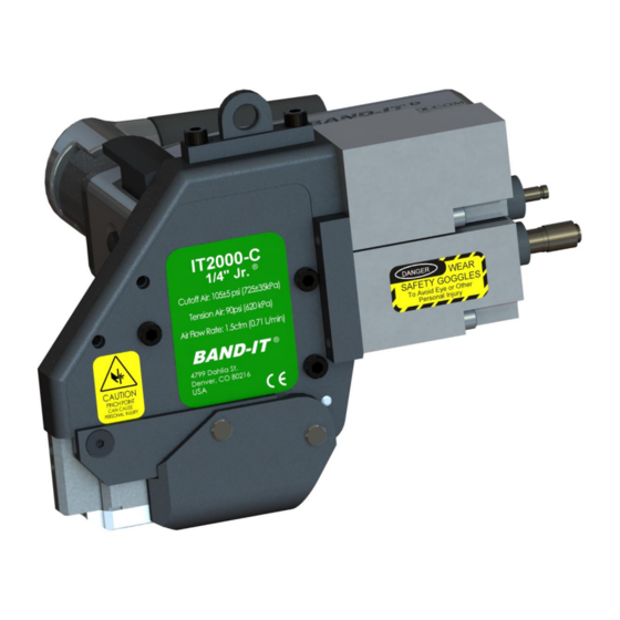
IT1000-C / IT2000-C
®
Pneumatic IT Tools
www.BAND-IT-IDEX.com
Page 1 of 36
IT1000-C / IT2000-C
1/4" IT Tool
Document # P49050 Rev. C
© Copyright
BAND-IT-IDEX, Inc. 2015
All rights reserved
Advertisement

Related Manuals for Band-it IT1000-C


Summary of Contents for Band-it IT1000-C
- Page 1 Operating IT1000-C / IT2000-C Manual 1/4” IT Tool IT1000-C / IT2000-C 1/4” BAND-IT ® Pneumatic IT Tools Original document (not a translation) BAND-IT-IDEX, Inc. Document # P49050 Rev. C A Unit of IDEX Corporation © Copyright www.BAND-IT-IDEX.com 4799 Dahlia Street BAND-IT-IDEX, Inc.
- Page 2 Operating IT1000-C / IT2000-C Manual 1/4” IT Tool Topic Page Description Page # 3 – 4 Safety Safety Guidelines Tool Overview Introduction Options Review & Model Identification 7 – 8 Tool / Component Identification Air System Requirements Air System 10-11...
-
Page 3: Safety Guidelines
1/4” IT Tool Safety Guidelines This equipment has been tested by BAND-IT-IDEX and meets the requirement of stability during use, storage conditions, transportation, assembly, dismantling when out of service, testing or foreseeable breakdowns providing that the proper safety precautions are observed. - Page 4 Operating IT1000-C / IT2000-C Manual 1/4” IT Tool Safety Guidelines Environmental operating conditions are defined as: • For Indoor Use ONLY • Temperature range from 5°C to 38°C • Max relative humidity 80% for temperatures up to 31°C. Allowable humidity then decreases linearly to 50% at 38°C...
-
Page 5: Tool Overview
Operating IT1000-C / IT2000-C Manual 1/4” IT Tool Tool Overview This machine is designed to automatically install clamps with repeatability and control. • The tool consists of a tension system and a cutting system, both pneumatically controlled. • The pneumatic system can be adjusted to provide appropriate clamp force for different applications. - Page 6 Operating IT1000-C / IT2000-C Manual 1/4” IT Tool IT Tool Options • Any IT tool can be ordered as a stand alone tool or with accessories. Accessories packages all include a pneumatic air flow regulator. Additional accessories vary depending on the tool options.
- Page 7 Operating IT1000-C / IT2000-C Manual 1/4” IT Tool Tool / Component Identification Operating Trigger Handle Cover Handle Quick Connect Air Couplings (Do not add lubricants) Tool Tension Reset Cylinder Cut-Off Cylinder Tool Mounting Serial # Locations Location Tool Body Tool Head with...
- Page 8 Operating IT1000-C / IT2000-C Manual 1/4” IT Tool Identification of Standard Accessories Coiled Air Lines Air Regulator Module Packaging Option 0: Box includes IT tool, owners manual, air controller module, coiled air line, hex keys and fittings Packaging Option 1: Box includes the IT tool and manual only BAND-IT-IDEX, Inc.
- Page 9 The BAND-IT Air Controller Module includes a filter to meet particle requirements. BAND-IT recommends the use of an Air Booster System to address the potential problems associated with low air supply, including: •filters and dries the air supply...
- Page 10 Operating IT1000-C / IT2000-C Manual 1/4” IT Tool Air Control Regulator Assembly (I56099) 1/8” Quick Disconnects Connect tool air hoses Air Shut-Off Valve Air Supply 100-150 psi Quick Disconnect Comes with “Industrial” installed, also supplied with Tru-Flate fitting. Alternatively connect with Muffler any ¼”...
- Page 11 Operating IT1000-C / IT2000-C Manual 1/4” IT Tool Regulator Mounting Holes For proper performance the air control module must be mounted and operated in a horizontal position as shown on the previous page. Below is the layout for the mounting hole locations dimensioned in inches.
- Page 12 Connect Air Controller Module to air source (assure air supply meets requirements on “Air System Requirements” page) and turn RED Shut-off Valve to pressurize tool (supply position). IT2000-C / 1/4” JR IT1000-C / 1/4” Tie-Lok ® ® Clamps Ties...
- Page 13 Operating IT1000-C / IT2000-C Manual 1/4” IT Tool ® ® Tie-Lok Tie / Jr Clamp Installation Procedure (Tie-Lok Tie only) Lace the tie snug around the assembly and locate the buckle in the target location. Band should be applied to a uniform solid...
- Page 14 1/4” IT Tool IT Tool Orientation Requirements The BAND-IT Pneumatic IT Tool must be used correctly in order to reliably install a clamp. Part of ensuring that the tool is producing a strong lock is making sure that it approaches the application correctly and the fixture configuration allows repeatability of application.
- Page 15 IT1000-C / IT2000-C Manual 1/4” IT Tool Tie / Clamp Inspection The IT1000-C forms a locking dimple into the Tie-Lok tie with the punch and cuts the remaining tail. When installing a Tie-Lok tie, a visual check is recommended to verify the presence of a locking dimple after the tie has been applied.
- Page 16 Do not install clamps on tapered surfaces or on tube bends • Tie-Lok & JR Clamp advised min installed diameter is 1” For specific questions contact BAND-IT-IDEX Customer Service at 1-800-525-0758 or 303-320-4555 for more information. BAND-IT-IDEX, Inc. Document # P49050 Rev. C A Unit of IDEX Corporation ©...
- Page 17 Do not bring tool up to stop for positioning. A stop will not allow proper tool rotation during tension and cutoff resulting in a loss of clamp performance For specific questions contact BAND-IT-IDEX Customer Service at 1-800-525-0758 or 303-320-4555 for more information.
- Page 18 Operating IT1000-C / IT2000-C Manual 1/4” IT Tool Dimple Clip Guide (IT1000 only) • The dimple clip provides a full depth punch during a the cutoff cycle. The dimple clip also helps to reduce the occurrence of undetectable loose ties. The presence of the punch provides a positive visual indicator to identify good vs.
- Page 19 Operating IT1000-C / IT2000-C Manual 1/4” IT Tool Adjustable Handle for Hand Use • Using a hex key (supplied), adjust the handle to ergonomically match the operators hand. • Be sure not to adjust the handle too far outward (beyond interlocking legs) or the handle will not function properly or provide support to the operator.
- Page 20 Operating IT1000-C / IT2000-C Manual 1/4” IT Tool IT Tool Clearance Requirements There are three common considerations for tool clearance Channel Flat width (D) • Must be wider than the blade (A) 0.76” [19.3mm] Raised width (E) • Must be wider than flip cover (B) 1.38” [35.1mm] when between 0.23”...
- Page 21 Manual 1/4” IT Tool Fixture Hanger At a minimum BAND-IT recommends that the tool be connected to a weight balancer or be mounted in a fixture that will provide adequate rotation during operation. • Support boom & Balancer • 4 axis of movement...
- Page 22 Operating IT1000-C / IT2000-C Manual 1/4” IT Tool Fixture Mounting Holes Three additional fixture mounting holes are available to assist with mounting the tool. Thread size is M5 for all holes. One hole is utilized to attach and lock the tool body cover to the tool body.
- Page 23 2-way & 3-way valves included below. The valve should be set up in the normally closed mode and upon opening the circuit a supply of air is provided. • The customer is responsible for incorporating this tool into their process. BAND-IT-IDEX is available to provide advice and recommendations. Remote trigger: 2-way valve...
- Page 24 Mounting Hole: ½”-14 NPT .85” diameter clearance hole for ½”-14 lock nut Electrical components are rated: IP67 Contact BAND-IT IDEX Customer Service at 1-800-525-0758 or 303-320-4555 for any questions not addressed above. BAND-IT-IDEX, Inc. Document # P49050 Rev. C A Unit of IDEX Corporation ©...
- Page 25 Operating IT1000-C / IT2000-C Manual 1/4” IT Tool Trouble Shooting Guide: Unable to Achieve Tension If the tool fails to fully tension the clamp: Failure to fully tension the clamp can be caused by a variety of factors. The two most common factors are incorrect tension pressure and problems with the grippers.
- Page 26 Do not allow fixture interference with tool For JR/ IT2000,check that proper motion. blade is installed . Contact BAND-IT-IDEX Customer Service at 1-800-525-0758 or 303-320-4555 for repair on any issues not addressed above. BAND-IT-IDEX, Inc. Document # P49050 Rev. C A Unit of IDEX Corporation ©...
-
Page 27: Preventative Maintenance
BAND-IT for service. Pneumatic components must be serviced by BAND-IT in order to assure proper tool performance after a repair. Clamps... -
Page 28: Maintenance Replacement Parts
Several fasteners require Loctite, Blue - Medium strength. Please have both the tool model and serial numbers available when calling the factory for service or assistance. Contact BAND-IT-IDEX Customer Service at 1-800-525-0758 or 303-320-4555 for more information. Part numbers are subject to change. - Page 29 Operating IT1000-C / IT2000-C Manual 1/4” IT Tool Maintenance: Maintenance Cover Important: Before disassembling tool, be sure to shut-off air supply on the Control Module. Note: This tool uses metric fasteners. 1) Remove the two e-style retaining rings and two clevis pins.
- Page 30 Operating IT1000-C / IT2000-C Manual 1/4” IT Tool Maintenance: Tension Block Inspection & Replacement Disassembly & Inspection: Remove the two Compression Springs. Remove Tension Gripper and Tension Block pin from the Tension Block. Tension Gripper — Look for worn spots or other damage.
- Page 31 Operating IT1000-C / IT2000-C Manual 1/4” IT Tool Maintenance: Cutter Blade Inspection & Replacement Removal & Installation: Remove the four M3x8 screws with a 2.5mm hex key. This can occur with the tool fully assembled. Pull the cutter blade off of the two alignment pins in the tool head.
- Page 32 Operating IT1000-C / IT2000-C Manual 1/4” IT Tool Maintenance: Tool Body and Linkages 1) Remove the three cap screws (4mm hex) and the one flat head screw (3mm hex) as shown. 2) Remove the side cover after screws are removed. The side cover is a close fit and may require a screwdriver to pry off near the tension arm.
- Page 33 Push the pin out of knife assembly to remove the cutter arm Inspect cutting edge for chips and excessive wear. Make sure knife is well lubricated. For IT1000-C only: the Dimple Pin height should be 0.105” minimum. Inspect dimple pin for excessive wear.
-
Page 34: Maintenance: Lubrication
Lubricate tool cavity as shown with red arrows below. Also, lubricate the inside surfaces of the maintenance cover (shown below). BAND-IT recommends lubrication every 25,000 clamps. Dirty environments may require more frequent intervals. Inspect all mechanical linkages for lubrication and proper placement. Refit cover. - Page 35 Operating IT1000-C / IT2000-C Manual 1/4” IT Tool Maintenance: Cutoff Timing Adjustment Remove the two cap screws in the Handle Cover with a 4mm hex key. Remove cover and lay aside during their removal. The valve used to adjust timing is highlighted in the picture below.
- Page 36 Tool sales may include up to 12 month limited warranty. Limited meaning that wear parts are not included, such as blades and grippers. • BAND-IT must be given the opportunity to physically examine all warranty claims. • Tools found with severe abuse or unapproved modifications may void warranty upon BAND-IT’s discretion.
Need help?
Do you have a question about the IT1000-C and is the answer not in the manual?
Questions and answers