JRC JMA-7133-SA Instruction Manual
Marine radar equipment
Hide thumbs
Also See for JMA-7133-SA:
- Brochure (8 pages) ,
- Installation manual (316 pages) ,
- Simplified manual (24 pages)
Table of Contents
Advertisement
Quick Links
Advertisement
Chapters
Table of Contents
Troubleshooting

Related Manuals for JRC JMA-7133-SA


Summary of Contents for JRC JMA-7133-SA
- Page 1 JMA-7133-SA JMA-7133-SA JMA-7132-SA JMA-7132-SA JMA-7123-7XA/9XA JMA-7123-7XA/9XA JMA-7122-6XA/9XA/6XAH JMA-7122-6XA/9XA/6XAH JMA-7110-6XA/6XAH JMA-7110-6XA/6XAH MARINE RADAR MARINE RADAR EQUIPMENT EQUIPMENT INSTRUCTION INSTRUCTION MANUAL MANUAL...
- Page 3 ◆◆◆ PRECAUTIONS BEFORE OPERATION ◆◆◆ ■ Cautions for high voltage High voltages from hundreds volts to tens of thousands volts are to be applied to the electronic equipment such radio and radar devices. You do not face any danger during normal operation, but sufficient cares are required for maintenance, inspection and adjustment of their internal components.
- Page 4 ◆◆◆ FIRST-AID TREATMENTS ◆◆◆ ☆ First-aid treatments As far as the victim of electric shock is not in dangerous condition, do not move him and practice artificial respiration on him immediately. Once started, it should be continued rhythmically. Do not touch the victim confusedly as a result of the accident, but the rescuer may also get an electric shock.
- Page 5 ☆ When pulse is beating but breathing has stopped (Mouth-to-mouth respiration) Fig 1. Tilt the victim's head back as far as this face looks back. (A pillow may be inserted his neck.) Push his jaw upward to open his throat wide (to spread his airway). Pinch the victim's nostrils and take a deep breath, block his mouth completely with yours and blow into his mouth strongly.
- Page 6 ☆ When both pulse and breathing have stopped Perform the (Cardiac massage) Fig 2. and (Mouth-to-mouth respiration) Fig 1. When no pulse has come not to be felt, his pupils are open and no heartbeat is heard, cardiac arrest is supposed to have occurred and artificial respiration must be performed.
-
Page 7: Preface
PREFACE Thank you very much for purchasing the JRC marine radar equipment, JMA-7100 series. This equipment is a marine radar equipment designed to obtain safe operation of marine ships. This equipment consists of a radar signal transmitter-receiver unit, a LCD display unit and a scanner unit as its main units. - Page 8 ● Before Operation ● Pictorial Indication Various pictorial indications are included in this manual and are shown on these equipment so that you can operate them safety and correctly and prevent any danger to you and/or to other persons and any damage to your property during operation.
- Page 9 ● PRECAUTIONS ● Never conduct inspection or repair work of equipment components. Inspection or repair work by uncertified personnel may result in fire hazard or electrocution. For inspection and repair work of equipment components, consult with our branch office, branch shop, sales office, or our distributor in your district.
- Page 10 Make sure to turn off the scanner safety switch. Failure to comply may result in injuries caused by physical contact with the rotating scanner. Never directly touch the internal components of the scanner or indicator. Direct contact with these high- voltage components may cause electrocution.
- Page 11 Microwave radiation level: Keep away from a scanner when it is transmitting. The high level of microwave is radiated from the front face of the scanner specified below. The microwave exposure at close range could result in injuries (especially of the eyes). Microwave radiation level System 50 W/m 10 W/m...
- Page 12 When cleaning the display screen, do not wipe it too strongly with a dry cloth. Also, do not use gasoline or thinner to clean the screen. Failure to comply will result in damage to the screen surface. Do not change MBS Level/Area unless absolutely necessary.
- Page 13 Use Target Tracking (TT) function only as a navigation aid. The final navigation decision must always be made by the operator him/herself. Making the final navigation decision based only on tracking target information may cause accidents. Tracking target information such as vector, target numerical data, and alarms may contain some errors.
- Page 14 When setting a guard zone, make sure to properly adjust gain, sea-surface reflection suppression level, and rain/ snow reflection suppression level so that the optimal target images are always on the radar screen. The guard zone alarm will not be activated for targets undetected by the radar, and it may result in accidents such as collisions.
- Page 15 Make sure to take off your watch when your hand must get close to the magnetron. Failure to comply may result in damage to the watch since the magnetron is a strong magnet. Make sure that two or more staff member work together when replacing the LCD.
- Page 16 Do not change the quantization level settings unless absolutely necessary. If set at an inappropriate value, the target acquisition or target tracking function deteriorates, and this may lead to accidents.
-
Page 17: The Mounting Point Of The Warning Label
The Mounting Point of the Warning Label Warning Label NCD-4790 Display Unit Warning Label Front face Back face NWZ-173 LCD Monitor... - Page 18 Warning Label NDC-1399-7 Radar Process Unit (Desktop Type) Warning Label NBA-5135 AC/DC Converter (Desktop Type)
- Page 19 Warning Label NQE-3141-4A/8A Interswitch Unit Warning Label NQE-3167 Power Control Unit xvii...
- Page 20 Warning Label NKE-2103-6/6HS Scanner Unit Warning Label NKE-1129-7/9 Scanner Unit NKE-1125-6/9 Scanner Unit NKE-2254-6HS Scanner Unit xviii...
- Page 21 Warning Label NKE-1139/1130 Scanner Unit Warning Label NTG-3230/3225 Transmitter Receiver Unit...
-
Page 22: Equipment Appearance
EQUIPMENT APPEARANCE Scanner Unit Type NKE-1130 (12 feet) Scanner Unit Type NKE-1139 (12 feet) Transmitter Receiver Unit Type NTG-3230(30kW) - Page 23 Scanner Unit Type NKE-1129-7 (7 feet) Scanner Unit Type NKE-1129-9 (9 feet) Transmitter Receiver Unit Type NTG-3225(25kW)
- Page 24 Scanner Unit Type NKE-1125-6 (6 feet) Scanner Unit Type NKE-1125-9 (9 feet) Scanner Unit Type NKE-2254-6HS (6 feet) xxii...
- Page 25 Scanner Unit Type NKE-2103-6 (6 feet) Scanner Unit Type NKE-2103-6HS (6 feet) Power Control Unit Type NQE-3167 xxiii...
- Page 26 Display Unit Type NCD-4790 (Stand alone type) Interswitch Unit Type NQE-3141-4A xxiv...
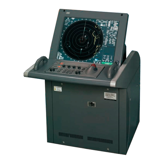
- Page 27 Monitor Unit Type NWZ-173 (Desktop type) Operation Unit Type NCE-5163 (Desktop type) Radar Process Unit Type NDC-1399-7 (Desktop type) DISPLAY UNIT TYPE NCD-4790T (DESKTOP TYPE)
-
Page 28: Glossary
GLOSSARY This section describes the main terms used for this equipment and general related maritime terms. Acquisition/Activation zone A zone set up by the operator in which the system should automatically acquire radar targets and activate reported AIS targets when entering the zone. Activated target A target representing the automatic or manual activation of a sleeping target for the display of additional information. - Page 29 CPA/TCPA The distance to the Closest Point of Approach/Time to the Closest Point of Approach. Limits are set by the operator and are related to own ship. Course Through Water The direction of the ship's movement through the water DRIFT The current velocity for manual correction or the current speed on the horizontal axis of the 2-axis log is displayed.
- Page 30 Lost AIS target A target symbol representing the last valid position of an AIS target before the reception of its data was lost, or its last dead-reckoned position. Lost tracked One for which target information is no longer available due to poor, lost or obscured signals.
- Page 31 Relative Motion A display on which the position of own ship remains fixed, and all targets move relative to own ship. RM(R) Relative Motion. Relative Trails. RM(T) Relative Motion. True Trails. Rate Of Turn Change of heading per time unit. Route A set of waypoints.
- Page 32 Trial manoeuvre A graphical simulation facility used to assist the operator to perform a proposed maneuver for navigation and collision avoidance purposes. True course The direction of motion relative to ground or to sea, of a target expressed as an angular displacement from north True speed The speed of a target relative to ground, or to sea True vector...
-
Page 33: Table Of Contents
Index ◆◆◆ PRECAUTIONS BEFORE OPERATION ◆◆◆ ..........i ◆◆◆ FIRST-AID TREATMENTS ◆◆◆ ..............ii PREFACE ........................v The Mounting Point of the Warning Label ..............xv EQUIPMENT APPEARANCE ................... xx GLOSSARY ......................xxvi SECTION 1 GENERAL AND EQUIPMENT COMPOSITION FUNCTIONS ...................1-1 1.1.1 Function of This System ..............1-1 FEATURES .....................1-2... - Page 34 3.2.6 Suppress Rain/Snow Clutter [RAIN] ...........3-11 3.2.7 Reset Alarm Buzzer [ALARM ACK] ..........3-12 3.2.8 ...3-13 To get the appropriate image that targets can be easily observed OPERATION PROCEDURES ..............3-14 3.3.1 Move Cross Cursor Mark by Trackball ........3-14 3.3.2 Operate Software Buttons ............3-15 3.3.3 Basic Menu Operation ..............3-16 3.3.4...
- Page 35 3.5.8 Use Water Temperature Track (Water TEMP Track) ....3-45 3.5.9 Use Tidal Current Track (Current Vector Track) ......3-46 DISPLAY USER MAP ................3-47 3.6.1 Create User Map (Mark/Line) ............3-47 3.6.2 Set User Map Display (Mark Display Setting) ......3-50 3.6.3 Edit User Map (Edit User Map) .............3-52 3.6.4 Correct Position on User Map (Shift User Map) ......3-60 3.6.5...
- Page 36 3.10.2 Load Operating State (Load User Setting) ........3-120 3.10.3 Delete Operating State (Delete User Setting) ......3-120 3.11 USING CARD ..................3-121 3.11.1 Operate File on the Card (File Manager) ........3-121 3.12 RECEIVE PORT SETTING ..............3-128 3.12.1 Receive Port Setting (RX Port) ..........3-128 SECTION 4 MEASUREMENT OF RANGE AND BEARING USE OF NAVIGATION TOOLS ..............4-1...
- Page 37 5.2.4 Displaying Target ID No.(Target Number Display) .....5-19 5.2.5 Adding Tracked Target ID Name (Name) ........5-20 5.2.6 Reference Target (Reference) ............5-21 5.2.7 Operation Test (TT Test Menu) ...........5-22 AIS OPERATION ..................5-27 5.3.1 Restrictions ..................5-27 5.3.2 Setting AIS Display Function (AIS Function) ......5-27 5.3.3 Activate AIS Targets (Activate AIS) ..........5-28 5.3.4...
- Page 38 SECTION 6 TRUE AND FALSE ECHOES ON DISPLAY RADAR WAVE WITH THE HORIZON ...........6-1 STRENGTH OF REFLECTION FROM THE TARGET ......6-3 SEA CLUTTER AND RAIN AND SNOW CLUTTER ......6-5 FALSE ECHOES ..................6-9 DISPLAY OF RADAR TRANSPONDER (SART) ........6-12 DISPLAY OF AIS-SART ...............6-14 6.6.1 Display ...................6-14 6.6.2...
- Page 39 ROUTINE MAINTENANCE ..............8-1 MAINTENANCE ON EACH UNIT ............8-2 8.2.1 Scanner Unit NKE-1125/1129/1130/1139/2103/2254 ....8-2 8.2.2 Flexible wave guide (JMA-7123-7XA/9XA) ........8-4 8.2.3 Coaxial Cable (JMA-7133-SA) ............8-4 8.2.4 Transmitter Receiver Unit (NTG-3225/3230) ........8-5 8.2.5 Display Unit (NCD-4790) ..............8-5 PERFORMANCE CHECK ..............8-6 8.3.1 Check Performance on Test Menu ..........8-7 REPLACEMENT OF MAJOR PARTS ..........8-13...
- Page 40 DISPOSAL OF USED MAGNETRON ..........10-2 10.4 DISPOSAL OF TR-TUBE ..............10-2 10.5 ABOUT THE CHINA ROHS ..............10-3 SECTION 11 SPECIFICATION 11.1 JMA-7133-SA TYPE RADAR ...............11-1 11.2 JMA-7132-SA TYPE RADAR ............... 11-2 11.3 JMA-7123-7XA/9XA TYPE RADAR ............11-3 11.4 JMA-7122-6XA/9XA TYPE RADAR ............11-4 11.5 JMA-7122-6XAH TYPE RADAR ............11-5...
- Page 41 11.19 AIS FUNCTION ...................11-21 11.20 PERFORMANCE MONITOR (NJU-84) ..........11-22 11.21 PERFORMANCE MONITOR (NJU-85) ..........11-22 11.22 AC/DC CONVERTER (NBA-5135) .............11-22 Appendix A NQE-3141 Interswitch Unit OVERVIEW .................... A-1 A.1.1 Overview ..................A-1 A.1.2 Interswitch Setup ................A-1 INTERSWITCH OPERATION ..............A-3 A.2.1 Operation Flow ................
- Page 42 JMA-7122-6XAH (desktop) ............B-36 B.7.5 JMA-7122-6XA/9XA ..............B-37 B.7.6 JMA-7123-7XA/9XA ..............B-38 B.7.7 JMA-7132-SA ................B-39 B.7.8 JMA-7133-SA ................B-40 B.7.9 NCD-4790T ..................B-41 GYRO I/F ..................... B-42 Inter Switch Unit ................. B-44 B.9.1 Terminal Board Connection Diagram ......... B-44 B.9.2...
- Page 43 Appendix C Menu Index Main ....................... C-1 PI ......................C-5 TT ......................C-7 AIS ......................C-8 AZ ......................C-9 Track ....................C-10 Route ....................C-11 U.Map ....................C-12 Serviceman Menu ................C-14...
- Page 45 Modified March 2, 2011 19:17 GENERAL AND EQUIPMENT COMPOSITION NAMES AND FUNCTIONS OF CONTROL PANEL KEYS AND FUNCTIONS OF SOFTWARE BUTTONS BASIC OPERATION MEASUREMENT OF RANGE AND BEARING OPERATION OF TARGET TRACKING AND AIS TRUE AND FALSE ECHOES ON DISPLAY SETTINGS FOR SYSTEM OPERATION COUNTERMEASURES FOR TROUBLE AND ADJUSTMENT...
-
Page 47: General And Equipment Composition
SECTION 1 GENERAL AND EQUIPMENT COMPOSITION GENERAL AND EQUIPMENT COMPOSITION FUNCTIONS ...................1-1 1.1.1 Function of This System ..............1-1 FEATURES .....................1-2 CONFIGURATION ..................1-4 EXTERIOR DRAWINGS .................1-6 GENERAL SYSTEM DIAGRAMS ............1-25... -
Page 49: Functions
> > JMA-7100 Instruction Manual 1.GENERAL AND EQUIPMENT COMPOSITION 1.1 FUNCTIONS FUNCTIONS This equipment is a high-performance radar equipment consisting of a scanner unit, a transmitter-receiver unit and a high resolution color LCD display unit. This equipment complies with the performance standard of IMO. 1.1.1 Function of This System The JMA-7100 series is a color radar system designed to comply with the... -
Page 50: Features
JMA-7100 Instruction Manual > 1.GENERAL AND EQUIPMENT COMPOSITION > 1.2 FEATURES FEATURES Realization of Large, Easy-to-see Screen with High Resolution The 19-inch color LCD with high resolution of 1280 1024 pixels can display radar images of 250 mm or more in diameter. Even short-range targets can also be displayed as high-resolution images. - Page 51 JMA-7100 Instruction Manual > 1.GENERAL AND EQUIPMENT COMPOSITION > 1.2 FEATURES Improved Day/Night Mode Five types of background colors are available in Day/Dusk/Night mode (total 5 background colors). Each background color can be reproduced to be suited for the user's operating environment by simple key operation. The radar echoes and a variety of graphics can also be represented in different colors, ensuring easy-to- see displays.
-
Page 52: Configuration
CONFIGURATION Table1-1:Specified of scanner, and categories of ship/craft for SOLAS V Type of Radar Antenna type Transmitted Band Rate of Category Output Power rotation JMA-7133-SA 12ft Slotted Antenna 30kW 24rpm CAT 2 JMA-7132-SA 12ft Slotted Antenna 30kW 24rpm CAT 2... - Page 53 Radar Process Unit NDC-1399-7 Operation Unit NCE-5163 In JMA-7123, the following type name of JRC is used for the flexible wave guide between the scanner unit and the transmitter receiver unit. Type of Radar Waveguide Length(m) Type name of JRC...
-
Page 54: Exterior Drawings
JMA-7100 Instruction Manual > 1.GENERAL AND EQUIPMENT COMPOSITION > 1.4 EXTERIOR DRAWINGS EXTERIOR DRAWINGS Fig 1-1: Outline Drawing of Scanner Unit, Type NKE-1139 Fig 1-2: Outline Drawing of Scanner Unit, Type NKE-1130 Fig 1-3: Outline Drawing of Scanner Unit, Type NKE-1129-7 Fig 1-4: Outline Drawing of Scanner Unit, Type NKE-1129-9 Fig 1-5: Outline Drawing of Scanner Unit, Type NKE-1125-6 Fig 1-6: Outline Drawing of Scanner Unit, Type NKE-1125-9... - Page 55 JMA-7100 Instruction Manual > 1.GENERAL AND EQUIPMENT COMPOSITION > 1.4 EXTERIOR DRAWINGS Fig 1-1: Outline Drawing of Scanner Unit, Type NKE-1139 1- 7...
- Page 56 JMA-7100 Instruction Manual > 1.GENERAL AND EQUIPMENT COMPOSITION > 1.4 EXTERIOR DRAWINGS Fig 1-2: Outline Drawing of Scanner Unit, Type NKE-1130 1- 8...
- Page 57 JMA-7100 Instruction Manual > 1.GENERAL AND EQUIPMENT COMPOSITION > 1.4 EXTERIOR DRAWINGS Fig 1-3: Outline Drawing of Scanner Unit, Type NKE-1129-7 1- 9...
- Page 58 JMA-7100 Instruction Manual > 1.GENERAL AND EQUIPMENT COMPOSITION > 1.4 EXTERIOR DRAWINGS Fig 1-4: Outline Drawing of Scanner Unit, Type NKE-1129-9 1- 10...
- Page 59 JMA-7100 Instruction Manual > 1.GENERAL AND EQUIPMENT COMPOSITION > 1.4 EXTERIOR DRAWINGS Fig 1-5: Outline Drawing of Scanner Unit, Type NKE-1125-6 1- 11...
- Page 60 JMA-7100 Instruction Manual > 1.GENERAL AND EQUIPMENT COMPOSITION > 1.4 EXTERIOR DRAWINGS Fig 1-6: Outline Drawing of Scanner Unit, Type NKE-1125-9 1- 12...
- Page 61 JMA-7100 Instruction Manual > 1.GENERAL AND EQUIPMENT COMPOSITION > 1.4 EXTERIOR DRAWINGS Fig 1-7: Outline Drawing of Scanner Unit, Type NKE-2254-6HS 1- 13...
- Page 62 JMA-7100 Instruction Manual > 1.GENERAL AND EQUIPMENT COMPOSITION > 1.4 EXTERIOR DRAWINGS Fig 1-8: Outline Drawing of Scanner Unit, Type NKE-2103-6/6HS 1- 14...
- Page 63 JMA-7100 Instruction Manual > 1.GENERAL AND EQUIPMENT COMPOSITION > 1.4 EXTERIOR DRAWINGS Fig 1-9: Outline Drawing of Transmitter Receiver Unit, Type NTG-3230 1- 15...
- Page 64 JMA-7100 Instruction Manual > 1.GENERAL AND EQUIPMENT COMPOSITION > 1.4 EXTERIOR DRAWINGS Fig 1-10: Outline Drawing of Transmitter Receiver Unit, Type NTG-3225 1- 16...
- Page 65 JMA-7100 Instruction Manual > 1.GENERAL AND EQUIPMENT COMPOSITION > 1.4 EXTERIOR DRAWINGS Fig 1-11: Outline Drawing of Display Unit, Type NCD-4790 1- 17...
- Page 66 JMA-7100 Instruction Manual > 1.GENERAL AND EQUIPMENT COMPOSITION > 1.4 EXTERIOR DRAWINGS Fig 1-12: Outline Drawing of Monitor Unit, Type NWZ-173 (Desktop type option) 1- 18...
- Page 67 JMA-7100 Instruction Manual > 1.GENERAL AND EQUIPMENT COMPOSITION > 1.4 EXTERIOR DRAWINGS Fig 1-13: NDOutline Drawing of Radar Process Unit, Type NDC-1399-7 (Desktop type option) 1- 19...
- Page 68 JMA-7100 Instruction Manual > 1.GENERAL AND EQUIPMENT COMPOSITION > 1.4 EXTERIOR DRAWINGS Fig 1-14: Outline Drawing of Operation Unit, Type NCE-5163 (Desktop type option) 1- 20...
- Page 69 JMA-7100 Instruction Manual > 1.GENERAL AND EQUIPMENT COMPOSITION > 1.4 EXTERIOR DRAWINGS Fig 1-15: Outline Drawing of AC/DC Converter, Type NBA-5135 (Desktop type option) 1- 21...
- Page 70 JMA-7100 Instruction Manual > 1.GENERAL AND EQUIPMENT COMPOSITION > 1.4 EXTERIOR DRAWINGS Fig 1-16: Outline Drawing of Interswitch Unit, Type NQE-3141-4A (Option) 1- 22...
- Page 71 JMA-7100 Instruction Manual > 1.GENERAL AND EQUIPMENT COMPOSITION > 1.4 EXTERIOR DRAWINGS Fig 1-17: Outline Drawing of Interswitch Unit, Type NQE-3141-8A (Option) 1- 23...
- Page 72 JMA-7100 Instruction Manual > 1.GENERAL AND EQUIPMENT COMPOSITION > 1.4 EXTERIOR DRAWINGS Fig 1-18: Outline Drawing of Power Control Unit, Type NQE-3167 (Option) 1- 24...
-
Page 73: General System Diagrams
> > JMA-7100 Instruction Manual 1.GENERAL AND EQUIPMENT COMPOSITION 1.5 GENERAL SYSTEM DIAGRAMS GENERAL SYSTEM DIAGRAMS Fig 1-20: General System Diagram of Radar, Type JMA-7132-SA Fig 1-21: General System Diagram of Radar, Type JMA-7123-7XA Fig 1-22: General System Diagram of Radar, Type JMA-7123-9XA Fig 1-23: General System Diagram of Radar, Type JMA-7122-6XA Fig 1-24: General System Diagram of Radar, Type JMA-7122-9XA Fig 1-25: General System Diagram of Radar, Type JMA-7122-6XAH... - Page 74 250 V -T T YCS - 4 Fig 1-19: General System Diagram of Radar, Type JMA-7133-SA Eliminating the interference on frequencies used for marine communications and navigation due to operation of the radar. All cables of the radar are to be run away from the cables of radio equipment.(Ex.
- Page 75 JMA-7100 Instruction Manual > 1.GENERAL AND EQUIPMENT COMPOSITION > 1.5 GENERAL SYSTEM DIAGRAMS NKE-1130 SCANNER UNIT NJU-84 PERFORMANCE CIRCUIT BREAKER MONITOR (SHIP YARD SUPPLY) O P T I O N (5A) AC100 V,50/60Hz 1φ,200 W ( W I T H P M U N I T) 0.
- Page 76 JMA-7100 Instruction Manual > 1.GENERAL AND EQUIPMENT COMPOSITION > 1.5 GENERAL SYSTEM DIAGRAMS NKE-1129-7 SCANNER UNIT NJU-85 PERFORMANCE CIRCUIT BREAKER MONITOR (SHIP YARD SUPPLY) O P T I O N (5A) AC100V,50/60Hz 1φ100W ( W I T H P M U N I T) 0 .
- Page 77 JMA-7100 Instruction Manual > 1.GENERAL AND EQUIPMENT COMPOSITION > 1.5 GENERAL SYSTEM DIAGRAMS NKE-1129-9 SCANNER UNIT NJU-85 PERFORMANCE CIRCUIT BREAKER MONITOR (SHIP YARD SUPPLY) O P T I O N (5A) AC100V,50/60Hz 1φ,100W ( W I T H P M U N I T) 0 .
- Page 78 JMA-7100 Instruction Manual > 1.GENERAL AND EQUIPMENT COMPOSITION > 1.5 GENERAL SYSTEM DIAGRAMS NKE-1125-6 SCANNER UNIT NJU-85 PERFORMANCE CIRCUIT BREAKER MONITOR (SHIP YARD SUPPLY) O P T I O N (5A) AC100V,50/60Hz 1φ,100W ( W I T H P M U N I T) 0 .
- Page 79 JMA-7100 Instruction Manual > 1.GENERAL AND EQUIPMENT COMPOSITION > 1.5 GENERAL SYSTEM DIAGRAMS NKE-1125-9 SCANNER UNIT NJU-85 PERFORMANCE CIRCUIT BREAKER MONITOR (SHIP YARD SUPPLY) O P T I O N (5A) AC100V,50/60Hz 1φ,100W ( W I T H P M U N I T) 0 .
- Page 80 JMA-7100 Instruction Manual > 1.GENERAL AND EQUIPMENT COMPOSITION > 1.5 GENERAL SYSTEM DIAGRAMS NKE-2254-6HS SCANNER UNIT NJU-85 PERFORMANCE CIRCUIT BREAKER MONITOR (SHIP YARD SUPPLY) O P T I O N (5A) AC100V,50/60Hz 1φ,100W ( W I T H P M U N I T) 0 .
- Page 81 JMA-7100 Instruction Manual > 1.GENERAL AND EQUIPMENT COMPOSITION > 1.5 GENERAL SYSTEM DIAGRAMS NKE-2103-6 SCANNER UNIT NJU-85 PERFORMANCE MONITOR 1 9 C O R E S C O M P O S I T E C A B L E 65 m MA X C F Q - 6 9 1 2- * * M A X 1 4 .
- Page 82 JMA-7100 Instruction Manual > 1.GENERAL AND EQUIPMENT COMPOSITION > 1.5 GENERAL SYSTEM DIAGRAMS NKE-2103-6HS SCANNER UNIT NJU-85 PERFORMANCE MONITOR 1 9 C O R E S C O M P O S I T E C A B L E 65m MAX C F Q - 6 9 1 2- * * M A X 1 4 .
-
Page 83: Names And Functions Of Control Panel Keys And Functions Of
SECTION 2 NAMES AND FUNCTIONS OF CONTROL PANEL KEYS AND FUNCTIONS OF SOFTWARE BUTTONS NAMES AND FUNCTIONS OF CONTROL PANEL KEYS AND FUNCTIONS OF SOFTWARE BUTTONS NAMES OF DISPLAY ................2-1 NAMES AND FUNCTIONS OF CONTROL PANEL KEYS ....2-11 FUNCTIONS OF SOFTWARE BUTTONS ...........2-16... -
Page 85: Names Of Display
> > JMA-7100 Instruction Manual 2.CONTROL PANEL KEYS and SOFTWARE BUTTONS 2.1 NAMES OF DISPLAY NAMES OF DISPLAY Example of screen display In this example, the screen is divided into a number of areas and the names in each area are indicated. Upper left Upper right of the display... - Page 86 > > JMA-7100 Instruction Manual 2.CONTROL PANEL KEYS and SOFTWARE BUTTONS 2.1 NAMES OF DISPLAY Automatic acquisition / Association target Own ship's symbol activation zone Ship's heading marker Past position Ship's heading line AIS target number Cursor mark AIS target symbol Tracked target vector Tracked target...
- Page 87 > > JMA-7100 Instruction Manual 2.CONTROL PANEL KEYS and SOFTWARE BUTTONS 2.1 NAMES OF DISPLAY Upper left of the display Range scale Tuning indication Range rings display On / Off Range rings interval Transmission pulse length Motion mode true / relative Radar trail true / relative Stability mode Off center...
- Page 88 > > JMA-7100 Instruction Manual 2.CONTROL PANEL KEYS and SOFTWARE BUTTONS 2.1 NAMES OF DISPLAY Upper right of the display Cursor bearing Cursor bearing Cursor mode numeric value indication Cursor latitude true / relative Cursor range Cursor longitude EBL1 numeric value indication EBL1 true / relative starting point mode...
- Page 89 > > JMA-7100 Instruction Manual 2.CONTROL PANEL KEYS and SOFTWARE BUTTONS 2.1 NAMES OF DISPLAY About time display mode UTC : Universal Time Coordinate UTC(S) : UTC (System Time) LMT : Local Mean Time LMT (S) : LMT (System Time) Target tracking (TT) / AIS information Target tracking (TT) / Target vector true / relative...
- Page 90 > > JMA-7100 Instruction Manual 2.CONTROL PANEL KEYS and SOFTWARE BUTTONS 2.1 NAMES OF DISPLAY Numeric information: AIS target information AIS target number Simple display item Ship's name Unread message Call sign MMSI Course Speed TCPA Bearing Ship's heading bearing Rate of turn Range Latitude...
- Page 91 > > JMA-7100 Instruction Manual 2.CONTROL PANEL KEYS and SOFTWARE BUTTONS 2.1 NAMES OF DISPLAY Numeric information: Enhancement of cursor position numeric value indication Cursor bearing numeric Cursor bearing value indication true / relative Cursor range Cursor latitude Cursor longitude Numeric information: Enhancement of EBL / VRM numeric value display EBL bearing EBL bearing...
- Page 92 > > JMA-7100 Instruction Manual 2.CONTROL PANEL KEYS and SOFTWARE BUTTONS 2.1 NAMES OF DISPLAY Graph information: Depth indication Depth Depth range Depth graph Time range Graph information: Water temperature indication Water temperature Water temperature range Water temperature graph Time range Graph information: Wind direction / speed Wind direction / speed true / relative...
- Page 93 > > JMA-7100 Instruction Manual 2.CONTROL PANEL KEYS and SOFTWARE BUTTONS 2.1 NAMES OF DISPLAY Graph information: Course bar Auto pilot course Ship's heading bearing Rudder Rate of turn Numeric information: Marker Marker bearing Marker latitude Marker range Marker longitude Arrival time Menu Main menu...
- Page 94 > > JMA-7100 Instruction Manual 2.CONTROL PANEL KEYS and SOFTWARE BUTTONS 2.1 NAMES OF DISPLAY Brilliance Main menu Digital information Parallel index line menu Automatic acquisition / Target Tracking (TT) menu activation zone (AZ) menu Own Track menu User map menu AIS menu Route menu Display information...
-
Page 95: Names And Functions Of Control Panel Keys
> > JMA-7100 Instruction Manual 2.CONTROL PANEL KEYS and SOFTWARE BUTTONS 2.2 NAMES AND FUNCTIONS OF CONTROL PANEL KEYS NAMES AND FUNCTIONS OF CONTROL PANEL KEYS The name of each button is described from the following page. See below. 2- 11... - Page 96 > > JMA-7100 Instruction Manual 2.CONTROL PANEL KEYS and SOFTWARE BUTTONS 2.2 NAMES AND FUNCTIONS OF CONTROL PANEL KEYS [POWER] (Power supply) switch The lamp is lit and the equipment is activated. If this switch is pressed while the equipment is running, the power of the equipment is shut down.
- Page 97 > > JMA-7100 Instruction Manual 2.CONTROL PANEL KEYS and SOFTWARE BUTTONS 2.2 NAMES AND FUNCTIONS OF CONTROL PANEL KEYS [GAIN] (Gain/pulse length) dial This function adjusts the reception sensitivity of the radar. To increase the sensitivity, turn the dial clockwise. The transmission pulse width can be switched by pressing the dial.
- Page 98 > > JMA-7100 Instruction Manual 2.CONTROL PANEL KEYS and SOFTWARE BUTTONS 2.2 NAMES AND FUNCTIONS OF CONTROL PANEL KEYS [VRM] (Variable Range Marker) dial This function changes the range of the VRM that is selected by VRM1/2. By pressing the dial, the parallel line cursor function can be switched to Operation → Fixed →...
- Page 99 > > JMA-7100 Instruction Manual 2.CONTROL PANEL KEYS and SOFTWARE BUTTONS 2.2 NAMES AND FUNCTIONS OF CONTROL PANEL KEYS [DATA OFF] (DATA Off) key This function sets the graphics other than HL, range ring, EBL, and VRM to OFF temporarily while this key is pressed. →...
-
Page 100: Functions Of Software Buttons
> > JMA-7100 Instruction Manual 2.CONTROL PANEL KEYS and SOFTWARE BUTTONS 2.3 FUNCTIONS OF SOFTWARE BUTTONS FUNCTIONS OF SOFTWARE BUTTONS In this radar, the frequently used functions can be directly set from the screen without opening the menu by using the software buttons on the screen for quick handling. - Page 101 > > JMA-7100 Instruction Manual 2.CONTROL PANEL KEYS and SOFTWARE BUTTONS 2.3 FUNCTIONS OF SOFTWARE BUTTONS Upper left of the display ① Range scale switching ② Range rings display ⑦ Transmission pulse length On /Off switching ③ Motion mode true / relative switching ④...
- Page 102 > > JMA-7100 Instruction Manual 2.CONTROL PANEL KEYS and SOFTWARE BUTTONS 2.3 FUNCTIONS OF SOFTWARE BUTTONS Interswitch connection change This button is displayed when the interswitch is connected. This button indicates the connection status of the scanner unit that is connected to the indicator. If the button is clicked in the transmission standby state, the menu for changing the connection state between the scanner unit and the indicator is displayed.
- Page 103 > > JMA-7100 Instruction Manual 2.CONTROL PANEL KEYS and SOFTWARE BUTTONS 2.3 FUNCTIONS OF SOFTWARE BUTTONS Interference rejection (IR) mode switching The interference rejection mode is switched whenever this button is clicked. IR Off IR Low IR Meddle IR High IR Off ⇒...
- Page 104 > > JMA-7100 Instruction Manual 2.CONTROL PANEL KEYS and SOFTWARE BUTTONS 2.3 FUNCTIONS OF SOFTWARE BUTTONS Upper Right of the display ⑨ EBL1 numeric value indication ② Mark font / line pattern true / relative switching switching ① Cursor mode switching ③...
- Page 105 > > JMA-7100 Instruction Manual 2.CONTROL PANEL KEYS and SOFTWARE BUTTONS 2.3 FUNCTIONS OF SOFTWARE BUTTONS EBL1 / 2 and VRM1 / 2 adjustment These functions set the EBL1 , VRM1 , EBL2 , and VRM2 displays to On / Off and acquire the operation right.
- Page 106 > > JMA-7100 Instruction Manual 2.CONTROL PANEL KEYS and SOFTWARE BUTTONS 2.3 FUNCTIONS OF SOFTWARE BUTTONS Lower right of the display ③ Own ship's track interval switching ① Mark color switching ④ Own ship's track interval unit switching ② Own ship’s track color switching ⑤...
- Page 107 > > JMA-7100 Instruction Manual 2.CONTROL PANEL KEYS and SOFTWARE BUTTONS 2.3 FUNCTIONS OF SOFTWARE BUTTONS CPA ring display On / Off The CPA ring display is switched to On / Off whenever the button is clicked. When the target vector display mode is (true vector), the CPA ring cannot be set to Own ship's information ①...
- Page 108 > > JMA-7100 Instruction Manual 2.CONTROL PANEL KEYS and SOFTWARE BUTTONS 2.3 FUNCTIONS OF SOFTWARE BUTTONS Target tracking (TT) / AIS information ① Target vector display ② Target vector length setting ④ TCPA limit setting true / relative switching ⑥ Past position display ③...
- Page 109 > > JMA-7100 Instruction Manual 2.CONTROL PANEL KEYS and SOFTWARE BUTTONS 2.3 FUNCTIONS OF SOFTWARE BUTTONS Past position display interval switching The past position display interval is switched whenever the button is clicked. Past position display interval unit switching The past position display interval unit is switched whenever the button is clicked. ⇒...
- Page 110 > > JMA-7100 Instruction Manual 2.CONTROL PANEL KEYS and SOFTWARE BUTTONS 2.3 FUNCTIONS OF SOFTWARE BUTTONS Numeric information: AIS target information simple display ①:Detail / simple display switching ②:Unread message display Detail / simple display switching This function switches the display mode to detail / simple display when AIS target information is displayed.
- Page 111 > > JMA-7100 Instruction Manual 2.CONTROL PANEL KEYS and SOFTWARE BUTTONS 2.3 FUNCTIONS OF SOFTWARE BUTTONS Numeric information: Tracked target information ① Tracked target numeric value indication scroll Tracked target numeric value indication scroll This function scrolls the target numbers that are indicated in the tracked target information.
- Page 112 > > JMA-7100 Instruction Manual 2.CONTROL PANEL KEYS and SOFTWARE BUTTONS 2.3 FUNCTIONS OF SOFTWARE BUTTONS Graph information: Wind direction / speed ① Wind direction / speed numeric value indication true / relative switching Wind direction / speed numeric value indication true / relative switching The wind direction / speed numeric value indication is switched to (true) /...
- Page 113 > > JMA-7100 Instruction Manual 2.CONTROL PANEL KEYS and SOFTWARE BUTTONS 2.3 FUNCTIONS OF SOFTWARE BUTTONS AIS menu If the button is clicked, the AIS Menu is opened. Route menu If this button is clicked, the Route Menu is opened. Parallel index line menu If this button is clicked, the PI Menu is opened.
- Page 114 > > JMA-7100 Instruction Manual 2.CONTROL PANEL KEYS and SOFTWARE BUTTONS 2.3 FUNCTIONS OF SOFTWARE BUTTONS Display item switching The brilliance adjustment screen and display information setting screen interchange whenever this button is clicked. ⇔ Panel lighting brilliance switching This function enables the setting of the brilliance of the lighting of the control panel. The brilliance changes whenever this button is clicked.
- Page 115 > > JMA-7100 Instruction Manual 2.CONTROL PANEL KEYS and SOFTWARE BUTTONS 2.3 FUNCTIONS OF SOFTWARE BUTTONS Alarm ① Alarm acknowridgement ② Error log display Alarm acknowledgment If this button is clicked, the buzzer sound of the alarm that is currently issued is stopped and the alarm lamp stops blinking.
- Page 116 > > JMA-7100 Instruction Manual 2.CONTROL PANEL KEYS and SOFTWARE BUTTONS 2.3 FUNCTIONS OF SOFTWARE BUTTONS 2- 32...
-
Page 117: Basic Operation
SECTION 3 BASIC OPERATION BASIC OPERATION OPERATION FLOW ................3-1 3.1.1 Power ON and Start the System ............3-2 3.1.2 Observe and Adjust Video ..............3-4 3.1.3 Acquire and Measure Data .............3-4 3.1.4 Display and Measure with Reference to CCRP ......3-4 3.1.5 End the Operation and Stop the System ........3-5 OBSERVE AND ADJUST VIDEO ............3-6 3.2.1 Adjust Monitor Brilliance [BRILL] ..........3-6... - Page 118 OPERATION PROCEDURES ..............3-14 3.3.1 Move Cross Cursor Mark by Trackball ........3-14 3.3.2 Operate Software Buttons ............3-15 3.3.3 Basic Menu Operation ..............3-16 3.3.4 Operation on Numeric Value, Latitude / Longitude and Character Input menu ..................3-17 3.3.5 Overview of Menu Structure ............3-22 GENERAL RADAR OPERATION ............3-23 3.4.1 Interference Rejection (IR) ............3-23...
- Page 119 USE ROUTE FUNCTION ..............3-67 3.7.1 Display Route/Destination Mark (Select Route) ......3-67 3.7.2 Edit Route (Set Route Sequence) ..........3-68 3.7.3 Edit Route Make with Latitude and Longitude .3-75 (Waypoint Input) 3.7.4 Use Route Monitoring Function (Waypoint/Route Alarm) ..3-79 3.7.5 Method of Using Route ..............3-81 3.7.6 Detailed Route Settings ..............3-82 3.7.7...
-
Page 121: Operation Flow
> > JMA-7100 Instruction Manual 3.BASIC OPERATION 3.1 OPERATION FLOW OPERATION FLOW Attention • Do not put anything on the operation panel. If you put anything hot on it, it may be deformed. • Do not give any impact to the operation panel, trackball, or controls. -
Page 122: Power On And Start The System
> > JMA-7100 Instruction Manual 3.BASIC OPERATION 3.1 OPERATION FLOW 3.1.1 Power ON and Start the System • A malfunction may occur if the power in the ship is instantaneously interrupted during operation of the radar. In this case, the power should be turned on again. - Page 123 > > JMA-7100 Instruction Manual 3.BASIC OPERATION 3.1 OPERATION FLOW Procedures Check that the ship’s mains are turned on. Press [POWER] key. The system is turned on, and the preheating time is displayed. Preheat is indicated at the upper left of the radar display. Wait until the preheating time is over.
-
Page 124: Observe And Adjust Video
> > JMA-7100 Instruction Manual 3.BASIC OPERATION 3.1 OPERATION FLOW 3.1.2 Observe and Adjust Video Procedures Press [RANGE+] key or [RANGE-] key to set the range to the scale required for target observation. [GAIN] [SEA] and [RAIN] to obtain the clearest targets. Refer to [GAIN] dial→... -
Page 125: End The Operation And Stop The System
> > JMA-7100 Instruction Manual 3.BASIC OPERATION 3.1 OPERATION FLOW 3.1.5 End the Operation and Stop the System Exit Press [TX/STBY] key. The radar will stop transmission and the antenna will stop rotating. Transmit Standby at the upper left of the radar display changes to Maintain the standby state if radar observation is restarted in a relatively short time.Only pressing the [TX/STBY] key starts observation. -
Page 126: Observe And Adjust Video
> > JMA-7100 Instruction Manual 3.BASIC OPERATION 3.2 OBSERVE AND ADJUST VIDEO OBSERVE AND ADJUST VIDEO 3.2.1 Adjust Monitor Brilliance [BRILL] Procedures Obtain the best-to-see display with optimum brilliance by turning the [BRILL] dial at the lower right of the monitor unit. Turning the [BRILL] dial clockwise increases the brilliance of the entire display. -
Page 127: Tune
> > JMA-7100 Instruction Manual 3.BASIC OPERATION 3.2 OBSERVE AND ADJUST VIDEO 3.2.3 Tune Normally, use the automatic tune mode. Use the manual tune mode only when best tuning is not possible in the automatic tune mode due to deterioration of magnetron. This radar system provides the automatic tune mode and the manual tune mode. -
Page 128: Adjust Gain [Gain]
> > JMA-7100 Instruction Manual 3.BASIC OPERATION 3.2 OBSERVE AND ADJUST VIDEO 3.2.4 Adjust Gain [GAIN] If the gain is too high, unnecessary signals including receiver noise and false images increase resulting in reduction of visibility of targets. On the contrary, if the gain is too low, targets including ships and dangerous objects may not be clearly indicated. -
Page 129: Suppress Sea Clutter [Sea]
> > JMA-7100 Instruction Manual 3.BASIC OPERATION 3.2 OBSERVE AND ADJUST VIDEO 3.2.5 Suppress Sea Clutter [SEA] When using the sea clutter suppression function, never set the suppression level too high canceling out all image noises from the sea surface at close range. Detection of not only echoes from waves but also targets such as other ships or dangerous objects will become inhibited. - Page 130 > > JMA-7100 Instruction Manual 3.BASIC OPERATION 3.2 OBSERVE AND ADJUST VIDEO 3.2.5.2 Using the automatic sea clutter suppression mode The sea clutter suppression in accordance with the intensity of sea clutter is possible. Use this mode when the sea clutter's intensity differs according to directional orientation.
-
Page 131: Suppress Rain/Snow Clutter [Rain]
> > JMA-7100 Instruction Manual 3.BASIC OPERATION 3.2 OBSERVE AND ADJUST VIDEO 3.2.6 Suppress Rain/Snow Clutter [RAIN] When using the rain clutter suppression function, never set the suppression level too high canceling out all image noises from the rain or snow at the close range. -
Page 132: Reset Alarm Buzzer [Alarm Ack]
> > JMA-7100 Instruction Manual 3.BASIC OPERATION 3.2 OBSERVE AND ADJUST VIDEO 3.2.6.2 Using the automatic rain / snow clutter suppression mode The rain / snow clutter suppression in accordance with the intensity of rain / snow clutter is possible. Use this mode when the rain / snow clutter's intensity differs according to directional orientation. -
Page 133: To Get The Appropriate Image That Targets Can Be Easily Observed
> > JMA-7100 Instruction Manual 3.BASIC OPERATION 3.2 OBSERVE AND ADJUST VIDEO 3.2.8 To get the appropriate image that targets can be easily observed To get the appropriate image that targets can be easily observed which requires an understanding for RADAR signal processing features and an adjustment for the sea state. -
Page 134: Operation Procedures
> > JMA-7100 Instruction Manual 3.BASIC OPERATION 3.3 OPERATION PROCEDURES OPERATION PROCEDURES 3.3.1 Move Cross Cursor Mark by Trackball The cross cursor mark + is used for position designation and other purposes in various operating procedures. The cross cursor mark + moves in coupling with the trackball. -
Page 135: Operate Software Buttons
> > JMA-7100 Instruction Manual 3.BASIC OPERATION 3.3 OPERATION PROCEDURES 3.3.2 Operate Software Buttons Software buttons are provided on the radar display so as to easily switch functions without operating menu items. For software buttons that can be operated and their locations, see Section 2.3 "FUNCTIONS OF SOFTWARE BUTTONS". -
Page 136: Basic Menu Operation
> > JMA-7100 Instruction Manual 3.BASIC OPERATION 3.3 OPERATION PROCEDURES 3.3.3 Basic Menu Operation 3.3.3.1 To open the menu By left-clicking the Main button located at the lower right of the radar display, the main menu will open By left-clicking the buttons, , and , adjacent to Main... -
Page 137: Operation On Numeric Value, Latitude / Longitude And Character Input Menu
> > JMA-7100 Instruction Manual 3.BASIC OPERATION 3.3 OPERATION PROCEDURES 3.3.3.7 Menu Operation with the Trackball Item Selected item Press numeric keys corresponding to the desired item number to display the Present state selected item. Press numeric keys corresponding to the desired item number to Cursor select a set value. - Page 138 > > JMA-7100 Instruction Manual 3.BASIC OPERATION 3.3 OPERATION PROCEDURES 3.3.4.1 Numeric value input screen Entered value Numeric button - button + button Clear button Enter button 3.3.4.2 Directly entering a numeric value Procedures On the numeric value input screen, sequentially left-click the software number keys located on the radar screen, and enter a desired numeric value.
- Page 139 > > JMA-7100 Instruction Manual 3.BASIC OPERATION 3.3 OPERATION PROCEDURES 3.3.4.3 Increasing or decreasing a numeric value Procedures On the numeric value input screen, sequentially left-click the software button located on the radar screen, and + - enter a desired numeric value. For example, when adjusting 123.0°...
- Page 140 > > JMA-7100 Instruction Manual 3.BASIC OPERATION 3.3 OPERATION PROCEDURES 3.3.4.5 Entering latitude/longitude Procedures On the latitude/longitude input screen, sequentially click numeric buttons to enter latitude (XX°XX.XXX'). For example, to enter 12°34.567', sequentially click numeric buttons as follows. → → →...
- Page 141 A to Z, numbers from 0 to 9, or symbols (only comments for mark/line), and then left-click the ENT button to enter one character of the name to be inputted. For example, JRC for a name, click button as follows: → →...
-
Page 142: Overview Of Menu Structure
> > JMA-7100 Instruction Manual 3.BASIC OPERATION 3.3 OPERATION PROCEDURES 3.3.5 Overview of Menu Structure The menu structure of this radar system consists of eight frequently used function menus, one main menu, and one service man menu used for the installation settings. -
Page 143: General Radar Operation
> > JMA-7100 Instruction Manual 3.BASIC OPERATION 3.4 GENERAL RADAR OPERATION GENERAL RADAR OPERATION 3.4.1 Interference Rejection (IR) Interference by other radars is rejected. Attention • When viewing a radar beacon or SART signal, select IR Off (Interference Rejector OFF) because IR processing suppresses the video. -
Page 144: Switch Transmitter Pulse Length [Gain]
> > JMA-7100 Instruction Manual 3.BASIC OPERATION 3.4 GENERAL RADAR OPERATION 3.4.2 Switch Transmitter Pulse Length [GAIN] Procedures Press [GAIN] dial Values of the transmitter pulse width are switched. Effects of transmitter pulse width With selected: The transmitter pulse becomes shorter, and the range resolution improves. -
Page 145: Target Enhance (Enh)
> > JMA-7100 Instruction Manual 3.BASIC OPERATION 3.4 GENERAL RADAR OPERATION 3.4.3 Target Enhance (ENH) The dimension of video display is enlarged to enhance a target. Procedures Left-click the ENH button located at the lower left of the radar display. The target enlargement levels are switched. -
Page 146: Use Video Processing (Proc)
> > JMA-7100 Instruction Manual 3.BASIC OPERATION 3.4 GENERAL RADAR OPERATION 3.4.4 Use Video Processing (PROC) This function reduces unnecessary noise to highlight targets. Attention • When viewing a radar beacon, SART signal, or fast moving target on the radar display, select PROC Off (video process off). -
Page 147: Switch Azimuth Display Mode (Azi Mode)
> > JMA-7100 Instruction Manual 3.BASIC OPERATION 3.4 GENERAL RADAR OPERATION 3.4.5 Switch Azimuth Display Mode (AZI MODE) Select the bearing for the radar video to be displayed on the radar display. Procedures Left-click the AZI Mode button located at the lower left of the display. -
Page 148: Switch True/Relative Motion Display Mode (Tm/Rm)
> > JMA-7100 Instruction Manual 3.BASIC OPERATION 3.4 GENERAL RADAR OPERATION 3.4.6 Switch True/Relative Motion Display Mode (TM/RM) 3.4.6.1 Switching Relative Motion (RM) Mode to True Motion (TM) Mode Procedures Left-click the motion mode button located at the upper left of the radar display. -
Page 149: Move Own Ship's Display Position (Off Center)
> > JMA-7100 Instruction Manual 3.BASIC OPERATION 3.4 GENERAL RADAR OPERATION 3.4.7 Move Own Ship’s Display Position (Off Center) The own ship’s position can be moved from the display center to any position within 66% of the display radius. This function is convenient for observing a wide coverage in any direction. -
Page 150: Display Radar Trails (Trails)
> > JMA-7100 Instruction Manual 3.BASIC OPERATION 3.4 GENERAL RADAR OPERATION 3.4.8 Display Radar Trails (Trails) Other ship's movements and speeds can be monitored from the lengths and directions of their trails, serving for collision avoidance. The trail length varies according to setting. - Page 151 > > JMA-7100 Instruction Manual 3.BASIC OPERATION 3.4 GENERAL RADAR OPERATION 3.4.8.3 Trails Motion Mode There are two types of trails: relative motion trails and true motion trails. Relative motion The system plots the trails of a target at a position relative to trails: the own ship.
- Page 152 > > JMA-7100 Instruction Manual 3.BASIC OPERATION 3.4 GENERAL RADAR OPERATION 3.4.8.4 Changing Motion Mode of Trails (Trails Mode) Procedures Click the Trails Mode located at the upper right of the radar display. RADAR trails true/relative The trails motion modes are switched. ⇔...
-
Page 153: Zoom (X2)
> > JMA-7100 Instruction Manual 3.BASIC OPERATION 3.4 GENERAL RADAR OPERATION 3.4.9 Zoom (x2) This function doubles the size of radar video near a specified position. NOTE: If the range is 0.125 NM , this function is not available. Procedures Left-click the x2 button located at the lower left of the display. -
Page 154: Hide/Display Range Rings [Hl Off]
> > JMA-7100 Instruction Manual 3.BASIC OPERATION 3.4 GENERAL RADAR OPERATION 3.4.10 Hide/Display Range Rings [HL OFF] Procedures Press the [HL OFF] key. Alternatively, Left-click the button located at the lower right of the display. The ship's heading line (HL) is hidden while the [HL OFF] key is held down. The ship's heading line that indicates the course of own ship is always shown on the radar display. -
Page 155: Switch Day/Night Mode [Day/Night]
> > JMA-7100 Instruction Manual 3.BASIC OPERATION 3.4 GENERAL RADAR OPERATION 3.4.12 Switch Day/Night Mode [DAY/NIGHT] Several combinations of the display color and brilliance according to the ambient lighting conditions are provided. The display color setting is easily changed. Procedures Press the [DAY/NIGHT] key. -
Page 156: Set True Bearing
> > JMA-7100 Instruction Manual 3.BASIC OPERATION 3.4 GENERAL RADAR OPERATION 3.4.14 Set True Bearing When the GYRO I/F is used to enter a gyro signal, there is a rare case in which a true bearing value indicated by the master gyro does not match the true bearing value indicated by this radar system. -
Page 157: Magnet Compass Correction (Mag Compass Setting)
> > JMA-7100 Instruction Manual 3.BASIC OPERATION 3.4 GENERAL RADAR OPERATION NOTE: •If the single axis water log display can present the speed of the ship in other than the forward direction, the direction of movement should be indicated unambiguously. Therefore single axis water logs cannot detect the effect of leeway. - Page 158 > > JMA-7100 Instruction Manual 3.BASIC OPERATION 3.4 GENERAL RADAR OPERATION Set whether to make corrections or not. 1. Heading Correction ⇔ Input the correction value. + - Press the button to select south and north for latitude or the east and west for longitude.
-
Page 159: Use Own Ship's Track
> > JMA-7100 Instruction Manual 3.BASIC OPERATION 3.5 USE OWN SHIP'S TRACK USE OWN SHIP'S TRACK The own ship's track function saves and displays own ship's track. If navigation equipment is connected, this radar system records latitude/longitude data sent from the navigation equipment and displays own ship's track. NOTE: Even when own ship's track storage interval is turned , own ship's track can be displayed. -
Page 160: Set Display Color Of Own Ship's Track (Display Own Track Color)
> > JMA-7100 Instruction Manual 3.BASIC OPERATION 3.5 USE OWN SHIP'S TRACK The map display function is turned on or off When Color is selected, the own ship's track is displayed. 3.5.2 Set Display Color of Own Ship's Track (Display Own Track Color) Own ship's track can be saved in seven different colors. -
Page 161: Save Own Ship's Track (Own Track Memory)
> > JMA-7100 Instruction Manual 3.BASIC OPERATION 3.5 USE OWN SHIP'S TRACK 3.5.3 Save Own Ship's Track (Own Track Memory) To save own ship's track, storage at a specified time interval and at a specified range interval can be selected. The track storage interval can be selected from 10 preset time intervals and 8 preset range intervals. -
Page 162: Clear Own Ship's Track (Clear Own Track)
> > JMA-7100 Instruction Manual 3.BASIC OPERATION 3.5 USE OWN SHIP'S TRACK 3.5.5 Clear Own Ship's Track (Clear Own Track) This function cancels the storing of own ship's track. Procedures Open the Clear Own Track Color menu by performing the menu operation below. - Page 163 > > JMA-7100 Instruction Manual 3.BASIC OPERATION 3.5 USE OWN SHIP'S TRACK Procedures Left-click the button located at the lower right of the Track display. Track menu The Own Track Menu will appear. Left-click the item button of 3. Track Type The numeric value of the navigation data can be shown by the color of own ship's track.
-
Page 164: Use Water Depth Track (Water Depth Track)
> > JMA-7100 Instruction Manual 3.BASIC OPERATION 3.5 USE OWN SHIP'S TRACK 3.5.7 Use Water Depth Track (Water Depth Track) Set the corresponding conditions for the water depth value and the color of own ship's track by performing the operation below. Procedures Open the Water Depth Setting menu by performing the menu operation below. -
Page 165: Use Water Temperature Track (Water Temp Track)
> > JMA-7100 Instruction Manual 3.BASIC OPERATION 3.5 USE OWN SHIP'S TRACK 3.5.8 Use Water Temperature Track (Water TEMP Track) Set the corresponding conditions for the water temperature value and the color of own ship's track by performing the operation below. Procedures Open the Water TEMP. -
Page 166: Use Tidal Current Track (Current Vector Track)
> > JMA-7100 Instruction Manual 3.BASIC OPERATION 3.5 USE OWN SHIP'S TRACK 3.5.9 Use Tidal Current Track (Current Vector Track) Set the conditions for adding tidal current vectors to own ship's track by performing the operation below. Procedures Open the Current Setting menu by performing the menu operation below. -
Page 167: Display User Map
> > JMA-7100 Instruction Manual 3.BASIC OPERATION 3.6 DISPLAY USER MAP DISPLAY USER MAP Up to 20,000 items of NAV lines, coastlines, depth contours, and NAV marks can be created, displayed, loaded, and saved. (This function is available only when navigation equipment is connected to this radar system.) Marks that can be used : 29 types Lines that can be used : 3 types (solid, broken, and dashed-dotted line) - Page 168 > > JMA-7100 Instruction Manual 3.BASIC OPERATION 3.6 DISPLAY USER MAP Left-click the mark font button to select a font for the □ mark. The mark fonts are switched. Left-click the button located to the right of the mark font to select a color for the mark.
- Page 169 > > JMA-7100 Instruction Manual 3.BASIC OPERATION 3.6 DISPLAY USER MAP Move the cursor to a desired location on the radar display and left-click. A line is plotted between the previous point and the end point. Repeat this procedure so that sequential lines can be plotted.
-
Page 170: Set User Map Display (Mark Display Setting)
> > JMA-7100 Instruction Manual 3.BASIC OPERATION 3.6 DISPLAY USER MAP Left-click the button to input the latitude / 3. L/L longitude. For the input method on the latitude / longitude input screen, see Section 3.3.4.5 "Entering latitude/longitude" Left-click the button to input the comment. - Page 171 > > JMA-7100 Instruction Manual 3.BASIC OPERATION 3.6 DISPLAY USER MAP The Display Mark Type menu will open. Specify whether to turn on or off the display for each type of mark and line. 1. All When is selected, the setting will reflect to all types of marks and lines. Off : All types are not displayed.
-
Page 172: Edit User Map (Edit User Map)
> > JMA-7100 Instruction Manual 3.BASIC OPERATION 3.6 DISPLAY USER MAP Specify the mark font size. Normal : The mark is displayed in normal size. Small : The mark is displayed in a size smaller than usual. 3.6.2.4 Setting the character size for comments Procedures Open the Comment Font Size menu by performing the menu operation below. - Page 173 > > JMA-7100 Instruction Manual 3.BASIC OPERATION 3.6 DISPLAY USER MAP Use the number buttons to enter a value of latitude (xx°xxx.xxx'). To make changes between north latitude and south latitude, use buttons. + - North latitude : Left-click the button.
- Page 174 > > JMA-7100 Instruction Manual 3.BASIC OPERATION 3.6 DISPLAY USER MAP The user map move mode is selected. Move Map is displayed in the cursor mode located at the upper right of the display. Put the cursor on a mark or line, and left-click. When a mark or line to be moved is selected, the cursor mark will appear.
- Page 175 > > JMA-7100 Instruction Manual 3.BASIC OPERATION 3.6 DISPLAY USER MAP 3.6.3.3 Deleting a mark or line (Delete) With regard to the created user map, a mark or line is deleted individually. Procedures Open the Edit User Map menu by performing the following menu operation.
- Page 176 > > JMA-7100 Instruction Manual 3.BASIC OPERATION 3.6 DISPLAY USER MAP 3.6.3.4 Inserting a vertex into a line (Insert/Move Vertex) With regard to the created user map, a vertex is inserted into a line. Procedures Open the Edit User Map menu by performing the following menu operation.
- Page 177 > > JMA-7100 Instruction Manual 3.BASIC OPERATION 3.6 DISPLAY USER MAP (Example) The side line into which a vertex is inserted Inserted vertex 3.6.3.5 Correcting the mark or vertex of a line (Insert/Move Vertex) With regard to the created user map, a mark or line is corrected. Procedures Open the Edit User Map menu by performing the following menu operation.
- Page 178 > > JMA-7100 Instruction Manual 3.BASIC OPERATION 3.6 DISPLAY USER MAP The cursor mode changes to the normal operation mode, terminating the user map insertion/correction mode. (Example) Original vertex New vertex 3.6.3.6 Deleting a mark or vertex from a line (Delete Vertex) With regard to the created user map, a vertex is deleted individually from a mark or line.
- Page 179 > > JMA-7100 Instruction Manual 3.BASIC OPERATION 3.6 DISPLAY USER MAP The cursor mode changes to the normal operation mode, terminating the user map delete mode. (Example) The vertex to be deleted 3.6.3.7 Batch clearing marks or lines (Clear) With regard to the created user map, marks or lines are batch cleared by type or by color. Procedures Open the Edit User Map menu by performing the following menu operation.
-
Page 180: Correct Position On User Map (Shift User Map)
> > JMA-7100 Instruction Manual 3.BASIC OPERATION 3.6 DISPLAY USER MAP Left-click the button. 1. Yes The selected mark will be deleted. NOTE: If data is not copied on the flash memory card (option), the data is not be reloaded. 3.6.4 Correct Position on User Map (Shift User Map) 3.6.4.1... -
Page 181: Save User Map
> > JMA-7100 Instruction Manual 3.BASIC OPERATION 3.6 DISPLAY USER MAP 3.6.4.2 Restoring the corrected user map to its original state (Shift Clear) Procedures Open the Mark Operations menu by performing the following menu operation. U.Map → 4. Shift Clear Only the most recently corrected data (for a single input) will be cleared, and the data will be displayed at its original position. - Page 182 > > JMA-7100 Instruction Manual 3.BASIC OPERATION 3.6 DISPLAY USER MAP Left-click the button. 3. Load The list of navigation data saved in the system will be displayed. Left-click the button for the file to be loaded. Confirmation Window will appear. Left-click the button.
- Page 183 > > JMA-7100 Instruction Manual 3.BASIC OPERATION 3.6 DISPLAY USER MAP Open the File Operations menu by performing the following menu operation. U.Map → 7. File Operation Left-click the item button of and select the 1. Select Card Slot card slot. Slot1 and Slot2 of the Select Card Slot items are switched.
- Page 184 > > JMA-7100 Instruction Manual 3.BASIC OPERATION 3.6 DISPLAY USER MAP Left-click the button. 6. Erase The Erace screen will appear. The list of navigation data saved in the card will be displayed. Click numeric buttons corresponding to the number for the file to be deleted.
-
Page 185: Set And Display Geodetic System (Geodetic)
> > JMA-7100 Instruction Manual 3.BASIC OPERATION 3.6 DISPLAY USER MAP 3.6.6 Set and Display Geodetic System (Geodetic) To create navigation information, set the geodetic system that is used with the connected navigation equipment. When navigation information is loaded, the geodetic system used when the navigation information was saved, is displayed. - Page 186 > > JMA-7100 Instruction Manual 3.BASIC OPERATION 3.6 DISPLAY USER MAP Table3-1: Geodetic System List # NAME 0 WGS-84 1 WGS-72 2 Japan 3 North American 1927(U.S) 4 North American 1927(Canada & Alaska) 5 European 1950 (Europe) 6 Australian geodetic 1966 (Australia) 7 Ordnance Survey of Great Britain (England) 8 NAD-83 9 - (No Use)
-
Page 187: Use Route Function
> > JMA-7100 Instruction Manual 3.BASIC OPERATION 3.7 USE ROUTE FUNCTION USE ROUTE FUNCTION In this radar system, a destination mark set by navigation equipment can be displayed, and a simple route can be created, displayed, loaded and saved. (To use this function, navigation equipment must be connected to this system) If radar video is poor visibility caused by route function, click the Map button to turn off the Map function. -
Page 188: Edit Route (Set Route Sequence)
> > JMA-7100 Instruction Manual 3.BASIC OPERATION 3.7 USE ROUTE FUNCTION 3.7.1.1 Displaying route created by the radar system (Internal) In this radar system, route created by the radar system are displayed as shown below. Planned Course 074T Route alarm line Waypoint 070T 12.5kn... - Page 189 > > JMA-7100 Instruction Manual 3.BASIC OPERATION 3.7 USE ROUTE FUNCTION Procedures Open the Set Route Sequence menu by performing the menu operation below. Route → 2. WPT/Route Setting → 3. Set Route Sequence Left-click the button. 7. New Monitor Route Confirmation Window will appear.
- Page 190 > > JMA-7100 Instruction Manual 3.BASIC OPERATION 3.7 USE ROUTE FUNCTION To add another Waypoint, repeat procedure 3. To finish adding a Waypoint, left-click twice at the last Waypoint. The Waypoint adding mode is cancelled. (Example) 062T 12.0kn Rubber band Last Waypoint 3.7.2.3 Correcting coordinates of a Waypoint (Correct Position)
- Page 191 > > JMA-7100 Instruction Manual 3.BASIC OPERATION 3.7 USE ROUTE FUNCTION Move the cursor to new coordinates, and left-click. The coordinates of the Waypoint are corrected, and then the Waypoint correcting mode is cancelled. (Example) 108T 108T 064T 064T 8.00kn 8.00kn 12.0kn 12.0kn...
- Page 192 > > JMA-7100 Instruction Manual 3.BASIC OPERATION 3.7 USE ROUTE FUNCTION On the radar display, put the cursor on the line extending between Waypoints that is to have its Planned Speed corrected. The section that is to have its Planned Speed corrected is specified, and the new Planned Speed is applied to the section.
- Page 193 > > JMA-7100 Instruction Manual 3.BASIC OPERATION 3.7 USE ROUTE FUNCTION On the radar display, put the cursor on a Waypoint to be deleted, and left-click. The specified Waypoint is deleted, and the previous and following Waypoints are then connected by a line. To delete another Waypoint, repeat procedure 3.
- Page 194 > > JMA-7100 Instruction Manual 3.BASIC OPERATION 3.7 USE ROUTE FUNCTION Left-click the button. 6. Insert The Waypoint inserting mode is selected. On the radar display, put the cursor on the section line into which a Waypoint is to be inserted, and left-click. The section is specified, the cursor becomes a cross cursor mark, and the cross cursor mark is connected to the previous and following Waypoints by a rubber band.
-
Page 195: Edit Route Make With Latitude And Longitude (Waypoint Input)
> > JMA-7100 Instruction Manual 3.BASIC OPERATION 3.7 USE ROUTE FUNCTION 3.7.3 Edit Route Make with Latitude and Longitude (Waypoint Input) In this radar system, it is possible to create and correct route by performing operation on the Waipoint Input menu. Waypoint Waypoint Number Waypoint Scroll... - Page 196 > > JMA-7100 Instruction Manual 3.BASIC OPERATION 3.7 USE ROUTE FUNCTION 3.7.3.2 Adding a Waypoint (Add) New Waypoint data is added to the route data saved in the radar system. Procedures Open the Waipoint Input menu. Left-click the button. The new latitude of waypoint is reversed. Enter a latitude / longitude and a planned speed.
- Page 197 > > JMA-7100 Instruction Manual 3.BASIC OPERATION 3.7 USE ROUTE FUNCTION 3.7.3.4 Correcting latitude / longitude of a Waypoint (LAT/LON) The latitude / longitude of a Waypoint in the route data saved in the radar system are corrected. Procedures Open the Waipoint Input menu. Left-click the Waypoint Scroll button.
- Page 198 > > JMA-7100 Instruction Manual 3.BASIC OPERATION 3.7 USE ROUTE FUNCTION 3.7.3.6 Deleting a Waypoint (DEL) The specified Waypoint in the route data saved in the radar system is deleted. Procedures Open the Waipoint Input menu. Left-click the Waypoint Scroll button. Left-click to show the desired waypoint.
-
Page 199: Use Route Monitoring Function (Waypoint/Route Alarm)
> > JMA-7100 Instruction Manual 3.BASIC OPERATION 3.7 USE ROUTE FUNCTION 3.7.4 Use Route Monitoring Function (Waypoint/Route Alarm) This radar system can monitor the movement of own ship with regard to its route and activate a variety of alarms. Destination alarm When own ship arrives at next Waypoint, an alarm will (Waypoint Alarm): be activated. - Page 200 > > JMA-7100 Instruction Manual 3.BASIC OPERATION 3.7 USE ROUTE FUNCTION Arrival Break Off : Set the operation mode. 0.00nm : Set the radius of the Waypoint alarm circle. If 0.00nm is set, alarm operation will be turned off. 3.7.4.2 Route Alarm The route alarm is activated when own ship deviates from the specified width of the route.
-
Page 201: Method Of Using Route
> > JMA-7100 Instruction Manual 3.BASIC OPERATION 3.7 USE ROUTE FUNCTION 3.7.5 Method of Using Route The method of using the route will be described. Displaying the route The internal route is displayed according to the procedures in (Route Alarm Color): Section 3.7.1 "Display Route/Destination Mark (Select Route)". -
Page 202: Detailed Route Settings
> > JMA-7100 Instruction Manual 3.BASIC OPERATION 3.7 USE ROUTE FUNCTION 3.7.5.2 Skipping/Back-skipping of the route (Waypoint Skip/ Waypoint Back Skip) Next Waypoint of the route can be changed by user manually. : Forward :Backward Skipping of route The Waypoint which is after the next Waypoint is set as the (Waypoint Skip): next Waypoint. - Page 203 > > JMA-7100 Instruction Manual 3.BASIC OPERATION 3.7 USE ROUTE FUNCTION Display character size :Specify the size of the numeric value and character displayed on the radar display. (SEL NUM/Comment Size) Waypoint bearing vector :Set the method to display line between next Waypoint and own ship.
- Page 204 > > JMA-7100 Instruction Manual 3.BASIC OPERATION 3.7 USE ROUTE FUNCTION 3.7.6.2 Display character size (SEL NUM/Comment Size) Specify the size of the numeric value and character displayed on the radar display. Procedures Open the Next menu by performing the menu operation below. Route → ...
- Page 205 > > JMA-7100 Instruction Manual 3.BASIC OPERATION 3.7 USE ROUTE FUNCTION 3.7.6.4 Displaying bearing distance to the Waypoint (Status of Origin/DEST) Select a start point used to display bearing/distance in the Waypoint data display area. Procedures Open the Next menu by performing the menu operation below. Route → ...
-
Page 206: Clear Waypoint/Route Data (Clear Wpt/Route Data)
> > JMA-7100 Instruction Manual 3.BASIC OPERATION 3.7 USE ROUTE FUNCTION 3.7.6.6 Updating Waypoint data (Waypoint Switch Mode) Set how to update the Waypoint number when one Waypoint has been reached. Procedures Open the WPT/Route Operations menu by performing the menu operation below. -
Page 207: Operate Route Data File
> > JMA-7100 Instruction Manual 3.BASIC OPERATION 3.7 USE ROUTE FUNCTION 3.7.8 Operate Route Data File Route data saved in the radar system can be saved onto a flash memory card, and data can be loaded from a flash memory card into the radar system. With regard to this item, only route data can be saved and loaded. - Page 208 > > JMA-7100 Instruction Manual 3.BASIC OPERATION 3.7 USE ROUTE FUNCTION 3.7.8.2 Saving route data (Save) Route data saved in the radar system is saved onto a flash memory card. Flash memory card (option) is necessary. Procedures Insert a flash memory card into the card slot. Open the File Operations menu by performing the menu operation below.
- Page 209 > > JMA-7100 Instruction Manual 3.BASIC OPERATION 3.7 USE ROUTE FUNCTION 3.7.8.3 Loading route data (Load) Route data is loaded into the radar system from a flash memory card. Flash memory card (option) is necessary. Once route data has been loaded into the radar system from a NOTE: flash memory card, the route data that has been saved in the radar system is overwritten and erased.
- Page 210 > > JMA-7100 Instruction Manual 3.BASIC OPERATION 3.7 USE ROUTE FUNCTION 3.7.8.4 Erasing route data (Erase) An unnecessary route data file saved on a flash memory card is erased. Flash memory card (option) is necessary. Once route data files that have been saved on a flash NOTE: memory card is erased, the erased data cannot be resaved.
-
Page 211: Applied Operations
> > JMA-7100 Instruction Manual 3.BASIC OPERATION 3.8 APPLIED OPERATIONS APPLIED OPERATIONS 3.8.1 Set Radar Signal Processing (Process Setting) This function enables the setting of detail information about radar signal processing. Procedures Open the Process Setting menu by performing the menu operation below. - Page 212 > > JMA-7100 Instruction Manual 3.BASIC OPERATION 3.8 APPLIED OPERATIONS 3.8.1.2 Video Noise Rejection • This function rejects signals that assumed as noise and clutter in radar videos. • Select to display radar videos like analog signals. • Select to suppress noise and clutter. Level1 Level2 •...
- Page 213 > > JMA-7100 Instruction Manual 3.BASIC OPERATION 3.8 APPLIED OPERATIONS 3.8.1.4 Process Switch • This function sets a specific area and switches the video process mode between the inside and outside of the area. • In Section 3.8.1.5 "2nd Porcess Mode" 2nd Process Mode, set the second video process mode for the area outside the boundary.
- Page 214 > > JMA-7100 Instruction Manual 3.BASIC OPERATION 3.8 APPLIED OPERATIONS 3.8.1.7 Fast Target Detection • This function displays fast moving targets that are suppressed in scan- correlative process mode. • 3Scan CORREL 4Scan CORREL This function is enabled when , or 5Scan CORREL is selected as the video process mode.
-
Page 215: Set Radar Trails (Radar Trails Setting)
> > JMA-7100 Instruction Manual 3.BASIC OPERATION 3.8 APPLIED OPERATIONS 3.8.2 Set Radar Trails (RADAR Trails Setting) This function enables the setting of detail information about radar trails processing. Procedures Open the RADAR Trails Setting menu by performing the menu operation below. - Page 216 > > JMA-7100 Instruction Manual 3.BASIC OPERATION 3.8 APPLIED OPERATIONS 3.8.2.3 Trails Reduction • Make a setting for thinning radar trails. • The effect of thinning increases in order of → → Level1 Level2 Level3 • Radar videos do not become obscure because of the thinning of radar trails. : Disables the Trails Reduction function.
-
Page 217: Set Scanner Unit (Txrx Setting)
> > JMA-7100 Instruction Manual 3.BASIC OPERATION 3.8 APPLIED OPERATIONS 3.8.3 Set Scanner Unit (TXRX Setting) This function enables the setting of detail information about an antenna. Procedures Open the TXRX Setting menu by performing the menu operation below. Main → ... -
Page 218: Set Cursor (Cursor Setting)
> > JMA-7100 Instruction Manual 3.BASIC OPERATION 3.8 APPLIED OPERATIONS 3.8.3.4 Ice Class Standby Mode • In this mode, the antenna is rotated when transmission is in the standby state. • This mode is effective to prevent the antenna's rotating shaft from freezing. :The ice class standby mode is not used. -
Page 219: Set Radar Display (Display Setting)
> > JMA-7100 Instruction Manual 3.BASIC OPERATION 3.8 APPLIED OPERATIONS 3.8.4.2 Cursor Length • Set the length of the cross cursor mark on the radar display. Short Cuts the cross cursor mark in length. Long : Makes the cross cursor mark twice as long as when Short is selected. - Page 220 > > JMA-7100 Instruction Manual 3.BASIC OPERATION 3.8 APPLIED OPERATIONS 3.8.5.2 Day/Night • Specify the mode to be changed. • The following modes are available: Day1 : Day mode 1 : Used under bright lighting conditions. Day2 : Day mode 2 : Used under bright lighting conditions.
- Page 221 > > JMA-7100 Instruction Manual 3.BASIC OPERATION 3.8 APPLIED OPERATIONS 3.8.5.3 Setting display brilliance (Brilliance Setting) For each Day/Night mode, background color outside the bearing scale, background color inside the bearing scale, and color for characters, radar echo and radar trails can be selected. Procedures Open the Brilliance Setting menu by performing the menu operation below.
- Page 222 > > JMA-7100 Instruction Manual 3.BASIC OPERATION 3.8 APPLIED OPERATIONS 3.8.5.4 Setting radar video brilliance (VID) The brilliance of the video on the radar display is adjusted. Procedures ○ Left-click the button located at the lower right of the radar display, and adjust the brilliance of the radar video so as to get the best view of the video display.
-
Page 223: Adjust Sound Volume (Buzzer Volume)
> > JMA-7100 Instruction Manual 3.BASIC OPERATION 3.8 APPLIED OPERATIONS 3.8.6 Adjust Sound Volume (Buzzer Volume) When an alarm is activated, the operation panel issues an alarm audible to inform user of the change of the condition. The alarm sound can be adjusted by performing the following procedures. Procedures Open the Buzzer Volume menu by performing the menu operation below. -
Page 224: Set User Option Keys [Option 1/2]
> > JMA-7100 Instruction Manual 3.BASIC OPERATION 3.8 APPLIED OPERATIONS 3.8.7 Set User Option Keys [OPTION 1/2] Users can freely make settings with [OPTION 1] key and [OPTION 2] key. By using the keys, users can open a frequently used menu by only single operation, or assign special functions, to the user key switches. - Page 225 > > JMA-7100 Instruction Manual 3.BASIC OPERATION 3.8 APPLIED OPERATIONS 3.8.7.2 Using Option Keys (Directly displaying a specified Menu Preset the that is to be displayed with the option key switch. Menu Procedures Perform the general menu open procedure to open the menu that is to be directly displayed with Option Key.
-
Page 226: Set Navigation Data Display (Multi Window Setting)
> > JMA-7100 Instruction Manual 3.BASIC OPERATION 3.8 APPLIED OPERATIONS 3.8.8 Set Navigation Data Display (Multi Window Setting) By performing the following operation, it is possible to display navigation data of the wind direction / velocity, water depth and the like, as a graph on the radar display. - Page 227 > > JMA-7100 Instruction Manual 3.BASIC OPERATION 3.8 APPLIED OPERATIONS 3.8.8.3 Depth Graph Setting • The Depth Graph Setting menu will appear. [1] Depth Graph Display • Determine whether to display received water depth information with a graph. • One of two digital information areas is used to display data. •...
- Page 228 > > JMA-7100 Instruction Manual 3.BASIC OPERATION 3.8 APPLIED OPERATIONS [4] Depth Unit • Set the unit of water depth for the water-depth graph. : The foot is used as the unit of water depth. Feet Fathom : The fathom is used as the unit of water depth. : The meter is used as the unit of water depth.
- Page 229 > > JMA-7100 Instruction Manual 3.BASIC OPERATION 3.8 APPLIED OPERATIONS 3.8.8.5 TEMP Graph Setting • The TEMP Graph Setting menu will appear. [1] TEMP Graph Display • Determine whether to display the graph of the water-temperature data that has been received on the radar display. •...
- Page 230 > > JMA-7100 Instruction Manual 3.BASIC OPERATION 3.8 APPLIED OPERATIONS 3.8.8.6 Course Bar Setting • The Course Bar Setting menu will appear. [1] Course Bar Display • Determine whether to display the bar graph for the course data that has been received on the radar display.
-
Page 231: Auto Backup
> > JMA-7100 Instruction Manual 3.BASIC OPERATION 3.8 APPLIED OPERATIONS 3.8.9 AUTO Backup Data can be automatically backed up when the power supply is turned on. Procedures Insert a flash memory card into the card slot. Flash memory card (option) is necessary. Open the Plot Setting menu by performing the following menu operation. - Page 232 > > JMA-7100 Instruction Manual 3.BASIC OPERATION 3.9 USE FUNCTION KEY [USER] USE FUNCTION KEY [USER] "Radar Function Setting" is provided for easily obtaining the best radar video by storing complex radar signal processing settings in the optimum status by use, and calling the setting in accordance with the conditions for using the function.
-
Page 233: Use Function Key [User]
> > JMA-7100 Instruction Manual 3.BASIC OPERATION 3.9 USE FUNCTION KEY [USER] 3.9.1.3 Changing Function Setting (memory contents change) To change the memory contents of functions 1 to 4, use the function setting menu. For how to operate the function setting menu, see Section 3.9.3 "Overview of Function Operations (User Function Setting)". -
Page 234: Overview Of Function Operations (User Function Setting)
> > JMA-7100 Instruction Manual 3.BASIC OPERATION 3.9 USE FUNCTION KEY [USER] 3.9.3 Overview of Function Operations (User Function Setting) The following outlines the operation of each function selected from the function setting menu: Procedures Open the Process Setting menu by performing the menu operation below. - Page 235 > > JMA-7100 Instruction Manual 3.BASIC OPERATION 3.9 USE FUNCTION KEY [USER] page 1-[2] IR (Radar interference rejection) • Same function as IR Setting described in Section 3.4.1 "Interference Rejection (IR)". page 1-[3] Process (Video process) • Same function as PROCESS Setting described in Section 3.4.4 "Use Video Processing (PROC)"...
- Page 236 > > JMA-7100 Instruction Manual 3.BASIC OPERATION 3.9 USE FUNCTION KEY [USER] page 2-[1]~[7] PL (Pulse Length) • Sets the standard transmitter pulse length in each range. • When the range is called, the pulse range is used. page 3-[1]~[7] Video setting menu (Process Setting) •...
- Page 237 > > JMA-7100 Instruction Manual 3.BASIC OPERATION 3.9 USE FUNCTION KEY [USER] page 5-[3] Small Buoy Detection • Reduces the loss of signal processing during detection of small targets. :Activates the general signal processing mode. :Activates the small buoy detection mode that reduces the loss of signal processing.
-
Page 238: Overview Of Saved Function Setting Data
> > JMA-7100 Instruction Manual 3.BASIC OPERATION 3.9 USE FUNCTION KEY [USER] 3.9.4 Overview of saved Function Setting Data The overview of saved function setting data is as follows: Factory-set data: : Saved data that general operation cannot change Default data: : Standard data of each function mode that users can change Data that can be : Saved data that can be called by pressing the [USER] key... -
Page 239: Use User Setting
> > JMA-7100 Instruction Manual 3.BASIC OPERATION 3.10 USE USER SETTING 3.10 USE USER SETTING The operation status of the radar is recorded. If the system is operated by more than one operator, the operators can register operation status as suitable for them and call the status. -
Page 240: Load Operating State (Load User Setting)
> > JMA-7100 Instruction Manual 3.BASIC OPERATION 3.10 USE USER SETTING 3.10.2 Load Operating State (Load User Setting) The operating state saved in the system can be loaded by performing the operation below. When the operating state is loaded, the previous operating state data is discarded. Therefore, if you do not want to discard the operating state data, save the operating state by performing the operation described in Section 3.10.1 "Save Operating State (Save User Setting)". -
Page 241: Using Card
> > JMA-7100 Instruction Manual 3.BASIC OPERATION 3.11 USING CARD 3.11 USING CARD This radar has two card slots. Inserting a flash memory card (option) into a card slot, you can save the following contents, saved in the processor, in the card or can load data from the card to the processor. - Page 242 > > JMA-7100 Instruction Manual 3.BASIC OPERATION 3.11 USING CARD The File Manager window will appear. Copy file from Device 1 selected device 1 to device 2 Device 2 format Device 2 Type of file selected displayed Device 1 Device 2 device type device type Device 1 format...
- Page 243 > > JMA-7100 Instruction Manual 3.BASIC OPERATION 3.11 USING CARD 3.11.1.1 Copy Internal Information to Card (Copy Internal -> Card) Procedures While the File Manager window is open, left-click the device 1 selection button. Selected items for Device1 will be displayed. Left-click the button among the selection items.
- Page 244 > > JMA-7100 Instruction Manual 3.BASIC OPERATION 3.11 USING CARD 3.11.1.2 Load Information from Card to Internal Portion (Copy Card -> Internal) Procedures While the File Manager window is open, left-click the device 1 selection button. Selected items for Device1 will be displayed. Left-click the button among the selection items.
- Page 245 > > JMA-7100 Instruction Manual 3.BASIC OPERATION 3.11 USING CARD 3.11.1.3 Copy Information (Copy) Procedures While the File Manager window is open, left-click the device 1 selection button. Selected items for Device1 will be displayed. Left-click the button corresponding to the device from which data is to be copied.
- Page 246 > > JMA-7100 Instruction Manual 3.BASIC OPERATION 3.11 USING CARD 3.11.1.4 Erase File (Erase) Procedures While the File Manager window is open, left-click the device 1 selection button. Selected items for Device1 will be displayed. Left-click button corresponding to the device in which data to be erased is saved.
- Page 247 > > JMA-7100 Instruction Manual 3.BASIC OPERATION 3.11 USING CARD 3.11.1.6 Showing data saved on the card (Show Card) Procedures While the File Manager window is open, left-click the device 1 selection button. Selected items for Device1 or Device2 will be displayed. Left-click button corresponding to the device in which data to be displayed is saved.
-
Page 248: Receive Port Setting
3.12 RECEIVE PORT SETTING 3.12 RECEIVE PORT SETTING The system can receive data from other system via the JRC LAN. The purpose of JRC-LAN is interoperation with other JRC systems. The JRC systems are synchronized with datum in JRC-LAN network. - Page 249 SECTION 4 MEASUREMENT OF RANGE AND BEARING MEASUREMENT OF RANGE AND BEARING USE OF NAVIGATION TOOLS ..............4-1 4.1.1 Using Cursor (Cursor) ..............4-2 4.1.2 Using Range Rings (Range Rings) ..........4-2 4.1.3 Using Electronic Bearing Line (EBL1/EBL2) ........4-3 4.1.4 Using Parallel Index Lines (PI Menu) ..........4-8 4.1.5 Operating EBL Maneuver Function (EBL Maneuver Setting) ..4-14 4.1.6...
-
Page 251: Use Of Navigation Tools
> > JMA-7100 Instruction Manual 4.MEASUREMENT OF RANGE AND BEARING 4.1 USE OF NAVIGATION TOOLS USE OF NAVIGATION TOOLS The system is equipped with the navigation tools below. Cursor: Specifies an arbitrary point, and measures the range and bearing from the own ship. Range Rings: Displays concentric circles with own ship's position as the center at specified intervals, and the rings are used as rough guides for range measurement. -
Page 252: Using Cursor (Cursor)
> > JMA-7100 Instruction Manual 4.MEASUREMENT OF RANGE AND BEARING 4.1 USE OF NAVIGATION TOOLS 4.1.1 Using Cursor (Cursor) Procedures Move the cursor onto the PPI display by moving the trackball. When the cursor is moved onto the PPI display, the arrow cursor turns into a cross cursor. 4.1.2 Using Range Rings (Range Rings) Procedures... -
Page 253: Using Electronic Bearing Line (Ebl1/Ebl2)
> > JMA-7100 Instruction Manual 4.MEASUREMENT OF RANGE AND BEARING 4.1 USE OF NAVIGATION TOOLS 4.1.3 Using Electronic Bearing Line (EBL1/EBL2) Electronic bearing lines (EBL) are indispensable to the measurement of bearings. Operators must be familiar with the operation of EBL beforehand. The system is equipped with two EBL. - Page 254 > > JMA-7100 Instruction Manual 4.MEASUREMENT OF RANGE AND BEARING 4.1 USE OF NAVIGATION TOOLS 4.1.3.1 Operating EBL (EBL) Procedures Press the [EBL1] or [EBL2] key. The EBL button (located at the upper right of the display) will be highlighted, and the selected EBL becomes operable.
- Page 255 > > JMA-7100 Instruction Manual 4.MEASUREMENT OF RANGE AND BEARING 4.1 USE OF NAVIGATION TOOLS [2] To return the EBL starting point to own ship's position Procedures Make EBL1 or EBL2 operable. Press the [EBL] dial to set for the EBL1 / EBL2 starting point mode switching located at the upper right of the display.
- Page 256 > > JMA-7100 Instruction Manual 4.MEASUREMENT OF RANGE AND BEARING 4.1 USE OF NAVIGATION TOOLS Procedures Open the EBL/Cursor Setting menu by performing the following menu operation. Main → 7. Sub Menu → 9. EBL/Cursor Setting Left-click at the item button 1.
- Page 257 > > JMA-7100 Instruction Manual 4.MEASUREMENT OF RANGE AND BEARING 4.1 USE OF NAVIGATION TOOLS EBL2 VRM2 EBL1 VRM1 VRM Operation The range value of the current on the PPI display is shown in the VRM1 VRM2 VRM1/2 range located at the upper right of the display. The currently operable VRM1 or VRM2 is highlighted in the VRM1 button located at the upper right of the...
-
Page 258: Using Parallel Index Lines (Pi Menu)
> > JMA-7100 Instruction Manual 4.MEASUREMENT OF RANGE AND BEARING 4.1 USE OF NAVIGATION TOOLS 4.1.4 Using Parallel Index Lines (PI Menu) Parallel index lines can be displayed. 4.1.4.1 Operating Parallel Index Lines (PI) Procedures Press the [VRM] dial. Parallel index lines and the PI Menu will appear. To change the bearing of parallel index lines, turn the [EBL] dial, to change the line interval, turn the [VRM] dial. - Page 259 > > JMA-7100 Instruction Manual 4.MEASUREMENT OF RANGE AND BEARING 4.1 USE OF NAVIGATION TOOLS ① ③ ② ④ EBL1 EBL2 VRM 1 VRM 2 ① ② ③ ④ During the operation of parallel index lines, pressing the [EBL1] or [EBL2] key disables operation for rotation directions.
- Page 260 > > JMA-7100 Instruction Manual 4.MEASUREMENT OF RANGE AND BEARING 4.1 USE OF NAVIGATION TOOLS [2] Operation Mode Sets an operation mode for parallel index lines. Individual Track Equiangular :All the parallel lines are operated at the same time. Individual :The bearing of each line is operated individually.
- Page 261 > > JMA-7100 Instruction Manual 4.MEASUREMENT OF RANGE AND BEARING 4.1 USE OF NAVIGATION TOOLS [3] Control Determines whether to operate all the lines at the same time. The setting items are determined by the setting of Section [2] "Operation Mode". a.
- Page 262 > > JMA-7100 Instruction Manual 4.MEASUREMENT OF RANGE AND BEARING 4.1 USE OF NAVIGATION TOOLS [6] Next Moves to the next page. [7] Range Scale Link Determines the operation of parallel index line intervals when the range is changed. :The intervals are fixed with the actual range (nm). The appearance of parallel index line intervals changes when the range is changed.
- Page 263 > > JMA-7100 Instruction Manual 4.MEASUREMENT OF RANGE AND BEARING 4.1 USE OF NAVIGATION TOOLS c. If is selected Track True : Displayed with true bearing (with North as reference). : Displayed with the heading line as reference. Line8 Index Line1 : Displayed with a specified line as reference.
-
Page 264: Operating Ebl Maneuver Function (Ebl Maneuver Setting)
> > JMA-7100 Instruction Manual 4.MEASUREMENT OF RANGE AND BEARING 4.1 USE OF NAVIGATION TOOLS 4.1.5 Operating EBL Maneuver Function (EBL Maneuver Setting) 4.1.5.1 Initial Setting (EBL Maneuver Setting) Procedures Open the EBL Maneuver Setting menu by performing the following menu operation. Main ... - Page 265 > > JMA-7100 Instruction Manual 4.MEASUREMENT OF RANGE AND BEARING 4.1 USE OF NAVIGATION TOOLS 4.1.5.2 Creation of Maneuver Curve (EBL Maneuver) Procedures Left-click the item button of 1. EBL Maneuver while the EBL Maneuver Setting menu is open. The EBL maneuver function will be set to on or off. A auxiliary line for maneuver curve creation, a maneuver curve, and a WOL will appear on the radar display.
-
Page 266: Operating Ebl, Vrm, And Pi With Cursor
> > JMA-7100 Instruction Manual 4.MEASUREMENT OF RANGE AND BEARING 4.1 USE OF NAVIGATION TOOLS 4.1.6 Operating EBL, VRM, and PI with Cursor When the cursor mode is set to (located at the upper right of the AUTO display), EBL, VRM, and PI can be operated simply by using the trackball. 4.1.6.1 Operating Electronic Bearing Line (EBL) Procedures... - Page 267 > > JMA-7100 Instruction Manual 4.MEASUREMENT OF RANGE AND BEARING 4.1 USE OF NAVIGATION TOOLS 4.1.6.3 Operating EBL and VRM Concurrently (EBL・VRM) Procedures Put the cursor on the intersection marker ( ○ or ● ), and left- click. EBL1 VRM1 EBL2 VRM2 When the cursor is moved to it,...
- Page 268 > > JMA-7100 Instruction Manual 4.MEASUREMENT OF RANGE AND BEARING 4.1 USE OF NAVIGATION TOOLS [2] To change parallel index line intervals Procedures Put the cursor on near the end of line, and left-click. When the cursor is moved there, it will turn into will be displayed at the upper right of the cursor.
-
Page 269: Measurement Of Range And Bearing
> > JMA-7100 Instruction Manual 4.MEASUREMENT OF RANGE AND BEARING 4.2 MEASUREMENT OF RANGE AND BEARING MEASUREMENT OF RANGE AND BEARING Target position on the RADAR screen RADAR antenna transmits pulses of radio waves. The object returns the wave (radar echo) to the antenna. So on the RADAR screen the leading edge of echo is the actual target position. -
Page 270: Measurement With Cursor Position (Cursor)
> > JMA-7100 Instruction Manual 4.MEASUREMENT OF RANGE AND BEARING 4.2 MEASUREMENT OF RANGE AND BEARING 4.2.1 Measurement with Cursor Position (Cursor) Procedures Make sure of the target echoes on the radar display. Move the cursor to the target. The bearing and range of the target will be shown in the Cursor bearing / range located at the upper right of the display. -
Page 271: Measurement With Two Arbitrary Points
> > JMA-7100 Instruction Manual 4.MEASUREMENT OF RANGE AND BEARING 4.2 MEASUREMENT OF RANGE AND BEARING Procedures Press the [EBL1] key. EBL1 numeric value indication EBL1 adjustment true / relative switching (located at the upper EBL1 right of the display) will be highlighted, and EBL1 will be shown with a dotted line on the PPI display. - Page 272 > > JMA-7100 Instruction Manual 4.MEASUREMENT OF RANGE AND BEARING 4.2 MEASUREMENT OF RANGE AND BEARING EBL2 ( located at the upper right of the display) will be highlighted, and EBL2 will be shown on the PPI display. Press the [EBL] dial to select C for the EBL2 starting point mode switching located at the upper right of the display.
- Page 273 SECTION 5 OPERATION OF TARGET TRACKING AND AIS OPERATION OF TARGET TRACKING AND AIS PREPARATION ..................5-1 5.1.1 Collision Avoidance ................5-2 5.1.2 Definitions of Symbols ..............5-5 5.1.3 Radar Display ..................5-9 5.1.4 Cursor Modes (Cursor) ..............5-11 5.1.5 Setting Collision Decision Criteria ..........5-13 5.1.6 Setting Vectors (Vector Time) ............5-14 5.1.7...
- Page 274 AIS OPERATION ..................5-27 5.3.1 Restrictions ..................5-27 5.3.2 Setting AIS Display Function (AIS Function) ......5-27 5.3.3 Activate AIS Targets (Activate AIS) ..........5-28 5.3.4 Deactivate AIS Targets (Deactivate AIS) ........5-28 5.3.5 Displaying AIS Information [TGT DATA] ........5-29 5.3.6 Displaying Target ID No. (Target Number Display) ....5-32 5.3.7 Setting AIS Filter (AIS Filter Setting) ...........5-33 5.3.8...
-
Page 275: Operation Of Target Tracking And Ais
> > JMA-7100 Instruction Manual 5.OPERATION OF TARGET TRACKING AND AIS 5.1 PREPARATION PREPARATION Attention • There are the following limitations on use of the target acquisition and target tracking functions. [I] Resolution between adjacent targets and swapping during automatic target tracking Depending on the particular distance and echo size, resolution between adjacent targets during automatic target tracking usually ranges somewhere between 0.03 to... -
Page 276: Collision Avoidance
> > JMA-7100 Instruction Manual 5.OPERATION OF TARGET TRACKING AND AIS 5.1 PREPARATION If the mode is ground stabilization, SOG/COG used for own ship's information in target tracking. If the mode is sea stabilization, SPD (speed through the water) / HDG (heading) used for own ship's information in target tracking. - Page 277 > > JMA-7100 Instruction Manual 5.OPERATION OF TARGET TRACKING AND AIS 5.1 PREPARATION 5.1.1.2 Marine Accidents and Collisions Among marine accidents, collision accidents have been highlighted as the tonnages and speeds of ships become higher along with the increase in traffic at sea.
- Page 278 > > JMA-7100 Instruction Manual 5.OPERATION OF TARGET TRACKING AND AIS 5.1 PREPARATION 5.1.1.4 Relative Vector and True Vector From two points of view, collision prediction and avoidance, it is necessary to obtain the relative vector of other ship for prediction and the true vector of other ship for collision avoidance in order to grasp other ship’s aspect.
-
Page 279: Definitions Of Symbols
> > JMA-7100 Instruction Manual 5.OPERATION OF TARGET TRACKING AND AIS 5.1 PREPARATION 5.1.2 Definitions of Symbols 5.1.2.1 Types and Definitions of Target Tracking Symbols Vector/ Definition Remarks Symbol Initial acquisition This symbol is displayed until the vector is target displayed after target acquisition. - Page 280 > > JMA-7100 Instruction Manual 5.OPERATION OF TARGET TRACKING AND AIS 5.1 PREPARATION 5.1.2.2 Types and Definitions of AIS Target Symbols Vector/ Definition Remarks Symbol Sleeping target This symbol is displayed when received data is valid.The direction of the triangle's vertex indicates the target's bow or course.
- Page 281 > > JMA-7100 Instruction Manual 5.OPERATION OF TARGET TRACKING AND AIS 5.1 PREPARATION • Up to 300 targets can be displayed in total of activated and sleeping AIS targets. Up to 100 activated AIS targets can be included in the total. •...
- Page 282 > > JMA-7100 Instruction Manual 5.OPERATION OF TARGET TRACKING AND AIS 5.1 PREPARATION 5.1.2.3 Types and Definitions of Association Target Symbols When a tracked target and an AIS target are decided as identical, it is displayed with either of the following symbols: Vector/ Definition Remarks...
-
Page 283: Radar Display
> > JMA-7100 Instruction Manual 5.OPERATION OF TARGET TRACKING AND AIS 5.1 PREPARATION b. Setting of AIS Target Symbol Display This function switches the AIS target symbol display between on and off. Procedures Left-click the button in the Target Information located at the upper right of the display. - Page 284 > > JMA-7100 Instruction Manual 5.OPERATION OF TARGET TRACKING AND AIS 5.1 PREPARATION [2] Relative Vector Mode The relative vector does not represent the true motion of the target, but its relative relation with own ship. This means that a target with its relative vector directed to own ship (passing through the CPA Limit ring) will be a dangerous target.
-
Page 285: Cursor Modes (Cursor)
> > JMA-7100 Instruction Manual 5.OPERATION OF TARGET TRACKING AND AIS 5.1 PREPARATION 5.1.4 Cursor Modes (Cursor) 5.1.4.1 Types and Functions of Cursor Modes The types of cursor modes are listed in the table below. To use the function of a cursor mode, move the cursor onto the PPI object and left-click. - Page 286 > > JMA-7100 Instruction Manual 5.OPERATION OF TARGET TRACKING AND AIS 5.1 PREPARATION 5.1.4.3 Operation of AUTO Mode As shown below, the AUTO mode performs operation in accordance with the object at the cursor position when left-clicked. The AUTO mode permits to access that you want by intuitive operation. Object at Cursor Position Operation None...
-
Page 287: Setting Collision Decision Criteria
> > JMA-7100 Instruction Manual 5.OPERATION OF TARGET TRACKING AND AIS 5.1 PREPARATION 5.1.5 Setting Collision Decision Criteria Attention • Set the optimum values of collision decision conditions, depending upon vessel type, water area, weather and oceanographic conditions. (For the relations between those conditions and alarms, refer to Section 5.5 "ALARM DISPLAY". -
Page 288: Setting Vectors (Vector Time)
> > JMA-7100 Instruction Manual 5.OPERATION OF TARGET TRACKING AND AIS 5.1 PREPARATION 5.1.6 Setting Vectors (Vector Time) Vector time can be set in minutes in the range 1 to 60 min. A true vector mode or relative vector mode can be selected. 5.1.6.1 Setting vector time on the display (Vector) Procedures... -
Page 289: Target Tracking Operation
> > JMA-7100 Instruction Manual 5.OPERATION OF TARGET TRACKING AND AIS 5.2 TARGET TRACKING OPERATION TARGET TRACKING OPERATION This section explains how to use the target tracking function. The target tracking function automatically tracks a target, and displays the target's course and speed as vectors. - Page 290 > > JMA-7100 Instruction Manual 5.OPERATION OF TARGET TRACKING AND AIS 5.2 TARGET TRACKING OPERATION [2] Creating the automatic acquisition and AIS activation Zone (Make AZ) Procedures Open the AZ menu by following menu operations. The AZ Menu will appear. 3.
-
Page 291: Canceling Unwanted Tracked Targets [Acq Cancel]
> > JMA-7100 Instruction Manual 5.OPERATION OF TARGET TRACKING AND AIS 5.2 TARGET TRACKING OPERATION [1] Use of Automatic and Manual Acquisition Modes Use the manual acquisition mode while the automatic acquisition mode is on. Manually acquire the target to which particular attention should be paid, and get the other targets automatically acquired. -
Page 292: Tracked Target Data Display [Tgt Data]
> > JMA-7100 Instruction Manual 5.OPERATION OF TARGET TRACKING AND AIS 5.2 TARGET TRACKING OPERATION 5.2.3 Tracked Target Data Display [TGT DATA] Attention When a target or own ship changes its course, or when a new target is acquired, its vector may not reach a given level of accuracy until 3 minutes or more has passed after such course change or target acquisition. -
Page 293: Displaying Target Id No.(Target Number Display)
> > JMA-7100 Instruction Manual 5.OPERATION OF TARGET TRACKING AND AIS 5.2 TARGET TRACKING OPERATION 5.2.3.3 Cancellation of Numeric Data Display (CNCL Data) Procedures Put the cursor on the tracked target with which numeric data is displayed, and right-click. The cursor mode list will appear. 6. -
Page 294: Adding Tracked Target Id Name (Name)
> > JMA-7100 Instruction Manual 5.OPERATION OF TARGET TRACKING AND AIS 5.2 TARGET TRACKING OPERATION 5.2.5 Adding Tracked Target ID Name (Name) The system can enter a name for each of tracking targets that have been acquired. Procedures Put the cursor on the tracked target, and right-click. The cursor mode list will appear. -
Page 295: Reference Target (Reference)
> > JMA-7100 Instruction Manual 5.OPERATION OF TARGET TRACKING AND AIS 5.2 TARGET TRACKING OPERATION 5.2.6 Reference Target (Reference) The system can display the own ship's speed. To do so, it sets a reference target by tracking a target for which ground fixed. ... -
Page 296: Operation Test (Tt Test Menu)
> > JMA-7100 Instruction Manual 5.OPERATION OF TARGET TRACKING AND AIS 5.2 TARGET TRACKING OPERATION Left-click 8. Property The Property will appear. Left-click the item button of 3. Reference The reference target function will be set to on or off. :A reference target is set. - Page 297 > > JMA-7100 Instruction Manual 5.OPERATION OF TARGET TRACKING AND AIS 5.2 TARGET TRACKING OPERATION 5.2.7.1 Test Video (Test Video) Test Video is used to check whether the video signals under target acquisition and tracking are inputted to and processed in the target detection circuit normally. However, it is sufficient to check that VDH in Test Video is displayed.
- Page 298 > > JMA-7100 Instruction Manual 5.OPERATION OF TARGET TRACKING AND AIS 5.2 TARGET TRACKING OPERATION 5.2.7.2 Target Tracking Simulator (Target Tracking Simulator) Pseudo targets can be generated in certain known positions to check whether the target tracking units are operating normally. Since the pseudo targets move depending on known parameters, the values for these pseudo targets can be compared with the known value if the pseudo targets are acquired and tracked, and displayed.
- Page 299 > > JMA-7100 Instruction Manual 5.OPERATION OF TARGET TRACKING AND AIS 5.2 TARGET TRACKING OPERATION Exit Press the [TX/STBY] key to stop the transmitting. The equipment will enter the transmission standby state. Left-click the item button of while the TT Test 2.
- Page 300 > > JMA-7100 Instruction Manual 5.OPERATION OF TARGET TRACKING AND AIS 5.2 TARGET TRACKING OPERATION 5.2.7.4 Gate Display The gate displays an area monitoring a target using the Target Tracking function. This radar equipment allows the gate size to change automatically according to target range and size.
-
Page 301: Ais Operation
> > JMA-7100 Instruction Manual 5.OPERATION OF TARGET TRACKING AND AIS 5.3 AIS OPERATION AIS OPERATION 5.3.1 Restrictions The following restrictions are placed on use of the AIS function. The AIS function is unavailable in the following cases: • is selected for the speed sensor. REF. -
Page 302: Activate Ais Targets (Activate Ais)
> > JMA-7100 Instruction Manual 5.OPERATION OF TARGET TRACKING AND AIS 5.3 AIS OPERATION 5.3.3 Activate AIS Targets (Activate AIS) Activate an AIS target, and display the target’s vector and make a collision decision. 5.3.3.1 Manual activation (ACT AIS) Activate an AIS target in manual mode to display the vector and heading line. Procedures Put the cursor on the AIS symbol to be activated, and right-click. -
Page 303: Displaying Ais Information [Tgt Data]
> > JMA-7100 Instruction Manual 5.OPERATION OF TARGET TRACKING AND AIS 5.3 AIS OPERATION 5.3.5 Displaying AIS Information [TGT DATA] 5.3.5.1 Types of information displayed There are two modes (simple and detail) to display AIS target information. The display items are determined by the selected mode. Display Item Detail mode Simple mode... - Page 304 > > JMA-7100 Instruction Manual 5.OPERATION OF TARGET TRACKING AND AIS 5.3 AIS OPERATION 7 Engaged in Fishing 8 Under Way Sailing 9 Reserved 10 Reserved 11-14 Reserved 15 Not Defined 5.3.5.2 Displaying AIS Target Information [TGT DATA] Procedures Put the cursor on the AIS target of which information is to be displayed , and press the [TGT DATA] key.
- Page 305 > > JMA-7100 Instruction Manual 5.OPERATION OF TARGET TRACKING AND AIS 5.3 AIS OPERATION [1] Displaying Message Selected from List (Message) Procedures Open the Message menu by performing the following menu operation. → 9. TT Test Menu Left-click Addressed Message Broadcast Message Addressed messages list or broadcast messages list are displayed.
-
Page 306: Displaying Target Id No. (Target Number Display)
> > JMA-7100 Instruction Manual 5.OPERATION OF TARGET TRACKING AND AIS 5.3 AIS OPERATION The message will be deleted, and the ship name and message-received time will disappear from the list. 5.3.5.6 Displaying Data of Lost AIS Target (Display Lost TGT Data) The data of the last-lost AIS target can be displayed. -
Page 307: Setting Ais Filter (Ais Filter Setting)
> > JMA-7100 Instruction Manual 5.OPERATION OF TARGET TRACKING AND AIS 5.3 AIS OPERATION Procedures Open the Target Number Display menu by performing the following menu operation. → 4. AIS Filter Setting Left-click the item button corresponding to the display method to be set. - Page 308 > > JMA-7100 Instruction Manual 5.OPERATION OF TARGET TRACKING AND AIS 5.3 AIS OPERATION Procedures Left-click the AIS filter mode switching in Target Information located at the upper right of the display, and select the filter to be set. The AIS filter will be selected. 5.3.7.3 Creation of AIS Filter (Make AIS Filter) Procedures...
- Page 309 > > JMA-7100 Instruction Manual 5.OPERATION OF TARGET TRACKING AND AIS 5.3 AIS OPERATION Set an ending bearing and range by turning the [EBL] dial and [VRM] dial, and left-click. When the automatic activation function is enabled, the filter range is automatically changed for covering the automatic activation zone.
-
Page 310: Conditions For Deciding Ais Target To Be Lost
> > JMA-7100 Instruction Manual 5.OPERATION OF TARGET TRACKING AND AIS 5.3 AIS OPERATION 5.3.7.6 Point Filter AIS targets which are not displayed because they are outside the AIS filter or at low priority levels can be activated by giving a higher priority to them. Procedures Put the cursor on the position where a point filter is to be set, and right-click to select the filter to be set. -
Page 311: Setting Conditions For Ais Alarm (Ais Alarm Setting)
> > JMA-7100 Instruction Manual 5.OPERATION OF TARGET TRACKING AND AIS 5.3 AIS OPERATION 5.3.9 Setting Conditions for AIS Alarm (AIS Alarm Setting) Conditions for issuing a Lost alarm and CPA/TCPA alarm for AIS targets can be set. 5.3.9.1 Setting of Condition for Lost Alarm Procedures Open the AIS Alarm Setting menu by performing the following menu operation. -
Page 312: Decision Of Targets As Identical (Association)
> > JMA-7100 Instruction Manual 5.OPERATION OF TARGET TRACKING AND AIS 5.4 DECISION OF TARGETS AS IDENTICAL (Association) DECISION OF TARGETS AS IDENTICAL (Association) 5.4.1 Setting of Function to Decide Targets as Identical (Association) When an AIS target and a tracking target are decided to be identical, an association symbol is displayed for the targets regarded as identical. -
Page 313: Types Of Decision Conditions To Be Set
> > JMA-7100 Instruction Manual 5.OPERATION OF TARGET TRACKING AND AIS 5.4 DECISION OF TARGETS AS IDENTICAL (Association) Once regard as identical, when one of the differences exceed 125% of the set condition, they are regarded as dissidence. The setting for this function is common to Association Setting in the AIS Menu. -
Page 314: Alarm Display
> > JMA-7100 Instruction Manual 5.OPERATION OF TARGET TRACKING AND AIS 5.5 ALARM DISPLAY ALARM DISPLAY Critical alarm messages for Target Tracking (TT) and AIS functions: Error message Description CPA/TCPA There is a dangerous target. See also Section 5.5.1. Alarm messages for Target Tracking (TT) and AIS functions: Error message Description CPA/TCPA... -
Page 315: Cpa / Tcpa Alarm
> > JMA-7100 Instruction Manual 5.OPERATION OF TARGET TRACKING AND AIS 5.5 ALARM DISPLAY 5.5.1 CPA / TCPA Alarm Since these alarms may include some errors depending on the target tracking conditions, the navigation officer himself should make the final decision for ship operations such as collision avoidance. -
Page 316: Alarm For New Target Acquired In Automatic Acquisition Zone (New Target)
> > JMA-7100 Instruction Manual 5.OPERATION OF TARGET TRACKING AND AIS 5.5 ALARM DISPLAY 5.5.2 Alarm for New Target Acquired in Automatic Acquisition Zone (New Target) In setting an automatic acquisition zone, it is necessary to adjust the gain, sea clutter suppression and rain / snow clutter suppression to ensure that target echoes are displayed in the optimum conditions. -
Page 317: Gyro Set Alarm
> > JMA-7100 Instruction Manual 5.OPERATION OF TARGET TRACKING AND AIS 5.5 ALARM DISPLAY When it is impossible to continue tracking any acquired and tracked target, or the data of AIS target cannot received for a specified time, the Lost Alarm will be generated. -
Page 318: Track Function
> > JMA-7100 Instruction Manual 5.OPERATION OF TARGET TRACKING AND AIS 5.6 TRACK FUNCTION TRACK FUNCTION 5.6.1 Past Position (Past POSN) Procedures Left-click the past position display interval unit switching button in the Target Information located at the upper right of the display, and set a desired unit. -
Page 319: Target Ship's Tracks (Target Track)
> > JMA-7100 Instruction Manual 5.OPERATION OF TARGET TRACKING AND AIS 5.6 TRACK FUNCTION 5.6.2 Target Ship's Tracks (Target Track) This function makes settings for the tracks of tracked targets and AIS targets. The system can display the tracks of up to 20 target ships. The target track function is available between latitudes of 85°N and 85°S. - Page 320 > > JMA-7100 Instruction Manual 5.OPERATION OF TARGET TRACKING AND AIS 5.6 TRACK FUNCTION 5.6.2.3 Setting of Target Ship's Track Colors (Target Track Color) You can set either one track color for all targets under tracking, or individual colors for the ships of track numbers 1 to 10. The tracks of ships 11 to 20 are displayed in the same color.
- Page 321 > > JMA-7100 Instruction Manual 5.OPERATION OF TARGET TRACKING AND AIS 5.6 TRACK FUNCTION 5.6.2.4 Setting of Target Ship's Track Display (Target Track Display) The target track display function can be turned on / off. Choices for track display are displaying / hiding the tracks of all ships and Individual (displaying the tracks of individual ships).
- Page 322 > > JMA-7100 Instruction Manual 5.OPERATION OF TARGET TRACKING AND AIS 5.6 TRACK FUNCTION 5.6.2.5 Setting of Target Ship's Track Saving Interval (Track Memory Interval) An interval for saving target ship's track data can be set. This function is not available when the Target Track Function is turned off.
- Page 323 > > JMA-7100 Instruction Manual 5.OPERATION OF TARGET TRACKING AND AIS 5.6 TRACK FUNCTION Left-click the button corresponding to the color of the target tracks to be cleared. The Confirmation Window will appear. Left-click to clear the track line. 1. Yes All the tracks of the selected color will be cleared.
- Page 324 > > JMA-7100 Instruction Manual 5.OPERATION OF TARGET TRACKING AND AIS 5.6 TRACK FUNCTION [1] Loading File (Load) Procedures Insert a flash memory card into the card slot Flash memory card (option) is necessary. Open the File Operations menu by performing the following menu operation.
- Page 325 > > JMA-7100 Instruction Manual 5.OPERATION OF TARGET TRACKING AND AIS 5.6 TRACK FUNCTION [2] Saving File (Save) Procedures Insert a flash memory card into the card slot. Flash memory card (option) is necessary. Open the File Operations menu by performing the following menu operation.
- Page 326 > > JMA-7100 Instruction Manual 5.OPERATION OF TARGET TRACKING AND AIS 5.6 TRACK FUNCTION [3] Erasing File (Erase) Procedures Insert the flash memory card into the card slot. Flash memory card (option) is necessary. Open the File Operations menu by performing the following menu operation.
- Page 327 > > JMA-7100 Instruction Manual 5.OPERATION OF TARGET TRACKING AND AIS 5.6 TRACK FUNCTION [4] Displaying File (Card Target Track Display) Procedures Insert the flash memory card into the card slot. Flash memory card (option) is necessary. Open the File Operations menu by performing the following menu operation.
-
Page 328: Trial Maneuvering (Trial Maneuver)
> > JMA-7100 Instruction Manual 5.OPERATION OF TARGET TRACKING AND AIS 5.7 TRIAL MANEUVERING (Trial Maneuver) TRIAL MANEUVERING (Trial Maneuver) Attention • Trial maneuvering is to simulate own ship’ s course and speed in the conditions that the course and speed of a target ship are unchanged as they are. -
Page 329: Trial Maneuvering In The True Vector Mode
> > JMA-7100 Instruction Manual 5.OPERATION OF TARGET TRACKING AND AIS 5.7 TRIAL MANEUVERING (Trial Maneuver) 5.7.1 Trial Maneuvering in the True Vector Mode In the True Vector mode, calculations are performed according to the values set by Trial Speed, Trial Course and other features, and the result is displayed as a bold- line that represents the change of own ship's vector as shown in the Fig 5-7 below (an example of the course changed to the right). -
Page 330: Trial Maneuvering In The Relative Vector Mode
> > JMA-7100 Instruction Manual 5.OPERATION OF TARGET TRACKING AND AIS 5.7 TRIAL MANEUVERING (Trial Maneuver) 5.7.2 Trial Maneuvering in the Relative Vector Mode The result of Trial maneuvering in the Relative Vector mode is shown by a change in target vector. In the Fig 5-8 below (in the same conditions as in the True Vector mode in the previous page), it is seen that the acquired target is a dangerous one because its vector is crossing the CPA RING. -
Page 331: Operation Of Trial Maneuvering Function
> > JMA-7100 Instruction Manual 5.OPERATION OF TARGET TRACKING AND AIS 5.7 TRIAL MANEUVERING (Trial Maneuver) 5.7.3 Operation of Trial Maneuvering Function Procedures Open the Trial Maneuver menu by performing the following menu operation. → 3. Trial Maneuver Left-click the item button of 1. - Page 332 > > JMA-7100 Instruction Manual 5.OPERATION OF TARGET TRACKING AND AIS 5.7 TRIAL MANEUVERING (Trial Maneuver) Cancel Open the Trial Maneuver menu by performing the following menu operation. → 3. Trial Maneuver Left-click the item button of 1. Trial Function The Trial Function will be set to on or off.
- Page 333 SECTION 6 TRUE AND FALSE ECHOES ON DISPLAY TRUE AND FALSE ECHOES ON DISPLAY RADAR WAVE WITH THE HORIZON ...........6-1 STRENGTH OF REFLECTION FROM THE TARGET ......6-3 SEA CLUTTER AND RAIN AND SNOW CLUTTER ......6-5 FALSE ECHOES ..................6-9 DISPLAY OF RADAR TRANSPONDER (SART) ........6-12 DISPLAY OF AIS-SART ...............6-14 6.6.1 Display ...................6-14...
-
Page 335: True And False Echoes On Display
> > JMA-7100 Instruction Manual 6.TRUE AND FALSE ECHOES ON DISPLAY 6.1 RADAR WAVE WITH THE HORIZON The radar operator has a role of interpreting the radar displays to provide his best aid in maneuvering the ship. For this purpose, the operator has to observe the radar displays after fully understanding the advantages and disadvantages that the radar has. - Page 336 > > JMA-7100 Instruction Manual 6.TRUE AND FALSE ECHOES ON DISPLAY 6.1 RADAR WAVE WITH THE HORIZON D[NM] Height of Target Height of RADAR Scanner Detective Range Fig 6-2: Maximum detection range of a target When the height of own ship’s scanner is 10 m for instance, A target that can be detected at the radar range of 64 nm on the radar display is required to have a height of 660 m or more.
-
Page 337: Strength Of Reflection From The Target
> > JMA-7100 Instruction Manual 6.TRUE AND FALSE ECHOES ON DISPLAY 6.2 STRENGTH OF REFLECTION FROM THE TARGET STRENGTH OF REFLECTION FROM THE TARGET The signal intensity reflected from a target depends not only on the height and size of the target but also on its material and shape. The echo intensity from a higher and larger target is not always higher in general. - Page 338 > > JMA-7100 Instruction Manual 6.TRUE AND FALSE ECHOES ON DISPLAY 6.2 STRENGTH OF REFLECTION FROM THE TARGET Table 6-1: Relation between type and height of target and detection distance and RCS Type of target Height from Detection distance sea surface (NM) X band S band...
-
Page 339: Sea Clutter And Rain And Snow Clutter
> > JMA-7100 Instruction Manual 6.TRUE AND FALSE ECHOES ON DISPLAY 6.3 SEA CLUTTER AND RAIN AND SNOW CLUTTER SEA CLUTTER AND RAIN AND SNOW CLUTTER In addition to the echo required for observing ships and land, radar video image also includes unnecessary echo, such as reflection from waves on the sea surface and reflection from rain and snow. - Page 340 > > JMA-7100 Instruction Manual 6.TRUE AND FALSE ECHOES ON DISPLAY 6.3 SEA CLUTTER AND RAIN AND SNOW CLUTTER As shown in Table 6-2, the number of SS increases as the wind speed becomes high and the waves become large. Table 6.2 reveals that detection probability decreases from V (80 %) to NV (less than 50 %) as the number of SS increases.
- Page 341 > > JMA-7100 Instruction Manual 6.TRUE AND FALSE ECHOES ON DISPLAY 6.3 SEA CLUTTER AND RAIN AND SNOW CLUTTER Precipitation of 16 mm/hr Pulse width 0.05us 16mm/hr の降雨時 パルス幅 0.05us 4mm/hr の降雨時 パルス幅 0.05us Precipitation of 4 mm /hr Pulse width 0.05us Precipitation of 16 mm/hr Pulse width 0.8us 16mm/hr の降雨時...
- Page 342 > > JMA-7100 Instruction Manual 6.TRUE AND FALSE ECHOES ON DISPLAY 6.3 SEA CLUTTER AND RAIN AND SNOW CLUTTER c. Coping with sea clutter and rain and snow clutter When the weather is bad and the ocean is rough, the use of an S band radar is effective because the radar is not influenced by sea clutter so much and attenuation due to rain drops is small.
-
Page 343: False Echoes
> > JMA-7100 Instruction Manual 6.TRUE AND FALSE ECHOES ON DISPLAY 6.4 FALSE ECHOES FALSE ECHOES The radar observer may be embarrassed with some echoes that do not exist actually. These false echoes appear by the following causes that are well known: a. - Page 344 > > JMA-7100 Instruction Manual 6.TRUE AND FALSE ECHOES ON DISPLAY 6.4 FALSE ECHOES c. False Echo by Secondary Reflection When a target exists near own ship, two echoes from the single target may appear on the radar display. One of those echoes is the direct echo return from the target and the other is the secondary reflection return from a mast or funnel that stands in the same direction as shown in Fig 6-7.
- Page 345 > > JMA-7100 Instruction Manual 6.TRUE AND FALSE ECHOES ON DISPLAY 6.4 FALSE ECHOES For instance, assuming that the pulse length is MP3 (on the repetition frequency of 1400 Hz), the first pulse is reflected from a target at about 58 NM or more and received during the next pulse repetition time.
-
Page 346: Display Of Radar Transponder (Sart)
> > JMA-7100 Instruction Manual 6.TRUE AND FALSE ECHOES ON DISPLAY 6.5 DISPLAY OF RADAR TRANSPONDER (SART) DISPLAY OF RADAR TRANSPONDER (SART) The SART (Search and rescue Radar Transponder) is a survival device authorized by the GMDSS (Global Maritime Distress and Safety System), which is used for locating survivors in case that a distress accident occurs at sea. - Page 347 > > JMA-7100 Instruction Manual 6.TRUE AND FALSE ECHOES ON DISPLAY 6.5 DISPLAY OF RADAR TRANSPONDER (SART) [Example of Display] Land SART code Other Ships Position of SART Attention • When the SART function is set to ON, small targets around own ship will disappear from the radar display.
-
Page 348: Display Of Ais-Sart
> > JMA-7100 Instruction Manual 6.TRUE AND FALSE ECHOES ON DISPLAY 6.6 DISPLAY OF AIS-SART DISPLAY OF AIS-SART AAIS-SART is an equipment to display the position of distress ship on the AIS indicator in ship station or coast station when the distress occurs. It is usable as an alternate equipment of SART(Search And Rescue Transponder). -
Page 349: Numeric Display
> > JMA-7100 Instruction Manual 6.TRUE AND FALSE ECHOES ON DISPLAY 6.6 DISPLAY OF AIS-SART 6.6.2 Numeric Display When the sleeping AIS-SART symbol is clicked once, the symbol changes into activated AIS-SART symbol. And then activated AIS-SART symbol is clicked once more, the symbol changes into numeric displayed AIS-SART symbol and their information is displayed. - Page 350 > > JMA-7100 Instruction Manual 6.TRUE AND FALSE ECHOES ON DISPLAY 6.6 DISPLAY OF AIS-SART 6- 16...
- Page 351 SECTION 7 SETTINGS FOR SYSTEM OPERATION SETTINGS FOR SYSTEM OPERATION SETTINGS AT INSTALLATION .............7-1 7.1.1 How to Open the Serviceman Menu(Service Man Menu) ..7-1 7.1.2 GYRO I/F Setting ................7-2 7.1.3 Tuning (Tune Adjustment) .............7-5 7.1.4 Bearing Adjustment ................7-7 7.1.5 Range Adjustment ................7-7 7.1.6 Navigator Setting (Device) .............7-8 7.1.7...
- Page 352 7.2.7 Date Time Setting ................7-20 7.2.8 Input Installation Information ............7-21 7.2.9 Setting the Alarm System .............7-22 7.2.10 Network Setting (Network) ............7-26 7.2.11 LAN Port Setting) ................7-29 ADJUSTMENT ..................7-32 7.3.1 Noise Level Adjustment (Noise Level) ........7-32 7.3.2 Adjustment of Target Tracking Function (TT) ......7-33 7.3.3 Main Bang Suppression Level Adjustment (MBS) .....7-35 7.3.4...
-
Page 353: Settings For System Operation
> > JMA-7100 Instruction Manual 7.SETTINGS FOR SYSTEM OPERATION 7.1 SETTINGS AT INSTALLATION SETTINGS AT INSTALLATION This section describes the electrical adjustment procedures to be performed by service engineers during system installation. The bearing adjustment value is saved to non-volatile memory in the scanner. Other settings are saviedto non-volatile memory in the radar process unit. -
Page 354: Gyro I/F Setting
> > JMA-7100 Instruction Manual 7.SETTINGS FOR SYSTEM OPERATION 7.1 SETTINGS AT INSTALLATION 7.1.2 GYRO I/F Setting a. Gyro Settings (STEP or SYNC) The GYRO I/F circuit of the system is designed to be compatible with most types of gyro compasses by simply setting the switches. Step motor type: DC24V to DC100V Synchro-motor type: Primary excitation voltage 50 to 115 VAC Before power-on operation can be performed, the switches S1, S2, S5, S6, S7 and... - Page 355 > > JMA-7100 Instruction Manual 7.SETTINGS FOR SYSTEM OPERATION 7.1 SETTINGS AT INSTALLATION Set the DIP switch S2. The items to be set are listed below. For the setting, refer to Table 7-2 : Gyro and Log Select Switches (S2 DIP Switch). 1...
- Page 356 > > JMA-7100 Instruction Manual 7.SETTINGS FOR SYSTEM OPERATION 7.1 SETTINGS AT INSTALLATION Table 7-1: Gyro and Log Select Switches (S1 DIP Switch) STEP SYNC 360X 180X DIRECTION TYPE SYNC PULSE P U L S E / Don't care 100P / 30X 200P /...
-
Page 357: Tuning (Tune Adjustment)
> > JMA-7100 Instruction Manual 7.SETTINGS FOR SYSTEM OPERATION 7.1 SETTINGS AT INSTALLATION 7.1.3 Tuning (Tune Adjustment) Adjust the tuning control for the transmitter and receiver. The turning control should be adjusted when the system is installed or when the magnetron is replaced. - Page 358 > > JMA-7100 Instruction Manual 7.SETTINGS FOR SYSTEM OPERATION 7.1 SETTINGS AT INSTALLATION • With the JMA-7110-6XA or JMA-7110-6XAH Adjusted this menu in factory. Don't touch this adjustment menu in normal case. When tune indicator and echo peak are mismatch, adjust this menu. 7.1.3.3 Tune Peak Adjustment Adjust the tune indicator and echo peak.
-
Page 359: Bearing Adjustment
> > JMA-7100 Instruction Manual 7.SETTINGS FOR SYSTEM OPERATION 7.1 SETTINGS AT INSTALLATION 7.1.4 Bearing Adjustment Make adjustment so that the bearing of the target measured with the ship’s compass matches the bearing of the target echo on the radar display. Procedures Select for the bearing presentation. -
Page 360: Navigator Setting (Device)
Gyro: Gyro (via GYRO I/F) Compass: Compass (Compliant with IEC61162) GPS Compass: GPS Compass (JRC) LOG: Log (via GYRO I/F) 2AXW: 2-axis log (Speed over water: Compliant with IEC61162) 2AXG: 2-axis log (Speed over ground: Compliant with IEC61162) GPS:... -
Page 361: Setting Of True Bearing Value
> > JMA-7100 Instruction Manual 7.SETTINGS FOR SYSTEM OPERATION 7.1 SETTINGS AT INSTALLATION 7.1.7 Setting of True Bearing Value If GYRO I/F is used to input a gyro signal, the true bearing value indicated by the master gyro does not match the value indicated by the radar equipment only in a rare case. -
Page 362: Setting Of Ccrp (Ccrp Setting)
> > JMA-7100 Instruction Manual 7.SETTINGS FOR SYSTEM OPERATION 7.1 SETTINGS AT INSTALLATION 7.1.9 Setting of CCRP (CCRP Setting) Set the own ship's CCRP location, radar antenna installation location, and GPS installation location. CCRP: Up to four locations can be input. (One location selected when used) Radar antenna: Up to eight radar antennas can be input. - Page 363 > > JMA-7100 Instruction Manual 7.SETTINGS FOR SYSTEM OPERATION 7.1 SETTINGS AT INSTALLATION Example: RADAR Antenna2 X 5m, Y 250m Length 300m GPS1 X -10m, Y 30m 250 m CCRP1 X 0m, Y 25m RADAR Antenna1 X 0m, Y 15m Beam 30m 7-...
-
Page 364: Settings
> > JMA-7100 Instruction Manual 7.SETTINGS FOR SYSTEM OPERATION 7.2 SETTINGS SETTINGS This section describes the electrical adjustment procedures to be performed by service engineers during system installation. • Do not carry out the adjustments of the equipment except authorized service persons. If wrong setting is carried out, this may cause unstable operation. - Page 365 The compass port is a receive-only port that is dedicated to COMPASS signals. ii. The bold values are factory-set. iii. The JARPA port is a transmit-only port that is dedicated to JRC ARPA signals. iv. The ARPA port is a transmit-only port.
- Page 366 > > JMA-7100 Instruction Manual 7.SETTINGS FOR SYSTEM OPERATION 7.2 SETTINGS 7.2.1.3 Reception Sentence Setting (RX Sentence) Set signal sentences to be received from sensors. The system is factory-set for using all sentences. To receive only specified No Use sentences, select for sentences which are not necessary.
- Page 367 Select the communication port through which the sentence to be set is output. Settable sentences TTM(TT)、 TLL(TT)、 TTD(TT)、 TLB(TT)、 OSD、 RSD、 ALR、 ACK、TTM(AIS)、TLL(AIS)、TTD(AIS)、TLB(AIS)、 RemoteMaintenance、 JRC-ARPA、 APB、 BOD、 GGA、 GLL、 RMC、RMB、VTG、XTE、BWC、HDT、THS Selectable ports MAINTENANCE、 NAV1、 NAV2、 ALARM、 JARPA、 ARPA、 Select the output format, talker, and transmission interval.
-
Page 368: Sector Blank Setting (Sector Blank)
> > JMA-7100 Instruction Manual 7.SETTINGS FOR SYSTEM OPERATION 7.2 SETTINGS 7.2.2 Sector Blank Setting (Sector Blank) In order not to display radar echoes, set a sector range and stop transmission in the bearing range. Three types of sectors can be created. The sector blank function operates in the relative bearing with the bow as the benchmark. -
Page 369: Tni Blank Setting (Tni Blank)
> > JMA-7100 Instruction Manual 7.SETTINGS FOR SYSTEM OPERATION 7.2 SETTINGS Set the starting azimuth of the sector blank by operating the [EBL] dial, and left-click the button. The start angle of the sector blank will be set. Set the ending azimuth of the sector blank by operating the [EBL] dial, and left-click the button. -
Page 370: Setting Of Bearing Pulses From Scanner Unit (Output Pulse)
> > JMA-7100 Instruction Manual 7.SETTINGS FOR SYSTEM OPERATION 7.2 SETTINGS Perform the following menu open procedure to open the Sector Blank setting menu. 2. Installation Menu → 9. Next → 2. TNI Blank Left-click the 2. Make Sector button in the menu. -
Page 371: Slave Mode Setting (Master/Slave)
> > JMA-7100 Instruction Manual 7.SETTINGS FOR SYSTEM OPERATION 7.2 SETTINGS 7.2.5 Slave Mode Setting (Master/Slave) Place the system in the Slave mode when it is to be operated as the sub-display that displays radar echoes by using radar signals from other radar equipment. The input value of externally input bearing pulses can be set. -
Page 372: Language Setting (Language)
> > JMA-7100 Instruction Manual 7.SETTINGS FOR SYSTEM OPERATION 7.2 SETTINGS 7.2.6 Language Setting (Language) The system is designed to switch between display languages, Japanese and English. Procedures Open the Serviceman Menu. Perform the following menu open procedure to open the language setting menu. -
Page 373: Input Installation Information
> > JMA-7100 Instruction Manual 7.SETTINGS FOR SYSTEM OPERATION 7.2 SETTINGS 2)-2. LMT Date Input the date in local time. 2)-3. LMT Time Input the date in local time. 2)-4. Time Zone Input the time-zone difference between the universal time and local time. 2)-5. -
Page 374: Setting The Alarm System
> > JMA-7100 Instruction Manual 7.SETTINGS FOR SYSTEM OPERATION 7.2 SETTINGS 7.2.9 Setting the Alarm System 7.2.9.1 Setting the reset interval (Reset Interval) This function enables the control of WMRST terminal (on the terminal board circuit).The reset signal is turned on when operation in a set period of time. Procedures Open the Serviceman Menu. - Page 375 > > JMA-7100 Instruction Manual 7.SETTINGS FOR SYSTEM OPERATION 7.2 SETTINGS 7.2.9.3 Setting the relay output (Relay Output) This function enables the control of ARPAALM terminal (on the terminal board circuit). Procedures Open the Serviceman Menu. Perform the following menu open procedure to open the Relay Output menu.
- Page 376 > > JMA-7100 Instruction Manual 7.SETTINGS FOR SYSTEM OPERATION 7.2 SETTINGS Perform the following menu open procedure to open the ALR Output menu. 2. Installation Menu → 6. Alarm System → 2. Relay Output Click the item button corresponding to the item to be changed. The item is turned on / off.
- Page 377 > > JMA-7100 Instruction Manual 7.SETTINGS FOR SYSTEM OPERATION 7.2 SETTINGS Click the item button corresponding to the item to be changed. The item is switched. : Setting of alarm sound. Audio : The alarm sound is not stopped when →...
-
Page 378: Network Setting (Network)
7.2 SETTINGS 7.2.10 Network Setting (Network) The system can receive data from other system via the JRC LAN. The purpose of JRC-LAN is interoperation with other JRC systems. The JRC systems are synchronized with datum in JRC-LAN network. To connect JRC-LAN, LAN cable and HUB (option) is necessary. - Page 379 > > JMA-7100 Instruction Manual 7.SETTINGS FOR SYSTEM OPERATION 7.2 SETTINGS 7.2.10.1 Network Function Setting (Network Function) Turning on/off the network function. Procedures Open the Serviceman Menu. Perfome the following menu open procedure to open the Network Function setting menu. 2.
- Page 380 > > JMA-7100 Instruction Manual 7.SETTINGS FOR SYSTEM OPERATION 7.2 SETTINGS 7.2.10.3 Synchronization Setting Day/Night mode and operation panel brilliance can be synchronized. Procedures Open the Serviceman Menu. Perfome the following menu open procedure to open the Synchronization setting menu. 2.
-
Page 381: Lan Port Setting)
7.2 SETTINGS 7.2.11 LAN Port Setting) The system can receive data from other system via the JRC LAN. The purpose of JRC-LAN is interoperation with other JRC systems. The JRC systems are synchronized with datum in JRC-LAN network To connect JRC-LAN, LAN cable and HUB (option) is necessary. - Page 382 AUTO User Setting : The system use the port selected by Section 3.12.1 "Receive Port Setting (RX Port)". The system use data from JRC-LAN or sensor connected directly. : The system use data from sensor connected to the system directly.
- Page 383 > > JMA-7100 Instruction Manual 7.SETTINGS FOR SYSTEM OPERATION 7.2 SETTINGS 7.2.11.3 Reception Sentence Setting (RX Sentence) Set signal sentences to be received from sensors. The system is factory-set for using all sentences. To receive only specified sentences, select No Use for sentences which are not necessary.
-
Page 384: Adjustment
> > JMA-7100 Instruction Manual 7.SETTINGS FOR SYSTEM OPERATION 7.3 ADJUSTMENT ADJUSTMENT This section describes the electrical adjustment procedures to be performed by service engineers during system installation. Do not carry out the adjustments of the equipment except authorized service persons. If wrong setting is carried out, this may cause unstable operation. -
Page 385: Adjustment Of Target Tracking Function (Tt)
> > JMA-7100 Instruction Manual 7.SETTINGS FOR SYSTEM OPERATION 7.3 ADJUSTMENT 7.3.1.2 Noise Level Adjustment Mode (Setting Mode) A noise level is factory-adjusted while this mode is turned on. Procedures Open the Serviceman Menu. Perform the following menu open procedure to open the noise level adjustment menu. - Page 386 > > JMA-7100 Instruction Manual 7.SETTINGS FOR SYSTEM OPERATION 7.3 ADJUSTMENT 9. RADAR/TT Initial Setup → 2. TT → 1. Vector Constant The window for setting vector constants will appear. Input the value to be set. For how to input numeric data on the numeric value input screen, see Section 3.3.4 "Operation on Numeric Value, Latitude / Longitude and Character Input menu".
-
Page 387: Main Bang Suppression Level Adjustment (Mbs)
> > JMA-7100 Instruction Manual 7.SETTINGS FOR SYSTEM OPERATION 7.3 ADJUSTMENT 7.3.3 Main Bang Suppression Level Adjustment (MBS) Main Bang Suppression is adjusted to suppress main bang, a reflection signal from 3D circuit including wave guide tube, that generally appears as a circular image focusing on the center of the radar display. - Page 388 > > JMA-7100 Instruction Manual 7.SETTINGS FOR SYSTEM OPERATION 7.3 ADJUSTMENT 7.3.3.2 Adjustment of Main Bang Suppression Area (MBS Area) Procedures Open the Serviceman Menu. Perform the following menu open procedure to open the MBS Area adjustment menu. 9. RADAR/TT Initial Setup →...
-
Page 389: Adjustment Of Performance Monitor
> > JMA-7100 Instruction Manual 7.SETTINGS FOR SYSTEM OPERATION 7.3 ADJUSTMENT 7.3.4 Adjustment of Performance Monitor After replacement of either of the following units, adjust the performance monitor according to the procedures in this section: • Magnetron • Performance monitor •... - Page 390 > > JMA-7100 Instruction Manual 7.SETTINGS FOR SYSTEM OPERATION 7.3 ADJUSTMENT 7.3.4.2 Transmission Monitor Adjustment (MON Indicator Adjustment) Adjust the circuit for monitoring the transmission performance of the radar equipment. The radar system is equipped with an interswitch. For adjusting the performance unit, set the interswitch connection to straight, i.e.
-
Page 391: Maintenance Menu
> > JMA-7100 Instruction Manual 7.SETTINGS FOR SYSTEM OPERATION 7.4 MAINTENANCE MENU MAINTENANCE MENU This item is provided for equipment maintenance, including settings of antenna safety switch, master reset, etc. Only our service engineers are to make the adjustment. Neglecting this caution may cause accidents and failures. -
Page 392: Initialization Of Memory Area(Area Initial)
> > JMA-7100 Instruction Manual 7.SETTINGS FOR SYSTEM OPERATION 7.4 MAINTENANCE MENU 7.4.2 Initialization of Memory Area(Area Initial) If system operation is unstable, it may be stabilized by initializing the memory area. To initialize the memory area, follow the procedure in this section. The memory area is reset to the factory setting when initialized. -
Page 393: Save Of Internal Memory Data (Card1/2)
> > JMA-7100 Instruction Manual 7.SETTINGS FOR SYSTEM OPERATION 7.4 MAINTENANCE MENU 7.4.3 Save of Internal Memory Data (Card1/2) The system can save internal memory data such as item settings in all menus onto a flash memory card. If the radar processing circuit in the system has been replaced, the set values before the circuit replacement can be restored by reading the set values you saved before the replacement. -
Page 394: Restoration Of Scanner Unit Operation Time (Txrx Time)
> > JMA-7100 Instruction Manual 7.SETTINGS FOR SYSTEM OPERATION 7.4 MAINTENANCE MENU 7.4.4 Restoration of Scanner Unit Operation Time (TXRX Time) The system adds up the following operation time and contains it in the scanner unit: • Transmission time • Motor run time Clear the above total time when the magnetron or scanner unit motor is replaced. - Page 395 > > JMA-7100 Instruction Manual 7.SETTINGS FOR SYSTEM OPERATION 7.4 MAINTENANCE MENU 7.4.4.3 Save of Scanner Unit Time (TXRX To Display Unit) Save the following scanner unit time data from the scanner unit into the display unit. Perform the following procedure of 7.4.4.4 to inherit the scanner unit time data when the TXRX's internal control circuit is replaced.
-
Page 396: Update Of Character String Data (String Data Update)
> > JMA-7100 Instruction Manual 7.SETTINGS FOR SYSTEM OPERATION 7.4 MAINTENANCE MENU 7.4.5 Update of Character String Data (String Data Update) The system is designed to transfer and display external character strings as the second language display. The second language is factory-set to "Japanese." Ask our agent or sales department for the supply of character strings to be updated. - Page 397 ROUTINE MAINTENANCE ..............8-1 MAINTENANCE ON EACH UNIT ............8-2 8.2.1 Scanner Unit NKE-1125/1129/1130/1139/2103/2254 ....8-2 8.2.2 Flexible wave guide (JMA-7123-7XA/9XA) ........8-4 8.2.3 Coaxial Cable (JMA-7133-SA) ............8-4 8.2.4 Transmitter Receiver Unit (NTG-3225/3230) ........8-5 8.2.5 Display Unit (NCD-4790) ..............8-5 PERFORMANCE CHECK ..............8-6 8.3.1 Check Performance on Test Menu ..........8-7 8.3.1.1 Self-diagnosis function (Self Test) ..........8-7...
- Page 398 8.4.1 Parts Required for Periodic Replacement ........8-14 8.4.2 Replacement of magnetron ............8-14 8.4.2.1 Scanner Unit NKE-1130 ............8-15 8.4.2.2 Scanner Unit NKE-2254, NKE-1125 ........8-17 8.4.2.3 Scanner Unit NKE-2103 ............8-20 8.4.2.4 Transmitter Receiver Unit NTG-3230 ........8-22 8.4.2.5 Transmitter Receiver Unit NTG-3225 ........8-25 8.4.3 Replacement of Motor ..............8-29 8.4.3.1 Scanner Unit NKE-1139/1130 ..........8-29 8.4.3.2 Scanner Unit NKE-1125/2254 ..........8-31 8.4.3.3 Scanner Unit NKE-2103 ............8-32...
-
Page 399: Routine Maintenance
> > JMA-7100 Instruction Manual 8.COUNTERMEASURE FOR TROUBLE ... 8.1 ROUTINE MAINTENANCE ROUTINE MAINTENANCE • Never carry out internal inspection or repair work of the equipment by users. Inspection or repair work by unauthorized personnel may result in fire hazard or electric shock. -
Page 400: Maintenance On Each Unit
> > JMA-7100 Instruction Manual 8.COUNTERMEASURE FOR TROUBLE ... 8.2 MAINTENANCE ON EACH UNIT MAINTENANCE ON EACH UNIT 8.2.1 Scanner Unit NKE-1125/1129/1130/1139/2103/2254 • Turn off the main power source before starting maintenance. Otherwise, an electric shock or injury may be caused. •... - Page 401 > > JMA-7100 Instruction Manual 8.COUNTERMEASURE FOR TROUBLE ... 8.2 MAINTENANCE ON EACH UNIT 4-M8 (stainless steel) bolt 8-M8 (stainless steel) bolt Tightening torque : 120 to 150 kgf/cm Tightening torque : 120 to 150 kgf/cm ⑦ ① ① ③ ③...
-
Page 402: Flexible Wave Guide (Jma-7123-7Xa/9Xa)
Rotating section Supply Oil Seal The scanner unit NKE-1130 (JMA-7132-SA) and NKE-1139 (JMA-7133-SA) with a grease nipple needs grease supply. Remove the cap on the grease nipple on the front of the radiator support, and grease with a grease gun. Make the oiling every six months. -
Page 403: Transmitter Receiver Unit (Ntg-3225/3230)
> > JMA-7100 Instruction Manual 8.COUNTERMEASURE FOR TROUBLE ... 8.2 MAINTENANCE ON EACH UNIT • Do not apply strong shock to the coaxial cable by striking it with a tool or hammering it. Otherwise, an open circuit failure may result. •... -
Page 404: Performance Check
> > JMA-7100 Instruction Manual 8.COUNTERMEASURE FOR TROUBLE ... 8.3 PERFORMANCE CHECK PERFORMANCE CHECK Make operational check on the radar equipment regularly and if any problem is found, investigate it immediately. Pay special attention to the high voltage sections in checking and take full care that no trouble is caused by any error or carelessness in measurement. -
Page 405: Check Performance On Test Menu
> > JMA-7100 Instruction Manual 8.COUNTERMEASURE FOR TROUBLE ... 8.3 PERFORMANCE CHECK 8.3.1 Check Performance on Test Menu The radar operating state can be checked by opening the Test Menu. Procedures Perform the following menu open procedure to open the Test Menu. - Page 406 > > JMA-7100 Instruction Manual 8.COUNTERMEASURE FOR TROUBLE ... 8.3 PERFORMANCE CHECK [2] TXRX Test Checks for signals from the scanner. Safety Switch Scanner's safety switch check AZI Pulse Scanner rotation signal check HL Pulse Heading line signal check MH Current Check on the load current of high voltage in the modulator Trigger...
-
Page 407: Monitor Test
> > JMA-7100 Instruction Manual 8.COUNTERMEASURE FOR TROUBLE ... 8.3 PERFORMANCE CHECK 8.3.1.2 Monitor Test Checks for the display. The test pattern will be shown on the display. 1. Pattern1 : All colors are filled with white. : A white box is displayed on the black background of 1280 2. -
Page 408: Check Of The Performance Monitor (Mon Display)
> > JMA-7100 Instruction Manual 8.COUNTERMEASURE FOR TROUBLE ... 8.3 PERFORMANCE CHECK 8.3.1.4 Check of the Performance Monitor (MON Display) The radar system is equipped with an interswitch. For checking the performance unit, set the interswitch connection to straight, i.e. No.1 scanner is connected to No.1 display unit as the Master. Procedures Open the MON Display menu by performing the following menu operation. - Page 409 > > JMA-7100 Instruction Manual 8.COUNTERMEASURE FOR TROUBLE ... 8.3 PERFORMANCE CHECK [2] Check the Receiver System Procedures Turn the [VRM] dial to make adjustments so that the farthest point of the performance monitor pattern. Adjust the VRM to the farthest point of the performance monitor pattern Performance Monitor pattern...
-
Page 410: System Alarm Log Display
> > JMA-7100 Instruction Manual 8.COUNTERMEASURE FOR TROUBLE ... 8.3 PERFORMANCE CHECK 8.3.1.5 System Alarm Log display Displays previously occurred system alarms with the dates and times when they occurred. The current alarm is displayed at the lower right of the radar display. For details, refer to Section 9.1.1 "List of Alarms and other Indications". -
Page 411: Replacement Of Major Parts
> > JMA-7100 Instruction Manual 8.COUNTERMEASURE FOR TROUBLE ... 8.4 REPLACEMENT OF MAJOR PARTS REPLACEMENT OF MAJOR PARTS The system includes parts that need periodic replacement. The parts should be replaced as scheduled. Use of parts over their service life can cause a system failure. -
Page 412: Parts Required For Periodic Replacement
Interval Radar model Part type Part code 1. Magnetron 4,000 hours MAF1565N 5VMAA00102 JMA-7110-6XA/6XAH M1568BS 5VMAA00106 JMA-7122-6XA/9XA/6XAH JMA-7123-7XA/9XA M1555 5VMAA00104 JMA-7132-SA JMA-7133-SA 2. Motor 10,000 hours H-7BDRD0048* 7BDRD0048* JMA-7110-6XA/6XAH MDBW10822* MDBW10822* JMA-7122-6XA/9XA JMA-7123-7XA/9XA H-7BDRD0045* 7BDRD0045* JMA-7122-6XAH MDBW10823* MDBW10823* JMA-7132-SA JMA-7133-SA 3. -
Page 413: Scanner Unit Nke-1130
> > JMA-7100 Instruction Manual 8.COUNTERMEASURE FOR TROUBLE ... 8.4 REPLACEMENT OF MAJOR PARTS 8.4.2.1 Scanner Unit NKE-1130 [Required tools] • A Phillips screwdriver for 4 mm screw • A Phillips screwdriver for 6 mm screw • A wrench (width across flats 13 mm, for M8 screws) [Replacement procedure] Before starting part replacement work, turn off the safety switch of the scanner unit. - Page 414 > > JMA-7100 Instruction Manual 8.COUNTERMEASURE FOR TROUBLE ... 8.4 REPLACEMENT OF MAJOR PARTS Remove the cover on the left (port) side and check that there is no Magnetron remaining electric charge between J2101 pin 1 and J2101 pin 3 in the modulation circuit board CPA- 264.
-
Page 415: Scanner Unit Nke-2254, Nke-1125
> > JMA-7100 Instruction Manual 8.COUNTERMEASURE FOR TROUBLE ... 8.4 REPLACEMENT OF MAJOR PARTS Turn on the power supply for the radar. Allow sufficient time for the radar to be preheated (about 20 to 30 minutes / bring the radar unit to STBY mode). Start emitting radio waves from the short pulse range and gradually change the emissions to the long pulse range. - Page 416 > > JMA-7100 Instruction Manual 8.COUNTERMEASURE FOR TROUBLE ... 8.4 REPLACEMENT OF MAJOR PARTS Loosen the hexagonal bolts (4) and remove the pedestal cover. Make sure that there is no foreign matter or dust adhered to the gasket when you put the cover on.
- Page 417 > > JMA-7100 Instruction Manual 8.COUNTERMEASURE FOR TROUBLE ... 8.4 REPLACEMENT OF MAJOR PARTS Use a non-magnetic screwdriver. If the magnetron comes into contact with any metal (tool), its performance may deteriorate. After having replaced the magnetron, reassemble the unit by following the disassembly procedure in the reverse order.
-
Page 418: Scanner Unit Nke-2103
> > JMA-7100 Instruction Manual 8.COUNTERMEASURE FOR TROUBLE ... 8.4 REPLACEMENT OF MAJOR PARTS 8.4.2.3 Scanner Unit NKE-2103 [Required tools] • A Phillips screwdriver for 4 mm screw • A Phillips screwdriver for 6 mm screw • A wrench (width across flats 13 mm, for M8 screws) Before starting part replacement work, turn off the safety switch on the bottom of the scanner unit. - Page 419 > > JMA-7100 Instruction Manual 8.COUNTERMEASURE FOR TROUBLE ... 8.4 REPLACEMENT OF MAJOR PARTS Loosen the screws (four M4 screws), remove the Slide the cover. transmitter-receiver unit cover, and remove the cables connected to the transmitter-receiver unit (ten cables). Slide the cover of the transmitter-receiver unit to remove Loosen the four screws.
-
Page 420: Transmitter Receiver Unit Ntg-3230
> > JMA-7100 Instruction Manual 8.COUNTERMEASURE FOR TROUBLE ... 8.4 REPLACEMENT OF MAJOR PARTS Do not forget to tighten the bolts and screws, and do not forget to reconnect the cables. Extreme care should be taken to connect the leads (yellow and green) to the magnetron for prevention of contact with other parts or the casing. - Page 421 > > JMA-7100 Instruction Manual 8.COUNTERMEASURE FOR TROUBLE ... 8.4 REPLACEMENT OF MAJOR PARTS • A Phillips screwdriver for 4 mm screw • A Phillips screwdriver for 6 mm screw [Replacement procedure] Loosen the four screws and remove the cover. The screws are slotted captive screws.Use a flatblade screwdriver.
- Page 422 > > JMA-7100 Instruction Manual 8.COUNTERMEASURE FOR TROUBLE ... 8.4 REPLACEMENT OF MAJOR PARTS Remove the screws holding the cables (two Modulator M4 screws) and the bolts holding the magnetron (eight M6 screws) and remove the Yellow cable metal fitting and the magnetron. Remove the two screws.
-
Page 423: Transmitter Receiver Unit Ntg-3225
> > JMA-7100 Instruction Manual 8.COUNTERMEASURE FOR TROUBLE ... 8.4 REPLACEMENT OF MAJOR PARTS Adjust the setting in the service engineer menu until the tuning indication bar on the display unit reaches the 8th calibration marking. Check in the service engineer menu that the magnetron current is between the 6th and 9th calibration markings. - Page 424 > > JMA-7100 Instruction Manual 8.COUNTERMEASURE FOR TROUBLE ... 8.4 REPLACEMENT OF MAJOR PARTS Loosen the upset head bolt (one M4 bolt), Modulator and slide the tightening metal fitting, located between the modulator and the circulator, to remove it. The magnetron is installed within the modulator.
- Page 425 > > JMA-7100 Instruction Manual 8.COUNTERMEASURE FOR TROUBLE ... 8.4 REPLACEMENT OF MAJOR PARTS Remove the cables connected to the modulator and Modulator the screws on the outside of the modulator (four M4 screws) and slide the modulator to the right to remove Remove the four outside screws.
- Page 426 > > JMA-7100 Instruction Manual 8.COUNTERMEASURE FOR TROUBLE ... 8.4 REPLACEMENT OF MAJOR PARTS Be careful to attach the colored cables Green cable (yellow and green) to the correct Pulse transformer connections on the replacement magnetron. After having replaced the magnetron, reassemble the unit by following the disassembly procedure in the reverse order.
-
Page 427: Replacement Of Motor
> > JMA-7100 Instruction Manual 8.COUNTERMEASURE FOR TROUBLE ... 8.4 REPLACEMENT OF MAJOR PARTS 8.4.3 Replacement of Motor Replacement of motor must be made by specialized service personnel. For details, refer to Service Manual. 8.4.3.1 Scanner Unit NKE-1139/1130 [Required tools] • A wrench (width across flats 17 mm, for M10 screws) •... - Page 428 > > JMA-7100 Instruction Manual 8.COUNTERMEASURE FOR TROUBLE ... 8.4 REPLACEMENT OF MAJOR PARTS Remove the cover on the left (port) side and Remove the remove the five screws (M5) to remove the metal fixture. fixture. Remove the five screws. Remove the four hexagonal screws (M10x40, SW10, and W10) that hold the motor from both the right and left sides to remove the motor.
-
Page 429: Scanner Unit Nke-1125/2254
> > JMA-7100 Instruction Manual 8.COUNTERMEASURE FOR TROUBLE ... 8.4 REPLACEMENT OF MAJOR PARTS [Operation check] After you have completed the replacement work, follow the procedure below to check the operation. Turn on the radar power supply. After the countdown is completed, start emission and check that the radar image appears without error. -
Page 430: Scanner Unit Nke-2103
> > JMA-7100 Instruction Manual 8.COUNTERMEASURE FOR TROUBLE ... 8.4 REPLACEMENT OF MAJOR PARTS Attach the installation plate to the replacement Tighten the four bolts. motor. Do not forget to tighten the hexagonal bolts to an appropriate torque (210 kgf-cm) so they are Arm protrusions free of looseness. - Page 431 > > JMA-7100 Instruction Manual 8.COUNTERMEASURE FOR TROUBLE ... 8.4 REPLACEMENT OF MAJOR PARTS [Replacement procedure] Open the upper cover (see Section 8.4.2.3) to remove the transmitter-receiver unit. Remove the four bolts. Remove the hexagonal bolts (four M6 bolts) and remove the motor.
-
Page 432: Replacement Of Lcd Monitor
> > JMA-7100 Instruction Manual 8.COUNTERMEASURE FOR TROUBLE ... 8.4 REPLACEMENT OF MAJOR PARTS 8.4.4 Replacement of LCD Monitor Replacement of LCD monitor must be made by specialized service personnel. For details, refer to Service Manual. 8.4.4.1 Display Unit NCD-4790 Do not touch the LCD screen directly with your fingers. - Page 433 > > JMA-7100 Instruction Manual 8.COUNTERMEASURE FOR TROUBLE ... 8.4 REPLACEMENT OF MAJOR PARTS Note that the cables are connected . Remove ten M4 screws. Remove Displace the module and remove the three cables. Note that the cables are connected . Power cable Remove the LCD module.
- Page 434 > > JMA-7100 Instruction Manual 8.COUNTERMEASURE FOR TROUBLE ... 8.4 REPLACEMENT OF MAJOR PARTS (You will need to cut the cable band.) [Assembly] Assemble the module in the reverse order of disassembly. Cut the cable band . Check that the module is placed in the proper position and a proper space is maintained under the module.
-
Page 435: Replacement Of Backup Battery
> > JMA-7100 Instruction Manual 8.COUNTERMEASURE FOR TROUBLE ... 8.4 REPLACEMENT OF MAJOR PARTS 8.4.5 Replacement of Backup Battery Replacement of backup battery must be made by specialized service personnel. For details, refer to Service Manual. A coin-cell battery maintains radar system configuration, date, and time information while power off condition. - Page 436 > > JMA-7100 Instruction Manual 8.COUNTERMEASURE FOR TROUBLE ... 8.4 REPLACEMENT OF MAJOR PARTS [Disassembly] Remove the four fixing screws to remove the cover from the display unit (NCD- 4790). ( A flat tip screwdriver for 6 mm screws ) Remove For standalone type NCD-4790 For desktop type: NDC-1399-7...
- Page 437 > > JMA-7100 Instruction Manual 8.COUNTERMEASURE FOR TROUBLE ... 8.4 REPLACEMENT OF MAJOR PARTS Insert the flat tip nonconductive sscrewdriver for adjustment or some stick to the location shown in the figure below and slide the battery sideways to remove the battery. [Assembly] Check the polarity of the battery.
- Page 438 > > JMA-7100 Instruction Manual 8.COUNTERMEASURE FOR TROUBLE ... 8.4 REPLACEMENT OF MAJOR PARTS [Check Item] Check that no error message comes up. Check that the system starts up normally. [Notes] If you installed the battery with the wrong polarity, remove the battery immediately and do not use the same battery again.
- Page 439 SECTION 9 TROUBLE SHOOTING AND AFTER-SALES SERVICE TROUBLE SHOOTING AND AFTER-SALES SERVICE FAULT FINDING ..................9-1 9.1.1 List of Alarms and other Indications ..........9-1 9.1.2 Operation Checking ................9-6 9.1.3 Fuse Checking .................9-6 TROUBLE SHOOTING ................9-7 9.2.1 Special Parts ..................9-7 9.2.2 Circuit Block to be Repaired ............9-9 AFTER-SALES SERVICE ..............9-15 9.3.1 Keeping period of maintenance parts .........9-15...
-
Page 441: Trouble Shooting And After-Sales Service
> > JMA-7100 Instruction Manual 9.TROUBLE SHOOTING AND AFTER-SALES SERVICE 9.1 FAULT FINDING FAULT FINDING In case of semiconductor circuits, it is deemed that there are few cases in which the used semiconductor devices have inferior quality or performance deterioration except due to insufficient design or inspection or by other external and artificial causes. - Page 442 > > JMA-7100 Instruction Manual 9.TROUBLE SHOOTING AND AFTER-SALES SERVICE 9.1 FAULT FINDING Table9-2: List of System Error Message Message Class Description ALR No. Autopilot (Data) Alarm Autopailot: No communication or data error. Current (Data) Alarm Tidal current: No communication or data error. Date (Data) Alarm Date data: No communication or data error.
- Page 443 > > JMA-7100 Instruction Manual 9.TROUBLE SHOOTING AND AFTER-SALES SERVICE 9.1 FAULT FINDING Table9-2: List of System Error Message Message Class Description ALR No. TXRX (Trigger) Alarm Scanner: TRIGGER error.. TXRX (Video) Alarm Scanner: VIDEO error. Wind (Data) Alarm Wind direction/velocity: No communication or data error. i.
- Page 444 > > JMA-7100 Instruction Manual 9.TROUBLE SHOOTING AND AFTER-SALES SERVICE 9.1 FAULT FINDING Table9-5: List of Route Messages and Warnings Message Class Description ALR No. Approach Alarm Approach the route. Arrival Alarm Arrive at way point. Break Off(WPT) Alarm Out of the way point. Cross Track Error Alarm Go off the route.
- Page 445 > > JMA-7100 Instruction Manual 9.TROUBLE SHOOTING AND AFTER-SALES SERVICE 9.1 FAULT FINDING Table9-7: List of Conditions Messages Message Class Description ALR No. Battery Dead The battery is dead. Warning Battery Low battery is weakening. Warning GPS (HDOP) Warning The HDOP level is increased (Decrease in the GPS accuracy.).
-
Page 446: Operation Checking
> > JMA-7100 Instruction Manual 9.TROUBLE SHOOTING AND AFTER-SALES SERVICE 9.1 FAULT FINDING 9.1.2 Operation Checking When the system is operating, the operation status (located at the upper right of the screen) is changing pictures. If picture freeze occurred, turn off the system and restart the system. Operation Status 9.1.3 Fuse Checking... -
Page 447: Trouble Shooting
> > JMA-7100 Instruction Manual 9.TROUBLE SHOOTING AND AFTER-SALES SERVICE 9.2 TROUBLE SHOOTING TROUBLE SHOOTING As this radar equipment includes complicated circuits, it is necessary to request a specialist engineer for repair or instructions for remedy if any circuit is defective. There are also troubles by the following causes, which should be referred to in checking or repair work. - Page 448 NJC3316 NJRC 5AJBV00008 Circulator Scanner Unit A301 Diode Limiter NJS6318 NJRC 5ATBT00005 Scanner Unit NTG-3230 Table9-15: NTG-3230 (JMA-9133-SA、JMA-7133-SA) Parts No. Name Type Manufacture Location Code V101 Magnetron M1555 NJRC 5VMAA00104 T r a n s m i t t e r...
-
Page 449: Circuit Block To Be Repaired
> > JMA-7100 Instruction Manual 9.TROUBLE SHOOTING AND AFTER-SALES SERVICE 9.2 TROUBLE SHOOTING 9.2.2 Circuit Block to be Repaired Table9-16: Circuit Block to be Repaired (JMA-7110-6XA/6XAH) Location Circuit Block Type Remarks MOTOR H-7BDRD0048* DC brushless motor (common SCANNER UNIT with HS) MODULATOR CIRCUIT CME-363 Excluding Magnetron... - Page 450 > > JMA-7100 Instruction Manual 9.TROUBLE SHOOTING AND AFTER-SALES SERVICE 9.2 TROUBLE SHOOTING Table9-17: Circuit Block to be Repaired (JMA-7122-6XA/9XA) Location Circuit Block Type Remarks MOTOR MDBW10822* For 100/220VAC SCANNER UNIT CHT-71A ENCODER SCANNER UNIT H-7EPRD0034* For 220VAC SCANNER UNIT AC220V MOTOR DRIVER AC100V MOTOR DRIVER H-7EPRD0035*...
- Page 451 > > JMA-7100 Instruction Manual 9.TROUBLE SHOOTING AND AFTER-SALES SERVICE 9.2 TROUBLE SHOOTING Table9-18: Circuit Block to be Repaired (JMA-7122-6XAH) Location Circuit Block Type Remarks MOTOR H-7BDRD0045* For 100/220VAC SCANNER UNIT CHT-71A SCANNER UNIT ENCODER CBD-1779 MOTOR CONTROL POWER SCANNER UNIT CIRCUIT CFA-257 BRAKE CIRCUIT...
- Page 452 > > JMA-7100 Instruction Manual 9.TROUBLE SHOOTING AND AFTER-SALES SERVICE 9.2 TROUBLE SHOOTING Table9-19: Circuit Block to be Repaired (JMA-7123-7XA/9XA) Location Circuit Block Type Remarks MDBW10822* For 100/220VAC MOTOR SCANNER UNIT ENCODER CHT-71A SCANNER UNIT AC220V MOTOR DRIVER H-7EPRD0034* For 220VAC SCANNER UNIT H-7EPRD0035* For 100VAC...
- Page 453 > > JMA-7100 Instruction Manual 9.TROUBLE SHOOTING AND AFTER-SALES SERVICE 9.2 TROUBLE SHOOTING Table9-20: Circuit Block to be Repaired (JMA-7132-SA) Location Circuit Block Type Remarks MDBW10823* For 100/220VAC MOTOR SCANNER UNIT ENCODER CHT-71A SCANNER UNIT AC220V MOTOR DRIVER H-7EPRD0034* For 220VAC SCANNER UNIT AC100V MOTOR DRIVER H-7EPRD0035*...
- Page 454 > > JMA-7100 Instruction Manual 9.TROUBLE SHOOTING AND AFTER-SALES SERVICE 9.2 TROUBLE SHOOTING Table9-21: Circuit Block to be Repaired (JMA-7133-SA) Location Circuit Block Type Remarks MDBW10823* For 100/220VAC MOTOR SCANNER UNIT ENCODER CHT-71A SCANNER UNIT AC220V MOTOR DRIVER H-7EPRD0034* For 220VAC...
-
Page 455: After-Sales Service
If any failure occurs in the product during its normal operation in accordance with the instruction manual, the dealer or JRC will repair free of charge. In case that any failure is caused due to misuse, faulty operation, negligence or force major such as natural disaster and fire, the product will be repaired with charges. - Page 456 > > JMA-7100 Instruction Manual 9.TROUBLE SHOOTING AND AFTER-SALES SERVICE 9.3 AFTER-SALES SERVICE Radar Failure Check List When placing an order for repair of the product, it is requested that you could confirm the check items and fill the results and sent the sheet to our contact. If there is any unclear items, contact the ship on which the product is installed, and give the correct information on the product.
- Page 457 SECTION 10 DISPOSAL DISPOSAL 10.1 DISPOSAL OF THE UNIT ..............10-1 10.2 DISPOSAL OF USED BATTERIES .............10-1 10.3 DISPOSAL OF USED MAGNETRON ..........10-2 10.4 DISPOSAL OF TR-TUBE ..............10-2 10.5 ABOUT THE CHINA ROHS ..............10-3...
-
Page 459: Disposal
> > JMA-7100 Instruction Manual 10.DISPOSAL 10.1 DISPOSAL OF THE UNIT 10.1 DISPOSAL OF THE UNIT When disposing of this unit, be sure to follow the local laws and regulations for the place of disposal. 10.2 DISPOSAL OF USED BATTERIES When disposing of used lithium batteries, be sure to insulate the batteries by taping the terminals. -
Page 460: Disposal Of Used Magnetron
> > JMA-7100 Instruction Manual 10.DISPOSAL 10.3 DISPOSAL OF USED MAGNETRON 10.3 DISPOSAL OF USED MAGNETRON Magnetron is used in the Scanner (NKE-2103/2254/1125/1130)and Transmitter Receiver Unit (NTG-3225/3230). • When the magnetron is replaced with a new one, return the used magnetron to our dealer or business office. -
Page 461: About The China Rohs
> > JMA-7100 Instruction Manual 10.DISPOSAL 10.5 ABOUT THE CHINA ROHS 10.5 ABOUT THE CHINA ROHS 有 毒 有 害 物 质 或 元 素 的 名 称 及 含 量 (Names & Content of toxic and hazardous substances or elements ) 形式名... - Page 462 > > JMA-7100 Instruction Manual 10.DISPOSAL 10.5 ABOUT THE CHINA ROHS 10- 4...
- Page 463 SECTION 11 SPECIFICATION SPECIFICATION 11.1 JMA-7133-SA TYPE RADAR ...............11-1 11.2 JMA-7132-SA TYPE RADAR ............... 11-2 11.3 JMA-7123-7XA/9XA TYPE RADAR ............11-3 11.4 JMA-7122-6XA/9XA TYPE RADAR ............11-4 11.5 JMA-7122-6XAH TYPE RADAR ............11-5 11.6 JMA-7110-6XA TYPE RADAR ............11-6 11.7 JMA-7110-6XAH TYPE RADAR ............11-7 11.8...
- Page 464 11.18 Target Tracking Function ..............11-20 11.19 AIS FUNCTION ...................11-21 11.20 PERFORMANCE MONITOR (NJU-84) ..........11-22 11.21 PERFORMANCE MONITOR (NJU-85) ..........11-22 11.22 AC-DC CONVERTER (NBA-5135) .............11-22...
-
Page 465: Specification
> > JMA-7100 Instruction Manual 11.SPECIFICATION 11.1 JMA-7133-SA TYPE RADAR 11.1 JMA-7133-SA TYPE RADAR GENERAL SPECIFICATION Class of emission P0N Display Color Raster Scan Screen 19inch LCD (Effective diameter of Radar: more than 250mm) Range Scale 0.125、0.25、0.5、0.75、1.5、3、6、12、24、48、96NM Range Resolution less than 30m Minimum Detection Range less than 40m Bearing Accuracy less than 1°... -
Page 466: Jma-7132-Sa Type Radar
> > JMA-7100 Instruction Manual 11.SPECIFICATION 11.2 JMA-7132-SA TYPE RADAR 11.2 JMA-7132-SA TYPE RADAR GENERAL SPECIFICATION Class of emission P0N Display Color Raster Scan Screen 19inch LCD (Effective diameter of Radar: more than 250mm) Range Scale 0.125, 0.25, 0.5, 0.75, 1.5, 3, 6, 12, 24, 48, 96NM Range Resolution less than 30m Minimum Detection Range less than 40m Bearing Accuracy less than 1°... -
Page 467: Jma-7123-7Xa/9Xa Type Radar
> > JMA-7100 Instruction Manual 11.SPECIFICATION 11.3 JMA-7123-7XA/9XA TYPE RADAR 11.3 JMA-7123-7XA/9XA TYPE RADAR GENERAL SPECIFICATION Class of emission P0N Display Color Raster Scan Screen 19inch LCD (Effective diameter of Radar: more than 250mm) Range Scale 0.125, 0.25, 0.5, 0.75, 1.5, 3, 6, 12, 24, 48, 96NM Range Resolution less than 30m Minimum Detection Range less than 40m Bearing Accuracy less than 1°... -
Page 468: Jma-7122-6Xa/9Xa Type Radar
> > JMA-7100 Instruction Manual 11.SPECIFICATION 11.4 JMA-7122-6XA/9XA TYPE RADAR 11.4 JMA-7122-6XA/9XA TYPE RADAR GENERAL SPECIFICATION Class of emission P0N Display Color Raster Scan Screen 19inch LCD (Effective diameter of Radar: more than 250mm) Range Scale 0.125, 0.25, 0.5, 0.75, 1.5, 3, 6, 12, 24, 48, 96NM Range Resolution less than 30m Minimum Detection Range less than 40m Bearing Accuracy less than 1°... -
Page 469: Jma-7122-6Xah Type Radar
> > JMA-7100 Instruction Manual 11.SPECIFICATION 11.5 JMA-7122-6XAH TYPE RADAR 11.5 JMA-7122-6XAH TYPE RADAR GENERAL SPECIFICATION Class of emission P0N Display Color Raster Scan Screen 19inch LCD (Effective diameter of Radar: more than 250mm) Range Scale 0.125, 0.25, 0.5, 0.75, 1.5, 3, 6, 12, 24, 48, 96NM Range Resolution less than 30m Minimum Detection Range less than 40m Bearing Accuracy less than 1°... -
Page 470: Jma-7110-6Xa Type Radar
> > JMA-7100 Instruction Manual 11.SPECIFICATION 11.6 JMA-7110-6XA TYPE RADAR 11.6 JMA-7110-6XA TYPE RADAR GENERAL SPECIFICATION Class of emission P0N Display Color Raster Scan Screen 19inch LCD (Effective diameter of Radar: more than 250mm) Range Scale 0.125, 0.25, 0.5, 0.75, 1.5, 3, 6, 12, 24, 48, 96NM Range Resolution less than 30m Minimum Detection Range less than 40m Bearing Accuracy less than 1°... -
Page 471: Jma-7110-6Xah Type Radar
> > JMA-7100 Instruction Manual 11.SPECIFICATION 11.7 JMA-7110-6XAH TYPE RADAR 11.7 JMA-7110-6XAH TYPE RADAR GENERAL SPECIFICATION Class of emission P0N Display Color Raster Scan Screen 19inch LCD (Effective diameter of Radar: more than 250mm) Range Scale 0.125, 0.25, 0.5, 0.75, 1.5, 3, 6, 12, 24, 48, 96NM Range Resolution less than 30m Minimum Detection Range less than 40m Bearing Accuracy less than 1°... -
Page 472: Scanner Unit (Nke-1139)
> > JMA-7100 Instruction Manual 11.SPECIFICATION 11.8 SCANNER UNIT (NKE-1139) 11.8 SCANNER UNIT (NKE-1139) SCANNER UNIT NKE-1139 Dimension Height 791 x Swing Circle 4000 (mm) Mass Approx.150kg Polarization Horizontal Directional Characteristics Horizontal beam width : 1.9° Vertical beam width : 25° Side lobe Level : below -26dB (within +/-10°) : below -30dB (outside +/-10°) -
Page 473: Scanner Unit (Nke-1130)
> > JMA-7100 Instruction Manual 11.SPECIFICATION 11.9 SCANNER UNIT (NKE-1130) 11.9 SCANNER UNIT (NKE-1130) SCANNER UNIT NKE-1130 Dimension Height 791 x Swing Circle 4000 (mm) Mass Approx.180kg Polarization Horizontal Directional Characteristics Horizontal beam width : 1.9° Vertical beam width : 25° Side lobe Level : below -26dB (within +/-10°) : below -30dB (outside +/-10°) -
Page 474: Scanner Unit (Nke-1129-7/9)
> > JMA-7100 Instruction Manual 11.SPECIFICATION 11.10 SCANNER UNIT (NKE-1129-7/9) 11.10 SCANNER UNIT (NKE-1129-7/9) SCANNER UNIT NKE-1129-7/9 Dimension 7ft Height 536 x Swing Circle 2270 (mm) Height 536 x Swing Circle 2825 (mm) Mass 7ft Approx.51kg Approx.53kg Polarization Horizontal Directional Characteristics Horizontal beam width : 1.0°... -
Page 475: Scanner Unit (Nke-1125-6/9)
> > JMA-7100 Instruction Manual 11.SPECIFICATION 11.11 SCANNER UNIT (NKE-1125-6/9) 11.11 SCANNER UNIT (NKE-1125-6/9) SCANNER UNIT NKE-1125-6/9 Dimension 6ft Height 536 x Swing Circle 1910 (mm) Height 536 x Swing Circle 2825 (mm) Mass 6ft Approx. 55kg Approx. 60kg Polarization Horizontal Directional Characteristics Horizontal beam width : 1.2°... -
Page 476: Scanner Unit (Nke-2254-6Hs)
> > JMA-7100 Instruction Manual 11.SPECIFICATION 11.12 SCANNER UNIT (NKE-2254-6HS) 11.12 SCANNER UNIT (NKE-2254-6HS) SCANNER UNIT NKE-2254-6HS Dimension Height 536 x Swing Circle 1910 (mm) Mass Approx. 55kg Polarization Horizontal Directional Characteristics Horizontal beam width : 1.2° Vertical beam width : 20°... -
Page 477: Scanner Unit (Nke-2103-6)
> > JMA-7100 Instruction Manual 11.SPECIFICATION 11.13 SCANNER UNIT (NKE-2103-6) 11.13 SCANNER UNIT (NKE-2103-6) SCANNER UNIT NKE-2103-6 Dimension Height 458 x Swing Circle 1910 (mm) Mass Approx. 40kg Polarization Horizontal Directional Characteristics Horizontal beam width : 1.2° Vertical beam width : 20°... -
Page 478: Scanner Unit (Nke-2103-6Hs)
> > JMA-7100 Instruction Manual 11.SPECIFICATION 11.14 SCANNER UNIT (NKE-2103-6HS) 11.14 SCANNER UNIT (NKE-2103-6HS) SCANNER UNIT NKE-2103-6HS Dimension Height 458 x Swing Circle 1910 (mm) Mass Approx. 40kg Polarization Horizontal Directional Characteristics Horizontal beam width : 1.2° Vertical beam width : 20°... -
Page 479: Transmitter Receiver Unit (Ntg-3230)
> > JMA-7100 Instruction Manual 11.SPECIFICATION 11.15 TRANSMITTER RECEIVER UNIT (NTG-3230) 11.15 TRANSMITTER RECEIVER UNIT (NTG-3230) TRANSMITTER RECEIVER UNIT NTG-3230 Dimension :Width 615 x Depth 365 x Height 615 (mm) Structure Wall Mount, Drip Proof Mass Approx.33kg Transmitting Frequency 3050 ± 20MHz Transmitting Power 30kW Transmitting Tube Magnetron [M1555] TX Pulse width / Repetition... -
Page 480: Transmitter Receiver Unit (Ntg-3225)
> > JMA-7100 Instruction Manual 11.SPECIFICATION 11.16 TRANSMITTER RECEIVER UNIT (NTG-3225) 11.16 TRANSMITTER RECEIVER UNIT (NTG-3225) TRANSMITTER RECEIVER UNIT NTG-3225 Dimension :Width 460 x Depth 227 x Height 461 (mm) Structure Wall Mount, Drip Proof Mass Approx.15kg Transmitting Frequency 9410 ± 30MHz Transmitting Power 25kW Transmitting Tube Magnetron[M1568BS] TX Pulse width / Repetition... -
Page 481: Display Unit (Ncd-4790)
> > JMA-7100 Instruction Manual 11.SPECIFICATION 11.17 DISPLAY UNIT (NCD-4790) 11.17 DISPLAY UNIT (NCD-4790) DISPLAY UNIT NCD-4790 Dimension Width 580 x Depth 850 x Height 1100 (mm) Structure Self-Standing, Drip Proof Mass Approx.99kg Screen 19inch Color LCD (Effective Diameter, more than 250mm) Viewing Distance 1m from the center of Display Range Scale 0.125, 0.25, 0.5, 0.75, 1.5, 3, 6, 12, 24, 48, 96NM Range Marker 0.025, 0.05, 0.1, 0.25, 0.25, 0.5, 1, 2, 4, 8, 16NM... - Page 482 Contact input (EVENT port at terminal board TB4601) Radar buoy Negative input (RBVD port at terminal board TB4401) Depth IEC61162-1/JRC DPT>DBS>DBT>DBK, JRC format IEC61162-1/JRC MTW, JRC format Water temperature Tendency IEC61162-1/JRC CUR, JRC format Wind IEC61162-1 MWV>MWD IEC61162-2 VDM,VDO(AIS port at terminal...
- Page 483 Contact output (ACKOUT port at terminal board TB4401) Watchman reset Contact output (WMRST port at terminal board TB4401) JRC format (MNT port at terminal board TB4601) Remote maintenance ACK (AIS port at terminal board TB4601) AIS alarm acknowledge External monitor...
- Page 484 > > JMA-7100 Instruction Manual 11.SPECIFICATION 11.18 Target Tracking Function 11.18 Target Tracking Function Target Tracking Function All range Available range scale Acquisition mode Manual/AUTO Acquisition (AUTO mode uses Auto-acquisition Zone) Manual Cancellation Any one Target or All targets at once Acquisition range 0.1nm - 32nm (Available all range scale) Tracking Number of Target 100 Targets (AUTO Tracking)
- Page 485 > > JMA-7100 Instruction Manual 11.SPECIFICATION 11.19 AIS FUNCTION 11.19 AIS FUNCTION AIS Function All range Available range scale Activation Activation mode Manual/AUTO (AUTO mode uses Auto-activation Zone) Manual Cancellation Any one Target Presentation Number of Activated Target 100 Targets Number of Target 300 Targets (sleeping target and activated target) Past Position True/Relative Display Number of Dots…10 points...
- Page 486 > > JMA-7100 Instruction Manual 11.SPECIFICATION 11.20 PERFORMANCE MONITOR (NJU-84) Accuracy of Display Complied with IMO Requirement System Failure Alarm Visible / Audible Alarm Speed Input Auto (LOG) 11.20 PERFORMANCE MONITOR (NJU-84) PERFORMANCE MONITOR NJU-84 Dimension Width 130 x Depth 180 x Height 70 (mm) Mass Approx.0.7kg Operating Frequency 3050 ±...
- Page 487 Appendix A NQE-3141 Interswitch Unit NQE-3141 Interswitch Unit OVERVIEW .................... A-1 A.1.1 Overview ..................A-1 A.1.2 Interswitch Setup ................A-1 INTERSWITCH OPERATION ..............A-3 A.2.1 Operation Flow ................A-3 A.2.2 Inter Switch Menu ................A-4 A.2.3 Change of Connection Pattern (with 2 Display Units) ....A-6 A.2.4 Change of Connection Pattern (with 3 or More Display Units) ..
-
Page 489: Overview
> > JMA-7100 Instruction Manual A.NQE-3141 Interswitch Unit A.1 OVERVIEW OVERVIEW A.1.1 Overview Interswitch NQE-3141 is equipment that enables free changeover between radar display units installed on the bridge and antenna units having different characteristics. If display unit is turned off or malfunctioned, the scanner unit can be controlled by other display unit. - Page 490 > > JMA-7100 Instruction Manual A.NQE-3141 Interswitch Unit A.1 OVERVIEW upper left of the display Connected Scanner Unit Connection Mode Connection Switch The upper stand indicates the number of the connected scanner unit. The lower stand indicates the connection mode. Master :Mode in which the scanner unit can be controlled by the display unit...
-
Page 491: Interswitch Operation
> > JMA-7100 Instruction Manual A.NQE-3141 Interswitch Unit A.2 INTERSWITCH OPERATION INTERSWITCH OPERATION Follow the flowchart below to change the current interswitch connection pattern. A.2.1 Operation Flow Place the transmission standby state . Open the Inter Switch Menu . Change the connection pattern . Close the Inter Switch Menu . -
Page 492: Inter Switch Menu
> > JMA-7100 Instruction Manual A.NQE-3141 Interswitch Unit A.2 INTERSWITCH OPERATION A.2.2 Inter Switch Menu The Inter Switch Menu can be opened only when the transmission standby state. Procedures Press the [TX/STBY] key to stop transmitting. The transmission standby state will be placed. Move the cursor onto the Interswitch connection change (upper left of the display), and left-click. - Page 493 > > JMA-7100 Instruction Manual A.NQE-3141 Interswitch Unit A.2 INTERSWITCH OPERATION a. Connection pattern If this button is clicked, the connection pattern is selected. The display unit in operation is enclosed in a square □ . The background of the current connection pattern display is highlighted. b.
-
Page 494: Change Of Connection Pattern (With 2 Display Units
> > JMA-7100 Instruction Manual A.NQE-3141 Interswitch Unit A.2 INTERSWITCH OPERATION b. Display unit connected as master c. Display unit connected as slave If this button is clicked, select / cancel the display unit. If this button is clicked in the naming a display unit or scanner unit mode , the name input window is opened . -
Page 495: Change Of Connection Pattern (With 3 Or More Display Units
> > JMA-7100 Instruction Manual A.NQE-3141 Interswitch Unit A.2 INTERSWITCH OPERATION A.2.4 Change of Connection Pattern (with 3 or More Display Units) If three or more display units are installed, the layout of connection patterns needs to be set. Procedures Open the Inter Switch Menu (with 3 or More Display Units). -
Page 496: Operating Connection Pattern Files (File Operations
> > JMA-7100 Instruction Manual A.NQE-3141 Interswitch Unit A.2 INTERSWITCH OPERATION A.2.5 Operating Connection Pattern Files (File Operations) Frequently used connection patterns can be read easily by saving interswitch connection patterns. [1] Loading connection patterns (Load) Procedures Open the Inter Switch Menu (with 3 or More Display Units). Left-click the button. -
Page 497: Names Of Display Units And Scanner Units
> > JMA-7100 Instruction Manual A.NQE-3141 Interswitch Unit A.2 INTERSWITCH OPERATION [3] Erasing a connection pattern (Erase) Procedures Open the Inter Switch Menu (with 3 or More Display Units). Left-click the button. 2. File Operation The File Operations window will appear. Left-click the button. -
Page 498: Reference
> > JMA-7100 Instruction Manual A.NQE-3141 Interswitch Unit A.3 REFERENCE REFERENCE A.3.1 Preheat Time after Change of Connection Pattern After the current interswitch connection pattern has been changed, operation needs to wait until the system is ready. This is because the preheat time varies depending on the previous connection of the scanner unit and display unit. -
Page 499: Setting At Installation
> > JMA-7100 Instruction Manual A.NQE-3141 Interswitch Unit A.3 REFERENCE pulse length, the range of the slave display unit may be forcibly changed. In this case, is shown in the alarm indication (lower right of the Master Range CHG display), and the alarm sounds. A.3.4 Setting at Installation Setting of the interswitch circuit (CCL-304*) - Page 500 > > JMA-7100 Instruction Manual A.NQE-3141 Interswitch Unit A.3 REFERENCE SW12 setting (radar connection settings) Radar connection settings No.1 display unit connected No.1 display unit NOT connected No.1 scanner unit connected No.1 scanner unit NOT connected No.2 display unit connected No.2 display unit NOT connected No.2 scanner unit connected No.2 scanner unit NOT connected...
- Page 501 Appendix B DRAWINGS DRAWINGS Interconnection Diagram of Display Unit .......... B-1 B.1.1 NCD-4790 ..................B-2 B.1.2 NCD-4790 w/NBA-5135 ..............B-3 B.1.3 NCD-4790T ..................B-4 B.1.4 NCD-4790T w/NBA-5135 ..............B-5 B.1.5 NWZ-173-R ..................B-6 B.1.6 NWZ-173-RT ..................B-7 B.1.7 NCE-5163-R ..................B-8 B.1.8 NCE-5163-RT ...................
- Page 502 JMA-7122-6XAH (desktop) ............B-36 B.7.5 JMA-7122-6XA/9XA ..............B-37 B.7.6 JMA-7123-7XA/9XA ..............B-38 B.7.7 JMA-7132-SA ................B-39 B.7.8 JMA-7133-SA ................B-40 B.7.9 NCD-4790T ..................B-41 GYRO I/F ..................... B-42 Inter Switch Unit ................. B-44 B.9.1 Terminal Board Connection Diagram ......... B-44 B.9.2...
-
Page 503: Interconnection Diagram Of Display Unit
> > JMA-7100 Instruction Manual B.DRAWINGS B.1 Interconnection Diagram of Display Unit Interconnection Diagram of Display Unit B- 1... -
Page 504: Ncd-4790
> > JMA-7100 Instruction Manual B.DRAWINGS B.1 Interconnection Diagram of Display Unit B.1.1 NCD-4790 AC IN POWER SUPPLY CBD-1661 INTERSWITCH UNIT NQE-3141-2A Fig B-1: Interconnection Diagram of NCD-4790 B- 2... -
Page 505: Ncd-4790 W/Nba-5135
> > JMA-7100 Instruction Manual B.DRAWINGS B.1 Interconnection Diagram of Display Unit B.1.2 NCD-4790 w/NBA-5135 AC/DC CONVERTER UNIT W H T NBA-5135 W406 H-7ZCRD 1342A AC IN POWER SUPPLY CBD-1661 INTERSWITCH UNIT NQE-3141-2A Fig B-2: Interconnection Diagram of NCD-4790 w/NBA-5135 B-... -
Page 506: Ncd-4790T
> > JMA-7100 Instruction Manual B.DRAWINGS B.1 Interconnection Diagram of Display Unit B.1.3 NCD-4790T WH T BL U AC IN POWER SUPPLY CBD-1661 INTERSWITCH UNIT NQE-3141-2A Fig B-3: Interconnection Diagram of NCD-4790T B- 4... -
Page 507: Ncd-4790T W/Nba-5135
> > JMA-7100 Instruction Manual B.DRAWINGS B.1 Interconnection Diagram of Display Unit B.1.4 NCD-4790T w/NBA-5135 WH T AC/DC BL K CONVERTER UNIT NBA-5135 G RN WH T W407 H-7ZCRD 1343A BL U AC IN POWER SUPPLY CBD-1661 INTERSWITCH UNIT NQE-3141-2A Fig B-4: Interconnection Diagram of NCD-4790T w/NBA-5135 B-... -
Page 508: Nwz-173-R
> > JMA-7100 Instruction Manual B.DRAWINGS B.1 Interconnection Diagram of Display Unit B.1.5 NWZ-173-R H-CML-771 19inch LCD Panel H-CBP-173A Blower Circuit H-CCK-989 Brilliance Control I/F Circuit Circuit H-CMH-2227 DC12V BRILL H-CBA-389 MONITOR POWER SUPPLY NWZ-173-R Monitor Unit Interconnection Fig B-5: Interconnection Diagram of NWZ-173-R B-... -
Page 509: Nwz-173-Rt
> > JMA-7100 Instruction Manual B.DRAWINGS B.1 Interconnection Diagram of Display Unit B.1.6 NWZ-173-RT H-CML-771 19inch LCD Panel H-CBP-173A Blower Circuit H-CCK-989 Brilliance Control I/F Circuit Circuit H-CMH-2227 DC12V BRILL H-CBA-389 MONITOR POWER SUPPLY NWZ-173-RT Monitor Unit Interconnection Fig B-6: Interconnection Diagram of NWZ-173-RT B-... -
Page 510: Nce-5163-R
> > JMA-7100 Instruction Manual B.DRAWINGS B.1 Interconnection Diagram of Display Unit B.1.7 NCE-5163-R OPERATION UNIT NCE-5163-R OPERATION OPERATION CIRCUIT B CIRCUIT A CCK -974 CCK-973 PC620 PC610 J6201 J6101 J6102 J6411 J6408 J6406 J6405 J6404 J6403 J6402 OPERATION CIRCUIT D CCK -976 PC 640 J6410... -
Page 511: Nce-5163-Rt
> > JMA-7100 Instruction Manual B.DRAWINGS B.1 Interconnection Diagram of Display Unit B.1.8 NCE-5163-RT OPERATION UNIT NCE-5163-RT OPERATION OPERATION CIRCUIT B CIRCUIT A CCK -974 CCK-973 PC620 PC610 J6201 J6101 J6102 J6411 J6408 J6406 J6405 J6404 J6403 J6402 OPERATION CIRCUIT D CCK -976 PC 640 J6410... -
Page 512: Nba-5135
> > JMA-7100 Instruction Manual B.DRAWINGS B.1 Interconnection Diagram of Display Unit B.1.9 NBA-5135 W6 H-7ZCRD1499 TB521 TB 522 W1 H-7ZCRD1495 W5 H-7ZCRD1499 W2 H-7ZCRD1496 Twisted W4 H-7ZCRD1498 + + + - - LF-210 AES300-24B W3 H-7ZCRD1497 Twisted CBD-1684A (NBA-5135) AC/DC Converter Interconnection Fig B-9: Interconnection Diagram of NBA-5135... -
Page 513: Power System Daigram Of Display Unit
> > JMA-7100 Instruction Manual B.DRAWINGS B.2 Power System Daigram of Display Unit Power System Daigram of Display Unit AC/DC CONVERTER UNIT WH T NBA-5135 W406 H-7ZCRD 1342A AC IN AC 2m 5ZCG H00285 (N WZ-170-R ) POWER SUPPLY CBD-1661 D VI 2m H-7ZCRD 1345 (N WZ-170-R) INTERSWITCH UNIT NQE-3141-2... -
Page 514: Signal Flow Diagram Of Display Unit
> > JMA-7100 Instruction Manual B.DRAWINGS B.3 Signal Flow Diagram of Display Unit Signal Flow Diagram of Display Unit AC/DC CONVERTER UNIT WH T NBA-5135 W406 H-7ZCRD 1342A AC IN AC 2m 5ZCG H00285 (N WZ-170-R) POWER SUPPLY CBD-1661 D VI 2m H -7ZCRD 1345 (N WZ-170-R) INTERSWITCH UNIT NQE-3141-2 Fig B-11:... -
Page 515: Primary Power System Diagram
> > JMA-7100 Instruction Manual B.DRAWINGS B.4 Primary Power System Diagram Primary Power System Diagram Fig B-12: Primary Power System Diagram B -13... -
Page 516: Block Diagram Of Scanner Unit
> > JMA-7100 Instruction Manual B.DRAWINGS B.5 Block Diagram of Scanner Unit Block Diagram of Scanner Unit B -14... -
Page 517: Nke-2103
> > JMA-7100 Instruction Manual B.DRAWINGS B.5 Block Diagram of Scanner Unit B.5.1 NKE-2103 NKE-2103 Scanner Unit SLOT ANTENNA ROTARY MOTOR ΦA,ΦB,ΦZ ENCODER JOINT B101 FILTER DIODE LIMITER V101 RECEIVER PULSE Tune Control TRANS DUMMY LOAD Receiver Bandwidth SWITCHING Control IF AMP CIRCUIT PC 201... -
Page 518: Nke-2254
> > JMA-7100 Instruction Manual B.DRAWINGS B.5 Block Diagram of Scanner Unit B.5.2 NKE-2254 NKE-2254 Scanner Unit SLOT ANTENNA ROTARY MOTOR ΦA,ΦB,ΦZ ENCODER JOINT B101 FILTER DIODE LIMITER V101 RECEIVER PULSE Tune Control RF AMP TRANS DUMMY LOAD Receiver Bandwidth SWITCHING Control IF AMP... -
Page 519: Nke-1125/Nke-1130
> > JMA-7100 Instruction Manual B.DRAWINGS B.5 Block Diagram of Scanner Unit B.5.3 NKE-1125/NKE-1130 NKE-1130/NKE-1125 Scanner Unit SLOT ANTENNA ROTARY MOTOR ΦA,ΦB,ΦZ ENCODER JOINT B101 ERROR MOTOR FILTER DRIVER PC1501 DIODE LIMITER V101 RECEIVER PULSE Tune Control RF AMP TRANS DUMMY LOAD Receiver... -
Page 520: Nke-1129, Ntg-3225 / Nke-1139, Ntg-3230
> > JMA-7100 Instruction Manual B.DRAWINGS B.5 Block Diagram of Scanner Unit B.5.4 NKE-1129, NTG-3225 / NKE-1139, NTG-3230 NKE-1139/NKE-1129 Scanner Unit SLOT ANTENNA MOTOR ROTARY MOTOR ΦA,ΦB,ΦZ DRIVER ENCODER JOINT B101 PC1501 AC100/110/220/230V 50/60Hz,1φ ERROR SAFETY SWITCH Status S101 NTG-3230 /NTG-3225 FILTER Transceiver Unit DIODE LIMITER... -
Page 521: Interconnection Diagram Of Scanner Unit
> > JMA-7100 Instruction Manual B.DRAWINGS B.6 Interconnection Diagram of Scanner Unit Interconnection Diagram of Scanner Unit B -19... -
Page 522: Nke-2103
> > JMA-7100 Instruction Manual B.DRAWINGS B.6 Interconnection Diagram of Scanner Unit B.6.1 NKE-2103 J1501 J209 1.MPS 1.MPS 2.MCT 2.MCT (W101) 3.MBK 3.MBK J301 J201 ZCRD1289※ 1.MPS 1.MPS 2.PW3 2.PW3 3.PW2 3.PW2 4.PW1 4.PW1 5.MCT 5.MCT 6.MBK 6.MBK 7.+15V 7.+15V 8.AGND 8.AGND 9.-7V... -
Page 523: Nke-2254
> > JMA-7100 Instruction Manual B.DRAWINGS B.6 Interconnection Diagram of Scanner Unit B.6.2 NKE-2254 ENCODER CHT-71A (W017) DISPLAY UNIT 1.PTI 1.PTI 2.PTE 2.PTE 3.TXI 3.LVR 4.TXE 4.PMS 1.BS3 1.BS3 5.GND 2.BS2 2.BS2 6.TXI J 82 3.BS1 3.BS1 1.LVR 7.TXE 4.TNC 4.TNC 2.PMS 8.NC... -
Page 524: Nke-1125 (Ac110V
> > JMA-7100 Instruction Manual B.DRAWINGS B.6 Interconnection Diagram of Scanner Unit B.6.3 NKE-1125 (AC110V) ENCODER CHT-71A (W017) DISPLAY UNIT 1.PTI 1.PTI 2.PTE 2.PTE 3.TXI 3.LVR 4.TXE 4.PMS 1.BS3 1.BS3 5.GND 2.BS2 2.BS2 6.TXI J 82 3.BS1 3.BS1 1.LVR 7.TXE 4.TNC 4.TNC 2.PMS... - Page 525 > > JMA-7100 Instruction Manual B.DRAWINGS B.6 Interconnection Diagram of Scanner Unit B.6.4 NKE-1125 (AC220V) ENCODER CHT-71A (W017) DISPLAY UNIT 1.PTI 1.PTI 2.PTE 2.PTE 3.TXI 3.LVR 4.TXE 4.PMS 1.BS3 1.BS3 5.GND 2.BS2 2.BS2 6.TXI J 82 3.BS1 3.BS1 1.LVR 7.TXE 4.TNC 4.TNC 2.PMS...
-
Page 526: Nke-1129 (Ac110V
> > JMA-7100 Instruction Manual B.DRAWINGS B.6 Interconnection Diagram of Scanner Unit B.6.5 NKE-1129 (AC110V) TRANSCEIVER UNIT TRANSCEIVER UNIT TRANSCEIVER UNIT ZCRD1280※ AC100V TR101 WHT.T (100W) TH101 WHT.T 1.RED 1.S1 2.NC 2.S2 3.BLK 1.BKH1 3.S3 B6P-VH 2.NC 4.S4 3.BKH2 5.S5 6.S6 J1503 1.BKS1... - Page 527 > > JMA-7100 Instruction Manual B.DRAWINGS B.6 Interconnection Diagram of Scanner Unit B.6.6 NKE-1129 (AC220V) TRANSCEIVER UNIT TRANSCEIVER UNIT TRANSCEIVER UNIT ZCRD1280※ AC100V TR101 WHT.T (100W) TH101 WHT.T 1.RED 1.S1 2.NC 2.S2 3.BLK 1.BKH1 3.S3 B6P-VH 2.NC 4.S4 3.BKH2 5.S5 6.S6 J1503 1.BKS1...
-
Page 528: Ntg-3225
> > JMA-7100 Instruction Manual B.DRAWINGS B.6 Interconnection Diagram of Scanner Unit B.6.7 NTG-3225 1.PTI 2.PTE TRIG+ 3.LVR TRIG- 4.PMS 1.BS3 1.BS3 5.GND 2.BS2 2.BS2 BP -/ BZ- 6.TXI 3.BS1 3.BS1 7.TXE 4.TNC MTR+ 4.TNC 8.NC 5.MicPS 5.+5V MTR- 6.VDINE 6.-15V MTRE 1.PW1... -
Page 529: Nke-1130 (Ac110V
> > JMA-7100 Instruction Manual B.DRAWINGS B.6 Interconnection Diagram of Scanner Unit B.6.8 NKE-1130 (AC110V) ENCODER CHT-71A (W017) DISPLAY UNIT 1.PTI 1.PTI 2.PTE 2.PTE 3.TXI 3.LVR 4.TXE 4.PMS 1.BS3 1.BS3 5.GND 2.BS2 2.BS2 6.TXI J 82 3.BS1 3.BS1 1.LVR 7.TXE 4.TNC 4.TNC 2.PMS... -
Page 530: Nke-1130 (Ac220V
> > JMA-7100 Instruction Manual B.DRAWINGS B.6 Interconnection Diagram of Scanner Unit B.6.9 NKE-1130 (AC220V) ENCODER CHT-71A (W017) DISPLAY UNIT 1.PTI 1.PTI 2.PTE 2.PTE 3.TXI 3.LVR 4.TXE 4.PMS 1.BS3 1.BS3 5.GND 2.BS2 2.BS2 6.TXI J 82 3.BS1 3.BS1 1.LVR 7.TXE 4.TNC 4.TNC 2.PMS... -
Page 531: Nke-1139 (Ac110V
> > JMA-7100 Instruction Manual B.DRAWINGS B.6 Interconnection Diagram of Scanner Unit B.6.10 NKE-1139 (AC110V) AC100V TRANSCEIVER UNIT TRANSCEIVER UNIT TRANSCEIVER UNIT ZCRD1179※ 1.RED 1.S1 2.NC 3.BLK 2.S2 1.BKH1 3.S3 2.NC B6P-VH 4.S4 3.BKH2 5.S5 6.S6 J1503 1.BKS1 1.M1 1.VERR 1.VERR 2.BKS2 2.NC... - Page 532 > > JMA-7100 Instruction Manual B.DRAWINGS B.6 Interconnection Diagram of Scanner Unit B.6.11 NKE-1139 (AC220V) AC100V TRANSCEIVER UNIT TRANSCEIVER UNIT TRANSCEIVER UNIT ZCRD1179※ 1.RED 1.S1 2.NC 3.BLK 2.S2 1.BKH1 3.S3 2.NC B6P-VH 4.S4 3.BKH2 5.S5 6.S6 J1503 1.BKS1 1.M1 1.VERR 1.VERR 2.BKS2 2.NC...
-
Page 533: Ntg-3230
> > JMA-7100 Instruction Manual B.DRAWINGS B.6 Interconnection Diagram of Scanner Unit B.6.12 NTG-3230 1.PTI 2.PTE TRIG+ 3.LVR TRIG- 4.PMS 1.BS3 1.BS3 5.GND 2.BS2 2.BS2 BP -/BZ- 6.TXI 3.BS1 3.BS1 7.TXE MTR+ 4.TNC 4.TNC 8.NC 5.MicPS 5.MPS MTR- MTRE 6.VDE 6.VDINE 1.PW1 7.VD... -
Page 534: Terminal Board Connection Diagram
> > JMA-7100 Instruction Manual B.DRAWINGS B.7 Terminal Board Connection Diagram Terminal Board Connection Diagram B -32... -
Page 535: Jma-7110-6Xa/Jma-7110-6Xah
> > JMA-7100 Instruction Manual B.DRAWINGS B.7 Terminal Board Connection Diagram B.7.1 JMA-7110-6XA/JMA-7110-6XAH Fig B-29: Terminal Board Connection Diagram of JMA-7110-6XA/JMA-7110-6XAH B -33... -
Page 536: Jma-7110-6Xa/Jma-7110-6Xah (Desktop
> > JMA-7100 Instruction Manual B.DRAWINGS B.7 Terminal Board Connection Diagram B.7.2 JMA-7110-6XA/JMA-7110-6XAH (desktop) Fig B-30: Terminal Board Connection Diagram of JMA-7110-6XA/JMA-7110-6XAH (desktop) B -34... -
Page 537: Jma-7122-6Xah
> > JMA-7100 Instruction Manual B.DRAWINGS B.7 Terminal Board Connection Diagram B.7.3 JMA-7122-6XAH Fig B-31: Terminal Board Connection Diagram of JMA-7122-6XAH B -35... -
Page 538: Jma-7122-6Xah (Desktop
> > JMA-7100 Instruction Manual B.DRAWINGS B.7 Terminal Board Connection Diagram B.7.4 JMA-7122-6XAH (desktop) Fig B-32: Terminal Board Connection Diagram of JMA-7122-6XAH (desktop) B -36... -
Page 539: Jma-7122-6Xa/9Xa
> > JMA-7100 Instruction Manual B.DRAWINGS B.7 Terminal Board Connection Diagram B.7.5 JMA-7122-6XA/9XA Fig B-33: Terminal Board Connection Diagram of JMA-7122-6XA/9XA B -37... -
Page 540: Jma-7123-7Xa/9Xa
> > JMA-7100 Instruction Manual B.DRAWINGS B.7 Terminal Board Connection Diagram B.7.6 JMA-7123-7XA/9XA Fig B-34: Terminal Board Connection Diagram of JMA-7123-7XA/9XA B -38... -
Page 541: Jma-7132-Sa
> > JMA-7100 Instruction Manual B.DRAWINGS B.7 Terminal Board Connection Diagram B.7.7 JMA-7132-SA Fig B-35: Terminal Board Connection Diagram of JMA-7132-SA B -39... -
Page 542: Jma-7133-Sa
> > JMA-7100 Instruction Manual B.DRAWINGS B.7 Terminal Board Connection Diagram B.7.8 JMA-7133-SA Fig B-36: Terminal Board Connection Diagram of JMA-7133-SA B -40... -
Page 543: Ncd-4790T
> > JMA-7100 Instruction Manual B.DRAWINGS B.7 Terminal Board Connection Diagram B.7.9 NCD-4790T DISPLAY UNIT NCD-4790T MONITOR UNIT NWZ-173 OPERATION UNIT NCE-5163 DSUB -9P J4406 J4309 DVI-D FEMALE RADAR PROCESS CIRCUIT CDC-1324 TERMINAL BOARD CQD-2097 Option SUB OPERATION UNIT NCE-5163 Option for X -band 10kW and X-band 25kW-H S. -
Page 544: Gyro I/F
> > JMA-7100 Instruction Manual B.DRAWINGS B.8 GYRO I/F GYRO I/F SERIAL SIGNAL INDICATOR LED シリアル信号表示LED KEEP DEFAULT 設定不要 OPEN プラグ無し GYRO INPUT SIGNAL GYRO LOW-VOLTAGE INDICATOR LED ALERT LED ジャイロ入力信号LED ジャイロ低電圧警告LED GYRO SIGNAL PROCESS ERROR INDICATOR LED INDICATOR LED エラー表示LED ジャイロ信号処理表示LED LOG PULSE... - Page 545 > > JMA-7100 Instruction Manual B.DRAWINGS B.8 GYRO I/F TableB-2: Gyro, Log Settings B -43...
- Page 546 BPOUT 1E BPOUT 1E CLEAR BZOUT 1 BZOUT 1 BZOUT 1E BZOUT 1E WHITE-YELLOW MTROUT 1+ MTROUT 1+ WHITE-WHITE MTROUT 1- MTROUT 1- MTORUT 1E MTORUT 1E H-2695111153 (JRC SUPPLY ) Fig B-39: Terminal Board Connetion Diagram of NQE-3141-2A B -44...
-
Page 547: Inter Switch Unit
> > JMA-7100 Instruction Manual B.DRAWINGS B.9 Inter Switch Unit H-2695111153 (JRC SUPPLY ) H-2695111153 (JRC SUPPLY ) H-2695111153 (JRC SUPPLY ) H-2695111153 (JRC SUPPLY ) Fig B-40: Terminal Board Connection Diagram of NQE-3141-4A B -45... -
Page 548: Interconnection Diagram
> > JMA-7100 Instruction Manual B.DRAWINGS B.9 Inter Switch Unit B.9.2 Interconnection Diagram TB918 TB917 TB916 TB915 H-7ZCRD0970A TB914 TB913 H-7ZCRD0970A TB912 TB911 Fig B-41: Interconnection Diagram of NQE-3141-2A B -46... - Page 549 > > JMA-7100 Instruction Manual B.DRAWINGS B.9 Inter Switch Unit Fig B-42: Interconnection Diagram of NQE-3141-4A B -47...
- Page 550 > > JMA-7100 Instruction Manual B.DRAWINGS B.9 Inter Switch Unit B -48...
- Page 551 Appendix C Menu Index Menu Index Main ....................... C-1 PI ......................C-5 TT ......................C-7 AIS ......................C-8 AZ ......................C-9 Track ....................C-10 Route ....................C-11 U.Map ....................C-12 Serviceman Menu ................C-14...
- Page 553 > > JMA-7100 Instruction Manual C.Menu Index C.1 Main Main 1. EBL Maneuver Setting - - - - - - - - - - - - - - - - - - - - - - - - - ├ section 4.1.5 on page 4-14 1.
- Page 554 1. Course Bar Display │ │ ├ 2. Autopilot Course │ │ ├ 3. ROT Scale │ │ └ ├ 5. Map Setting 3. JRC/ERC Setting │ ├ 1. Day/Night │ │ ├ │ │ ├ 2. Color of Land │ │ ├...
- Page 555 > > JMA-7100 Instruction Manual C.Menu Index C.1 Main 3. ROT │ │ ├ 4. RSA │ │ ├ 5. Time Zone │ │ ├ 6. Date/Time │ │ ├ ├ 7. Sub Menu │ ├ 1. Display Color Setting - - - - - - - - - - - - - - - - - - - - section 3.8.5.1 on page 3-99 │...
- Page 556 > > JMA-7100 Instruction Manual C.Menu Index C.1 Main │ ├ 1. Self Test- - - - - - - - - - - - - - - - - - - - - - - - - - - - section 8.3.1.1 on page 8-7 1.
- Page 557 > > JMA-7100 Instruction Manual C.Menu Index C.2 PI 1. Display for All Lines - - - - - - - - - - - - - - - - - - - - - - - - - - ├...
- Page 558 > > JMA-7100 Instruction Manual C.Menu Index C.2 PI │ ├ 1. Index Line 1 2. Index Line 2 │ ├ 3. Index Line 3 │ ├ │ ├ 4. Index Line 4 5. Index Line 5 │ ├ 6. Index Line 6 │...
- Page 559 > > JMA-7100 Instruction Manual C.Menu Index C.3 TT ├ 1. Association Setting - - - - - - - - - - - - - - - - - - - - - - - - - - - section 5.4 on page 5-38 │...
- Page 560 > > JMA-7100 Instruction Manual C.Menu Index C.4 AIS ├ 1. Association Setting - - - - - - - - - - - - - - - - - - - - - - - - - - section 5.4.2 on page 5-38 │...
- Page 561 > > JMA-7100 Instruction Manual C.Menu Index C.5 AZ 3. Filter Display - - - - - - - - - - - - - - - - - - - - - - - - │ ├ section 5.3.7.4 on page 5-35 4.
- Page 562 > > JMA-7100 Instruction Manual C.Menu Index C.6 Track Track ├ 1. DISP Own Track Color- - - - - - - - - - - - - - - - - - - - - - - - - section 3.5.2 on page 3-40 │...
- Page 563 > > JMA-7100 Instruction Manual C.Menu Index C.7 Route Route 1. Select Route - - - - - - - - - - - - - - - - - - - - - - - - - - - - - ├...
- Page 564 > > JMA-7100 Instruction Manual C.Menu Index C.8 U.Map U.Map ├ 1. Own Ship Position - - - - - - - - - - - - - - - - - - - - - - - - - - section 3.6.3.1 on page 3-52 ├...
- Page 565 > > JMA-7100 Instruction Manual C.Menu Index C.8 U.Map 5. Green │ │ ├ 6. Yellow │ │ ├ 7. Pink │ │ ├ 8. Red │ │ └ │ ├ 3. Select Mark Size - - - - - - - - - - - - - - - - - - - - - - section 3.6.2.3 on page 3-51 │...
- Page 566 > > JMA-7100 Instruction Manual C.Menu Index C.9 Serviceman Menu Serviceman Menu ├ Serviceman Menu - - - - - - - - - - - - - - - - - - - - - - - - - - - - - - section 7.1.1 on page 7-1 ├...
- Page 567 3. TTD(AIS) │ │ │ ├ 4. TLB(AIS) │ │ │ ├ 5. Remote Maintenance │ │ │ ├ 6. JRC-ARPA │ │ │ ├ 7. NMEA0183 Output Format │ │ │ ├ 8. NMEA0183 Talker │ │ │ ├...
- Page 568 6. Day/Night │ │ │ └ 7. JRC Card Copy Record │ │ └ 2. All Master Reset - - - - - - - - - - - - - - - - - - - section 7.4.2.2 on page 7-40 │...
- Page 569 > > JMA-7100 Instruction Manual C.Menu Index C.9 Serviceman Menu C -17...
- Page 570 > > JMA-7100 Instruction Manual C.Menu Index C.9 Serviceman Menu C -18...
- Page 572 For further information,contact: Not use the asbestos http://www.jrc.co.jp Marine Service Department Telephone : +81-3-3492-1305 Facsimile : +81-3-3779-1420 e-mail : tmsc@jrc.co.jp AMSTERDAM Branch Telephone : +31-20-658-0750 Facsimile : +31-20-658-0755 e-mail : service@jrceurope.com SEATTLE Branch Telephone : +1-206-654-5644 Facsimile : +1-206-654-7030 e-mail : marineservice@jrcamerica.com...
Need help?
Do you have a question about the JMA-7133-SA and is the answer not in the manual?
Questions and answers